EP0899028A1 - Hebelbetätigtes Druckluft-Blasmundstück - Google Patents
Hebelbetätigtes Druckluft-Blasmundstück Download PDFInfo
- Publication number
- EP0899028A1 EP0899028A1 EP98420148A EP98420148A EP0899028A1 EP 0899028 A1 EP0899028 A1 EP 0899028A1 EP 98420148 A EP98420148 A EP 98420148A EP 98420148 A EP98420148 A EP 98420148A EP 0899028 A1 EP0899028 A1 EP 0899028A1
- Authority
- EP
- European Patent Office
- Prior art keywords
- nozzle
- lever
- blow gun
- valve
- gun according
- Prior art date
- Legal status (The legal status is an assumption and is not a legal conclusion. Google has not performed a legal analysis and makes no representation as to the accuracy of the status listed.)
- Granted
Links
- 230000008878 coupling Effects 0.000 claims abstract description 8
- 238000010168 coupling process Methods 0.000 claims abstract description 8
- 238000005859 coupling reaction Methods 0.000 claims abstract description 8
- 210000000078 claw Anatomy 0.000 description 4
- 238000004140 cleaning Methods 0.000 description 3
- 238000006073 displacement reaction Methods 0.000 description 3
- 230000000694 effects Effects 0.000 description 3
- 238000011144 upstream manufacturing Methods 0.000 description 3
- 238000010276 construction Methods 0.000 description 2
- 238000007789 sealing Methods 0.000 description 2
- 238000007664 blowing Methods 0.000 description 1
- 238000006243 chemical reaction Methods 0.000 description 1
- 230000007423 decrease Effects 0.000 description 1
- 239000000428 dust Substances 0.000 description 1
- 230000003100 immobilizing effect Effects 0.000 description 1
- 238000003780 insertion Methods 0.000 description 1
- 230000037431 insertion Effects 0.000 description 1
- 230000014759 maintenance of location Effects 0.000 description 1
- 230000002093 peripheral effect Effects 0.000 description 1
Images


Classifications
-
- B—PERFORMING OPERATIONS; TRANSPORTING
- B05—SPRAYING OR ATOMISING IN GENERAL; APPLYING FLUENT MATERIALS TO SURFACES, IN GENERAL
- B05B—SPRAYING APPARATUS; ATOMISING APPARATUS; NOZZLES
- B05B1/00—Nozzles, spray heads or other outlets, with or without auxiliary devices such as valves, heating means
- B05B1/005—Nozzles or other outlets specially adapted for discharging one or more gases
-
- B—PERFORMING OPERATIONS; TRANSPORTING
- B05—SPRAYING OR ATOMISING IN GENERAL; APPLYING FLUENT MATERIALS TO SURFACES, IN GENERAL
- B05B—SPRAYING APPARATUS; ATOMISING APPARATUS; NOZZLES
- B05B1/00—Nozzles, spray heads or other outlets, with or without auxiliary devices such as valves, heating means
- B05B1/30—Nozzles, spray heads or other outlets, with or without auxiliary devices such as valves, heating means designed to control volume of flow, e.g. with adjustable passages
- B05B1/3033—Nozzles, spray heads or other outlets, with or without auxiliary devices such as valves, heating means designed to control volume of flow, e.g. with adjustable passages the control being effected by relative coaxial longitudinal movement of the controlling element and the spray head
- B05B1/304—Nozzles, spray heads or other outlets, with or without auxiliary devices such as valves, heating means designed to control volume of flow, e.g. with adjustable passages the control being effected by relative coaxial longitudinal movement of the controlling element and the spray head the controlling element being a lift valve
Definitions
- the invention relates to a compressed air blow gun. controlled by an articulated lever.
- blow guns whose sole function is to supply pressurized air.
- blow guns which can be connected to portable tools. They then fulfill the function of removable pipe junction commonly called "quick coupling".
- quick coupling When a tool is connected to such a blow gun, the operator is bothered by the presence of the control lever. This lever decreases the maneuverability of tools and can lead to inaccuracy operator gestures.
- blow guns suitable for connection to tools are used mostly as quick couplers and at the end of post or at the end of the day, as blow guns. Consequently, the aforementioned inconvenience of operator discomfort is present most of the time, which is painful.
- the invention relates to an air blow gun tablet controlled by a lever, characterized in that it comprises a substantially tubular body capable of cooperating with means of immobilization inside a female element quick coupling to hold said body in position in a central bore of said female element and a nozzle overall tubular able to move, by sliding inside of said body, a valve of said female element, sliding of said nozzle in said body being controlled by said the sink.
- the blow gun of the invention constitutes a set removable intended to be mounted on the female element of a classic quick coupling and to be removed when a tool must be used. When the blow gun is disassembled, it does not interfere with the use of the tool, which is pleasant for the user. When the blow gun must be mounted, it is fitted into the female part of the fitting fast in the manner of a male end, that is to say so particularly easy.
- the sliding of the nozzle inside of the tubular body of the blow gun of the invention allows to control the valve of the female element of the quick coupling and in particular to admit pressurized air inside nozzle for the aforementioned cleaning function. When the blowing operation is finished, the blower can be easily disconnected, eliminating any discomfort for the user.
- the blow gun therefore transforms temporarily, quickly and cheaply, a fitting quick cleaning tool.
- the lever is articulated around an axis supported by legs of the body, this axis being clipped into the legs.
- This aspect of the invention makes it possible to envisage a removable nature of the blow gun while the lever articulation system is particularly simple.
- a cam allows transform the rotational movement of the lever into a movement of translation of the nozzle.
- the cam is further from the central axis of the nozzle than the ramp.
- This aspect of the invention provides that, at the start of actuation of the lever, the reduction of the force is more important when the displacement of the nozzle is relatively slow, which overcomes the effort exerted on the valve of the female element by pressurized air.
- the ramp can multiply the translation by approaching the axis center of the nozzle to obtain rapid opening of the valve. Thanks to this aspect of the invention, the opening movement is optimized in terms of efforts and opening speed.
- the cam is arranged on a lug connecting part of the lever intended to be manipulated to the axis of articulation of the lever on the body. This contributes to the multiplier effect.
- the nozzle door at its end intended to penetrate into the male element, a valve thrust ring.
- This ring allows you to adapt the outside diameter of the nozzle to that of the valve. So the nozzle may have an outside diameter of the order of 3 mm while the valve may have a larger diameter, of the order of 3 to 30 mm, depending on the type of female quick coupling element and, in particular, its nominal working pressure.
- the nozzle is provided with a notch defining two receiving housings of an elastic tab of the body, this tab being arranged so that its end selectively enters one housing.
- the pivoting movement of the lever is limited by the support of this lever on the body or on the nozzle.
- the body carries a stop, capable of cooperating with a corresponding part of the lever when the nozzle is moved towards the inside of the female element, and that the nozzle carries a stop, able to cooperate with a corresponding stop of the lever when the nozzle is moved out of the element female.
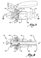
- the body of the female element A with a quick coupling shown in Figure 1 consists of the assembly of two tubular parts, namely a main part 1 and a part rear 2, this assembly being operated by elastic snap-fastening.
- An assembly formed by a tubular valve 3, a seat or seal 4, a valve holder 5 and a return spring 6 is held in place inside a central bore the of the part 1 thanks to part 2.
- the valve holder 5 ensures the retention an O-ring 7 intended to fulfill a sealing function.
- the valve 3 and the valve holder 5 can be produced in a single piece.
- the body formed of elements 1 and 2 is surrounded by an operating sleeve 8 and an anterior sleeve 9, the sleeve 9 being snapped elastically inside sleeve 8.
- a ring 10, called a locking ring, provided with longitudinal claws 10 has turned towards the front, that is to say to the left of FIG. 1, slides on the part 1.
- the free end of each of the claws 10 a has a profiled head 10 b intended to be trapped behind an external radial shoulder of a male end piece intended to cooperate with the female element A.
- the claws 10 a therefore constitute means for immobilizing a male part inside the female element A.
- the blower B is intended to be mounted in the element A. It comprises a body 51 in the form of a tubular sleeve provided with a radial peripheral groove 52 intended to receive the heads 10 b of the claws 10 a , to as shown in Figure 1. In this position, the body 51 is firmly immobilized relative to the female element A.
- a nozzle 54 in the form of a tube which can slide relative to the body 51.
- a lever 55 is articulated on the body 51 thanks to a pin 56 clipped into two legs of which only one is visible in the figures with the reference 57.
- a ring 63 having a radial face of diameter substantially equal to the exposed face of the valve holder 5.
- the end 62 of the nozzle 54 drives the ring 63 which pushes the valve holder 5 to against the force of the spring 6.
- This has the effect of remove the valve 3 from its seal 4 and allow circulation compressed air from the upstream pipe to the nozzle 54, which is represented by the flow arrow E.
- the air gun remains in this air flow position compressed as long as the handle 58 remains pressed on the sleeve 8.
- a notch 64 is provided on the outside of the nozzle 54 and defines two housings 65 and 66, for receiving the head 67 of an elastic tab 68 formed in the body 51.
- the head 67 is in place in the housing 65, so that the elasticity of the tab 68 is opposed to a movement of the nozzle 54 to the left of FIG. 2.
- the elasticity of the tab 68 makes it possible to create a reaction force to the valve closing force due to the spring 6. This construction improves user comfort blow gun if the user does not feel the entire thrust force due to the spring 6.
- the head 67 of lug 68 is in place in housing 66, so that it is opposed to an untimely operation of the lever 55.
- the insertion of the nozzle 54 towards the valve 3 can only result from user effort enough to move head 67 from tab 68 above notch 64. This avoids untimely opening of the blow gun.
- a stop 69 is provided on the body 51 to limit the movement of the leg 60, and therefore of the lever assembly 55, around the axis 56. In the position of FIGS. 2 and 3, the tab 60 is in support against the stop 69.
- the nozzle 54 carries a radial flange 70 intended to cooperate with a nose 71 of the lever 55 to limit the tilting movement of the lever 55 in the opposite direction at force F.
- the flange 70 serves as a stop for the nose 71 of the lever 55.
- the stops 69 and 70 make it possible to limit the amplitude of the pivoting of the lever 55 and, thereby, the displacement of the nozzle 54, this movement being moreover controlled elastically thanks to tab 68.
- Blow gun B can be easily assembled and disassembled on element A like the male end of a fitting fast while it works particularly satisfactory.
- blower B once disassembled of the female element A, constitutes a unitary assembly which can be stored without risk of disassembly.
- the invention has been presented with the articulated lever 55 around an axis.
- other means of controlling the sliding of the nozzle 54 in the body 51 can be used such as, in particular, an outer ring engaged with the nozzle.
- This ring could include a straight ramp or helical to increase the force applied to the nozzle.
Landscapes
- Nozzles (AREA)
- Catching Or Destruction (AREA)
- Structures Of Non-Positive Displacement Pumps (AREA)
- Quick-Acting Or Multi-Walled Pipe Joints (AREA)
- Reciprocating Pumps (AREA)
- Cleaning In General (AREA)
Applications Claiming Priority (2)
| Application Number | Priority Date | Filing Date | Title |
|---|---|---|---|
| FR9711033A FR2767896B1 (fr) | 1997-09-01 | 1997-09-01 | Soufflette a air comprime commandee par un levier |
| FR9711033 | 1997-09-01 |
Publications (2)
| Publication Number | Publication Date |
|---|---|
| EP0899028A1 true EP0899028A1 (de) | 1999-03-03 |
| EP0899028B1 EP0899028B1 (de) | 2002-10-16 |
Family
ID=9510778
Family Applications (1)
| Application Number | Title | Priority Date | Filing Date |
|---|---|---|---|
| EP98420148A Expired - Lifetime EP0899028B1 (de) | 1997-09-01 | 1998-08-28 | Hebelbetätigtes Druckluft-Blasmundstück |
Country Status (6)
| Country | Link |
|---|---|
| US (1) | US6032878A (de) |
| EP (1) | EP0899028B1 (de) |
| AT (1) | ATE226117T1 (de) |
| DE (1) | DE69808710T2 (de) |
| ES (1) | ES2182251T3 (de) |
| FR (1) | FR2767896B1 (de) |
Families Citing this family (2)
| Publication number | Priority date | Publication date | Assignee | Title |
|---|---|---|---|---|
| KR200239294Y1 (ko) * | 1999-05-20 | 2001-09-25 | 이황우 | 다기능용 에어건. |
| US6752335B2 (en) * | 2000-05-23 | 2004-06-22 | Summit Tool Company | Pivoting blow-gun |
Citations (2)
| Publication number | Priority date | Publication date | Assignee | Title |
|---|---|---|---|---|
| EP0223752A2 (de) * | 1985-11-19 | 1987-05-27 | Bono Gervasoni | Luftpistolengehäuse mit einem im Anschluss der Luftzufuhrleitung untergebrachten Ventil |
| US4676269A (en) * | 1986-03-07 | 1987-06-30 | Tuthill Corporation | Connector assembly |
Family Cites Families (1)
| Publication number | Priority date | Publication date | Assignee | Title |
|---|---|---|---|---|
| DE1425900A1 (de) * | 1965-05-07 | 1969-04-03 | Luciano Bracchino | Blas- oder Spritzgeraet |
-
1997
- 1997-09-01 FR FR9711033A patent/FR2767896B1/fr not_active Expired - Fee Related
-
1998
- 1998-08-03 US US09/127,831 patent/US6032878A/en not_active Expired - Lifetime
- 1998-08-28 AT AT98420148T patent/ATE226117T1/de not_active IP Right Cessation
- 1998-08-28 EP EP98420148A patent/EP0899028B1/de not_active Expired - Lifetime
- 1998-08-28 DE DE69808710T patent/DE69808710T2/de not_active Expired - Lifetime
- 1998-08-28 ES ES98420148T patent/ES2182251T3/es not_active Expired - Lifetime
Patent Citations (2)
| Publication number | Priority date | Publication date | Assignee | Title |
|---|---|---|---|---|
| EP0223752A2 (de) * | 1985-11-19 | 1987-05-27 | Bono Gervasoni | Luftpistolengehäuse mit einem im Anschluss der Luftzufuhrleitung untergebrachten Ventil |
| US4676269A (en) * | 1986-03-07 | 1987-06-30 | Tuthill Corporation | Connector assembly |
Also Published As
| Publication number | Publication date |
|---|---|
| FR2767896A1 (fr) | 1999-03-05 |
| FR2767896B1 (fr) | 1999-10-22 |
| ATE226117T1 (de) | 2002-11-15 |
| EP0899028B1 (de) | 2002-10-16 |
| US6032878A (en) | 2000-03-07 |
| ES2182251T3 (es) | 2003-03-01 |
| DE69808710D1 (de) | 2002-11-21 |
| DE69808710T2 (de) | 2003-07-03 |
Similar Documents
| Publication | Publication Date | Title |
|---|---|---|
| CA2754552C (fr) | Dispositif de raccord avec verrouillage par griffes filetees et raccord comprenant un tel dispositif | |
| EP1557599B1 (de) | Schnellkupplung und Verfahren zum Lösen der ineinander gesteckten Teile der Schnellkupplung | |
| EP1308663B1 (de) | Schnellkupplung für die lösbare Verbindung zweier Rohrleitungen | |
| EP1526318B1 (de) | Schnellkupplung für die lösbare Verbindung zweier Leitungen und Verwendung einer solchen Kupplung | |
| EP1934511B1 (de) | Sicherheits-schnellanschluss-kupplung für das zusammenbauen von zwei rohren | |
| EP2306061B1 (de) | Schnellkupplungsmuffe und Schnellkupplung mit solcher Schnellkupplungsmuffe | |
| EP2278205B1 (de) | Kupplungsaufnahme und diese beinhaltende Schnellkupplung | |
| EP3827902B1 (de) | Kit für sprühpistole, anwendungsverfahren und entsprechende pistole | |
| EP2926912B1 (de) | Luftdüse für druckluft | |
| EP0722063A2 (de) | Sicherheitsschnellkupplung für lösbare Verbindung von Rohrleitungen | |
| CH629661A5 (fr) | Piece a main dentaire munie d'un dispositif de reglage des liquides d'arrosage de l'outil. | |
| EP1106212B1 (de) | Feuerlöschdüse | |
| FR2939863A1 (fr) | Dispositif de raccordement epuipe de moyens instantane ou quasi-instantane | |
| EP0623429A1 (de) | Pneumatisches Werkzeug | |
| FR2715454A1 (fr) | Connexion rapide. | |
| EP1521027A1 (de) | Demontiereinrichtung für Schnellkupplung | |
| FR2837487A1 (fr) | Pistolet a fonctionnement securise et installation de remplissage comprenant un tel pistolet | |
| EP0899028B1 (de) | Hebelbetätigtes Druckluft-Blasmundstück | |
| FR2786423A1 (fr) | Outil emporte-piece hydraulique | |
| EP4336080B1 (de) | Schnellkupplungsbuchse | |
| FR2875571A1 (fr) | Soupape d'admission pour outil pneumatique | |
| EP2567789B1 (de) | Montagegerät eines Befestigungselements | |
| FR2634536A1 (fr) | Raccord rapide de pompe a une valve de pneumatique avec un embout a bague saillante | |
| FR2726346A1 (fr) | Dispositif de raccordement fluidique | |
| FR2911053A3 (fr) | Dispositif de securite pour contenant cosmetique du type a poussoir |
Legal Events
| Date | Code | Title | Description |
|---|---|---|---|
| PUAI | Public reference made under article 153(3) epc to a published international application that has entered the european phase |
Free format text: ORIGINAL CODE: 0009012 |
|
| AK | Designated contracting states |
Kind code of ref document: A1 Designated state(s): AT BE CH DE DK ES FR GB IE IT LI NL SE |
|
| AX | Request for extension of the european patent |
Free format text: AL;LT;LV;MK;RO;SI |
|
| 17P | Request for examination filed |
Effective date: 19990421 |
|
| AKX | Designation fees paid |
Free format text: AT BE CH DE DK ES FR GB IE IT LI NL SE |
|
| GRAG | Despatch of communication of intention to grant |
Free format text: ORIGINAL CODE: EPIDOS AGRA |
|
| 17Q | First examination report despatched |
Effective date: 20020418 |
|
| GRAG | Despatch of communication of intention to grant |
Free format text: ORIGINAL CODE: EPIDOS AGRA |
|
| GRAH | Despatch of communication of intention to grant a patent |
Free format text: ORIGINAL CODE: EPIDOS IGRA |
|
| GRAH | Despatch of communication of intention to grant a patent |
Free format text: ORIGINAL CODE: EPIDOS IGRA |
|
| GRAA | (expected) grant |
Free format text: ORIGINAL CODE: 0009210 |
|
| AK | Designated contracting states |
Kind code of ref document: B1 Designated state(s): AT BE CH DE DK ES FR GB IE IT LI NL SE |
|
| PG25 | Lapsed in a contracting state [announced via postgrant information from national office to epo] |
Ref country code: NL Free format text: LAPSE BECAUSE OF FAILURE TO SUBMIT A TRANSLATION OF THE DESCRIPTION OR TO PAY THE FEE WITHIN THE PRESCRIBED TIME-LIMIT Effective date: 20021016 Ref country code: IE Free format text: LAPSE BECAUSE OF FAILURE TO SUBMIT A TRANSLATION OF THE DESCRIPTION OR TO PAY THE FEE WITHIN THE PRESCRIBED TIME-LIMIT Effective date: 20021016 Ref country code: AT Free format text: LAPSE BECAUSE OF FAILURE TO SUBMIT A TRANSLATION OF THE DESCRIPTION OR TO PAY THE FEE WITHIN THE PRESCRIBED TIME-LIMIT Effective date: 20021016 |
|
| REF | Corresponds to: |
Ref document number: 226117 Country of ref document: AT Date of ref document: 20021115 Kind code of ref document: T |
|
| REG | Reference to a national code |
Ref country code: GB Ref legal event code: FG4D Free format text: NOT ENGLISH |
|
| RIN1 | Information on inventor provided before grant (corrected) |
Inventor name: LAPORTE, CHRISTOPHE Inventor name: LACROIX, JEAN JACQUES |
|
| REG | Reference to a national code |
Ref country code: CH Ref legal event code: EP |
|
| REG | Reference to a national code |
Ref country code: IE Ref legal event code: FG4D Free format text: FRENCH |
|
| REF | Corresponds to: |
Ref document number: 69808710 Country of ref document: DE Date of ref document: 20021121 |
|
| PG25 | Lapsed in a contracting state [announced via postgrant information from national office to epo] |
Ref country code: SE Free format text: LAPSE BECAUSE OF FAILURE TO SUBMIT A TRANSLATION OF THE DESCRIPTION OR TO PAY THE FEE WITHIN THE PRESCRIBED TIME-LIMIT Effective date: 20030116 Ref country code: DK Free format text: LAPSE BECAUSE OF FAILURE TO SUBMIT A TRANSLATION OF THE DESCRIPTION OR TO PAY THE FEE WITHIN THE PRESCRIBED TIME-LIMIT Effective date: 20030116 |
|
| GBT | Gb: translation of ep patent filed (gb section 77(6)(a)/1977) |
Effective date: 20030122 |
|
| REG | Reference to a national code |
Ref country code: ES Ref legal event code: FG2A Ref document number: 2182251 Country of ref document: ES Kind code of ref document: T3 |
|
| NLV1 | Nl: lapsed or annulled due to failure to fulfill the requirements of art. 29p and 29m of the patents act | ||
| REG | Reference to a national code |
Ref country code: IE Ref legal event code: FD4D Ref document number: 0899028E Country of ref document: IE |
|
| PLBE | No opposition filed within time limit |
Free format text: ORIGINAL CODE: 0009261 |
|
| STAA | Information on the status of an ep patent application or granted ep patent |
Free format text: STATUS: NO OPPOSITION FILED WITHIN TIME LIMIT |
|
| 26N | No opposition filed |
Effective date: 20030717 |
|
| REG | Reference to a national code |
Ref country code: FR Ref legal event code: PLFP Year of fee payment: 19 |
|
| PGFP | Annual fee paid to national office [announced via postgrant information from national office to epo] |
Ref country code: CH Payment date: 20160829 Year of fee payment: 19 Ref country code: IT Payment date: 20160824 Year of fee payment: 19 Ref country code: DE Payment date: 20160826 Year of fee payment: 19 Ref country code: GB Payment date: 20160830 Year of fee payment: 19 |
|
| PGFP | Annual fee paid to national office [announced via postgrant information from national office to epo] |
Ref country code: FR Payment date: 20160825 Year of fee payment: 19 |
|
| PGFP | Annual fee paid to national office [announced via postgrant information from national office to epo] |
Ref country code: ES Payment date: 20160826 Year of fee payment: 19 Ref country code: BE Payment date: 20160829 Year of fee payment: 19 |
|
| REG | Reference to a national code |
Ref country code: DE Ref legal event code: R119 Ref document number: 69808710 Country of ref document: DE |
|
| REG | Reference to a national code |
Ref country code: CH Ref legal event code: PL |
|
| GBPC | Gb: european patent ceased through non-payment of renewal fee |
Effective date: 20170828 |
|
| PG25 | Lapsed in a contracting state [announced via postgrant information from national office to epo] |
Ref country code: LI Free format text: LAPSE BECAUSE OF NON-PAYMENT OF DUE FEES Effective date: 20170831 Ref country code: CH Free format text: LAPSE BECAUSE OF NON-PAYMENT OF DUE FEES Effective date: 20170831 |
|
| REG | Reference to a national code |
Ref country code: FR Ref legal event code: ST Effective date: 20180430 |
|
| REG | Reference to a national code |
Ref country code: BE Ref legal event code: MM Effective date: 20170831 |
|
| PG25 | Lapsed in a contracting state [announced via postgrant information from national office to epo] |
Ref country code: GB Free format text: LAPSE BECAUSE OF NON-PAYMENT OF DUE FEES Effective date: 20170828 Ref country code: DE Free format text: LAPSE BECAUSE OF NON-PAYMENT OF DUE FEES Effective date: 20180301 |
|
| PG25 | Lapsed in a contracting state [announced via postgrant information from national office to epo] |
Ref country code: BE Free format text: LAPSE BECAUSE OF NON-PAYMENT OF DUE FEES Effective date: 20170831 Ref country code: FR Free format text: LAPSE BECAUSE OF NON-PAYMENT OF DUE FEES Effective date: 20170831 Ref country code: IT Free format text: LAPSE BECAUSE OF NON-PAYMENT OF DUE FEES Effective date: 20170828 |
|
| REG | Reference to a national code |
Ref country code: ES Ref legal event code: FD2A Effective date: 20181024 |
|
| PG25 | Lapsed in a contracting state [announced via postgrant information from national office to epo] |
Ref country code: ES Free format text: LAPSE BECAUSE OF NON-PAYMENT OF DUE FEES Effective date: 20170829 |