EP4336080B1 - Schnellkupplungsbuchse - Google Patents
Schnellkupplungsbuchse Download PDFInfo
- Publication number
- EP4336080B1 EP4336080B1 EP23195922.2A EP23195922A EP4336080B1 EP 4336080 B1 EP4336080 B1 EP 4336080B1 EP 23195922 A EP23195922 A EP 23195922A EP 4336080 B1 EP4336080 B1 EP 4336080B1
- Authority
- EP
- European Patent Office
- Prior art keywords
- female element
- lock
- longitudinal axis
- operating ring
- axis
- Prior art date
- Legal status (The legal status is an assumption and is not a legal conclusion. Google has not performed a legal analysis and makes no representation as to the accuracy of the status listed.)
- Active
Links
Images


Classifications
-
- F—MECHANICAL ENGINEERING; LIGHTING; HEATING; WEAPONS; BLASTING
- F16—ENGINEERING ELEMENTS AND UNITS; GENERAL MEASURES FOR PRODUCING AND MAINTAINING EFFECTIVE FUNCTIONING OF MACHINES OR INSTALLATIONS; THERMAL INSULATION IN GENERAL
- F16L—PIPES; JOINTS OR FITTINGS FOR PIPES; SUPPORTS FOR PIPES, CABLES OR PROTECTIVE TUBING; MEANS FOR THERMAL INSULATION IN GENERAL
- F16L37/00—Couplings of the quick-acting type
- F16L37/28—Couplings of the quick-acting type with fluid cut-off means
- F16L37/38—Couplings of the quick-acting type with fluid cut-off means with fluid cut-off means in only one of two pipe-end fittings
- F16L37/40—Couplings of the quick-acting type with fluid cut-off means with fluid cut-off means in only one of two pipe-end fittings with a lift valve being opened automatically when the coupling is applied
- F16L37/413—Couplings of the quick-acting type with fluid cut-off means with fluid cut-off means in only one of two pipe-end fittings with a lift valve being opened automatically when the coupling is applied the lift valve being of the sleeve type, i.e. a sleeve being telescoped over an inner cylindrical wall
-
- F—MECHANICAL ENGINEERING; LIGHTING; HEATING; WEAPONS; BLASTING
- F16—ENGINEERING ELEMENTS AND UNITS; GENERAL MEASURES FOR PRODUCING AND MAINTAINING EFFECTIVE FUNCTIONING OF MACHINES OR INSTALLATIONS; THERMAL INSULATION IN GENERAL
- F16L—PIPES; JOINTS OR FITTINGS FOR PIPES; SUPPORTS FOR PIPES, CABLES OR PROTECTIVE TUBING; MEANS FOR THERMAL INSULATION IN GENERAL
- F16L33/00—Arrangements for connecting hoses to rigid members; Rigid hose-connectors, i.e. single members engaging both hoses
- F16L33/22—Arrangements for connecting hoses to rigid members; Rigid hose-connectors, i.e. single members engaging both hoses with means not mentioned in the preceding groups for gripping the hose between inner and outer parts
- F16L33/227—Arrangements for connecting hoses to rigid members; Rigid hose-connectors, i.e. single members engaging both hoses with means not mentioned in the preceding groups for gripping the hose between inner and outer parts the hose being introduced into or onto the connecting member and automatically locked
-
- F—MECHANICAL ENGINEERING; LIGHTING; HEATING; WEAPONS; BLASTING
- F16—ENGINEERING ELEMENTS AND UNITS; GENERAL MEASURES FOR PRODUCING AND MAINTAINING EFFECTIVE FUNCTIONING OF MACHINES OR INSTALLATIONS; THERMAL INSULATION IN GENERAL
- F16L—PIPES; JOINTS OR FITTINGS FOR PIPES; SUPPORTS FOR PIPES, CABLES OR PROTECTIVE TUBING; MEANS FOR THERMAL INSULATION IN GENERAL
- F16L37/00—Couplings of the quick-acting type
- F16L37/28—Couplings of the quick-acting type with fluid cut-off means
- F16L37/38—Couplings of the quick-acting type with fluid cut-off means with fluid cut-off means in only one of two pipe-end fittings
- F16L37/46—Couplings of the quick-acting type with fluid cut-off means with fluid cut-off means in only one of two pipe-end fittings with a gate valve or sliding valve
-
- F—MECHANICAL ENGINEERING; LIGHTING; HEATING; WEAPONS; BLASTING
- F16—ENGINEERING ELEMENTS AND UNITS; GENERAL MEASURES FOR PRODUCING AND MAINTAINING EFFECTIVE FUNCTIONING OF MACHINES OR INSTALLATIONS; THERMAL INSULATION IN GENERAL
- F16L—PIPES; JOINTS OR FITTINGS FOR PIPES; SUPPORTS FOR PIPES, CABLES OR PROTECTIVE TUBING; MEANS FOR THERMAL INSULATION IN GENERAL
- F16L33/00—Arrangements for connecting hoses to rigid members; Rigid hose-connectors, i.e. single members engaging both hoses
- F16L33/22—Arrangements for connecting hoses to rigid members; Rigid hose-connectors, i.e. single members engaging both hoses with means not mentioned in the preceding groups for gripping the hose between inner and outer parts
- F16L33/225—Arrangements for connecting hoses to rigid members; Rigid hose-connectors, i.e. single members engaging both hoses with means not mentioned in the preceding groups for gripping the hose between inner and outer parts a sleeve being movable axially
-
- F—MECHANICAL ENGINEERING; LIGHTING; HEATING; WEAPONS; BLASTING
- F16—ENGINEERING ELEMENTS AND UNITS; GENERAL MEASURES FOR PRODUCING AND MAINTAINING EFFECTIVE FUNCTIONING OF MACHINES OR INSTALLATIONS; THERMAL INSULATION IN GENERAL
- F16L—PIPES; JOINTS OR FITTINGS FOR PIPES; SUPPORTS FOR PIPES, CABLES OR PROTECTIVE TUBING; MEANS FOR THERMAL INSULATION IN GENERAL
- F16L37/00—Couplings of the quick-acting type
- F16L37/08—Couplings of the quick-acting type in which the connection between abutting or axially overlapping ends is maintained by locking members
- F16L37/084—Couplings of the quick-acting type in which the connection between abutting or axially overlapping ends is maintained by locking members combined with automatic locking
- F16L37/0841—Couplings of the quick-acting type in which the connection between abutting or axially overlapping ends is maintained by locking members combined with automatic locking by means of a transversally slidable locking member surrounding the tube
-
- F—MECHANICAL ENGINEERING; LIGHTING; HEATING; WEAPONS; BLASTING
- F16—ENGINEERING ELEMENTS AND UNITS; GENERAL MEASURES FOR PRODUCING AND MAINTAINING EFFECTIVE FUNCTIONING OF MACHINES OR INSTALLATIONS; THERMAL INSULATION IN GENERAL
- F16L—PIPES; JOINTS OR FITTINGS FOR PIPES; SUPPORTS FOR PIPES, CABLES OR PROTECTIVE TUBING; MEANS FOR THERMAL INSULATION IN GENERAL
- F16L37/00—Couplings of the quick-acting type
- F16L37/08—Couplings of the quick-acting type in which the connection between abutting or axially overlapping ends is maintained by locking members
- F16L37/084—Couplings of the quick-acting type in which the connection between abutting or axially overlapping ends is maintained by locking members combined with automatic locking
- F16L37/086—Couplings of the quick-acting type in which the connection between abutting or axially overlapping ends is maintained by locking members combined with automatic locking by means of latching members pushed radially by spring-like elements
-
- F—MECHANICAL ENGINEERING; LIGHTING; HEATING; WEAPONS; BLASTING
- F16—ENGINEERING ELEMENTS AND UNITS; GENERAL MEASURES FOR PRODUCING AND MAINTAINING EFFECTIVE FUNCTIONING OF MACHINES OR INSTALLATIONS; THERMAL INSULATION IN GENERAL
- F16L—PIPES; JOINTS OR FITTINGS FOR PIPES; SUPPORTS FOR PIPES, CABLES OR PROTECTIVE TUBING; MEANS FOR THERMAL INSULATION IN GENERAL
- F16L37/00—Couplings of the quick-acting type
- F16L37/08—Couplings of the quick-acting type in which the connection between abutting or axially overlapping ends is maintained by locking members
- F16L37/12—Couplings of the quick-acting type in which the connection between abutting or axially overlapping ends is maintained by locking members using hooks, pawls, or other movable or insertable locking members
- F16L37/122—Couplings of the quick-acting type in which the connection between abutting or axially overlapping ends is maintained by locking members using hooks, pawls, or other movable or insertable locking members using hooks tightened by a wedge section
-
- F—MECHANICAL ENGINEERING; LIGHTING; HEATING; WEAPONS; BLASTING
- F16—ENGINEERING ELEMENTS AND UNITS; GENERAL MEASURES FOR PRODUCING AND MAINTAINING EFFECTIVE FUNCTIONING OF MACHINES OR INSTALLATIONS; THERMAL INSULATION IN GENERAL
- F16L—PIPES; JOINTS OR FITTINGS FOR PIPES; SUPPORTS FOR PIPES, CABLES OR PROTECTIVE TUBING; MEANS FOR THERMAL INSULATION IN GENERAL
- F16L37/00—Couplings of the quick-acting type
- F16L37/08—Couplings of the quick-acting type in which the connection between abutting or axially overlapping ends is maintained by locking members
- F16L37/12—Couplings of the quick-acting type in which the connection between abutting or axially overlapping ends is maintained by locking members using hooks, pawls, or other movable or insertable locking members
- F16L37/138—Couplings of the quick-acting type in which the connection between abutting or axially overlapping ends is maintained by locking members using hooks, pawls, or other movable or insertable locking members using an axially movable sleeve
-
- F—MECHANICAL ENGINEERING; LIGHTING; HEATING; WEAPONS; BLASTING
- F16—ENGINEERING ELEMENTS AND UNITS; GENERAL MEASURES FOR PRODUCING AND MAINTAINING EFFECTIVE FUNCTIONING OF MACHINES OR INSTALLATIONS; THERMAL INSULATION IN GENERAL
- F16L—PIPES; JOINTS OR FITTINGS FOR PIPES; SUPPORTS FOR PIPES, CABLES OR PROTECTIVE TUBING; MEANS FOR THERMAL INSULATION IN GENERAL
- F16L37/00—Couplings of the quick-acting type
- F16L37/22—Couplings of the quick-acting type in which the connection is maintained by means of balls, rollers or helical springs under radial pressure between the parts
-
- F—MECHANICAL ENGINEERING; LIGHTING; HEATING; WEAPONS; BLASTING
- F16—ENGINEERING ELEMENTS AND UNITS; GENERAL MEASURES FOR PRODUCING AND MAINTAINING EFFECTIVE FUNCTIONING OF MACHINES OR INSTALLATIONS; THERMAL INSULATION IN GENERAL
- F16L—PIPES; JOINTS OR FITTINGS FOR PIPES; SUPPORTS FOR PIPES, CABLES OR PROTECTIVE TUBING; MEANS FOR THERMAL INSULATION IN GENERAL
- F16L37/00—Couplings of the quick-acting type
- F16L37/28—Couplings of the quick-acting type with fluid cut-off means
- F16L37/38—Couplings of the quick-acting type with fluid cut-off means with fluid cut-off means in only one of two pipe-end fittings
- F16L37/40—Couplings of the quick-acting type with fluid cut-off means with fluid cut-off means in only one of two pipe-end fittings with a lift valve being opened automatically when the coupling is applied
- F16L37/42—Couplings of the quick-acting type with fluid cut-off means with fluid cut-off means in only one of two pipe-end fittings with a lift valve being opened automatically when the coupling is applied the valve having an axial bore communicating with lateral apertures
-
- F—MECHANICAL ENGINEERING; LIGHTING; HEATING; WEAPONS; BLASTING
- F16—ENGINEERING ELEMENTS AND UNITS; GENERAL MEASURES FOR PRODUCING AND MAINTAINING EFFECTIVE FUNCTIONING OF MACHINES OR INSTALLATIONS; THERMAL INSULATION IN GENERAL
- F16L—PIPES; JOINTS OR FITTINGS FOR PIPES; SUPPORTS FOR PIPES, CABLES OR PROTECTIVE TUBING; MEANS FOR THERMAL INSULATION IN GENERAL
- F16L2201/00—Special arrangements for pipe couplings
- F16L2201/10—Indicators for correct coupling
Definitions
- the present invention relates to a female quick coupling element.
- Quick couplings are fluid connection devices comprising a female element and a mating male element.
- Each of the male and female elements includes an internal passage, the internal passages being in fluid communication when the coupling is in the connected configuration.
- the female element most often includes a locking device, which engages when the male and female elements are connected, so as to hold the coupling in the connected configuration, hence the name quick coupling.
- the male element is a hose, that is to say a flexible pipe, in which a fluid circulates under high pressure.
- hose that is to say a flexible pipe
- Such quick locking devices present a danger of untimely uncoupling under pressure, which could be a source of breakdown or incident for the installation.
- hose is connected to the female element and then disconnected repeatedly.
- hoses are typically made of polymer material and have slightly varying thicknesses.
- a hose connector comprising a hollow connecting cannula secured to a body of a female connecting element, and an outer ring held elastically on the front of the female element.
- This ring comprises an inner collar, which clamps the hose directly on the cannula.
- the outer ring is held on the front by a spring which presses the hose against the cannula, via the inner collar.
- the operator must act by axial traction on the ring to unlock the connector.
- the cooperation of the collar and the cannula has the disadvantage of marking the hose and stressing it axially by friction, in addition to representing too great a tensile force for the user.
- the direct application of a reduced force of the spring, through the ring does not represent a reliable means of retaining the hose when the pressure is established.
- US-3 188 123-A describes, for its part, a connection comprising locking pins 33, which are pushed into a retaining position by a sleeve 43.
- the invention aims to address more specifically by proposing a female quick coupling element which allows secure coupling, including on pipes with slightly varying thicknesses.
- the movements of the locks are controlled by the operating ring, come to bear against the pipe and exert a bearing force orthogonal to the longitudinal axis, reducing the risks of marking the pipe. In the event of repeated connections and disconnections, the risks of leaks and/or rupture of the pipe are reduced.
- the movement of the locks makes it possible to compensate for dimensional clearances, in particular variations in the thickness of the pipes.
- the bearing force which is exerted by the return member and transmitted by the locks, depends little on variations in the thickness of the pipes, the coupling is thus secure.
- the use of inclined guide grooves makes it possible, by multiplying the forces, to apply a significant locking force to the pipe without degrading the ease of disconnection of the coupling by the operation of the locking ring.
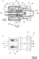
- FIG. 1 represents a fitting R, which comprises a male element, here a pipe 10, on the left of the Figure 1 , and an associated female element 100, on the right of the Figure 1 .
- the connector R is here shown in an uncoupled configuration, in which the pipe 10 and the female element 100 are separated from each other.
- the pipe 10 is a flexible pipe, also called a “hose”. Only an end portion of the pipe 10 is shown in the figures, this end portion being considered rectilinear.
- the pipe 10 is here centered on a pipe axis A10.
- the pipe 10 comprises an inner surface 12A, of cylindrical shape with circular section and characterized by an inner diameter d10, an outer surface 12B, also of cylindrical shape with circular section and characterized by an outer diameter D10.
- the pipe 10 also has a front face 14, which connects the inner surface 12A and the outer surface 12B and which is oriented towards the female element 100 when the female element 100 is connected to the pipe 10.
- the pipe 10 has a thickness E10 measured radially to the axis A10, between the outer surface 12B and the inner surface 12A.
- the pipe 10 is made of an elastically deformable polymer material.
- the pipe 10 is for example manufactured by extrusion. Due to manufacturing variations and/or deformations of the pipe 10 during its use, the dimensions of the pipe 10, namely the inner diameter d10, the outer diameter D10 and the thickness E10, exhibit variations, for example of ⁇ 10%.
- the female element 100 comprises a body 102, which has a generally revolution shape around a longitudinal axis A100.
- the longitudinal axis A100 is aligned with the pipe axis A10 and these aligned axes together define a fitting axis of the connector R.
- the body 102 is here made in two parts and comprises a proximal part 104, in which is provided a threaded hole 105 intended to fix a fluid pipe there, and a distal part 106, which is here assembled to the proximal part 104 by screwing.
- the fluid pipe is not shown.
- the threaded hole 105 defines a rear side of the body 102 and, by extension, a rear side of the female element 100.
- a front side is a side opposite the rear side.
- the body 102 of the female element 100 is hollow and delimits a fluid passage V100.
- the fluid passage V100 opens here, on the rear side, through the threaded hole 105.
- an axis radial to this first axis is an axis orthogonal to this first axis.
- a plane transverse to this first axis is a plane orthogonal to this first axis.
- An axis orthoradial to this first axis is an axis which is carried by a plane transverse to this first axis and which is not intersecting this first axis.
- the female element 100 also comprises a cannula 120.
- the cannula 120 is secured to the body 102.
- the cannula 120 is assembled by screwing to the proximal part 104.
- the cannula 120 comprises a base 122, by means of which the cannula 120 is assembled to the proximal part 104, and a front portion 124, which has an elongated shape and which extends parallel to the longitudinal axis A100 and which is configured to be fitted into the pipe 10.
- the base 122 provides a stop surface 125, which is oriented forward and from which the front portion 124 extends.
- the stop surface 125 is located in a plane transverse to the longitudinal axis A100.
- the stop surface 125 limits the amplitude of movement of the pipe 10 towards the rear of the female element 100, parallel to the longitudinal axis A100.
- the distal portion 106 here provides a mounting volume V106, which houses a subassembly comprising the cannula 120 and the proximal portion 104.
- the distal portion 106 comprises a shoulder 108, which is provided in the mounting volume V106 and which is oriented towards the rear, the abutment surface 125 bearing against the shoulder 108.
- the shoulder 108 is therefore aligned, along the longitudinal axis A100, with the abutment surface 125.
- the distal portion 106 comprises a projection 110, which has a shape of revolution around the longitudinal axis A100, which extends forwards at a distance from the cannula 120 and which provides a receiving volume V110 for the pipe 10.
- the receiving volume V110 is configured to receive the pipe 10 when the pipe 10 is fitted onto the cannula 120.
- the receiving volume V110 has a shape of revolution around the longitudinal axis A100, is delimited on the rear side by the abutment surface 125 and opens out of the body 102, towards the front, by a mouth 126.
- the mouth 126 is preferably circular and has a diameter greater than the external diameter D10 of the pipe 10.
- the cannula 120 has a shape of revolution around the longitudinal axis A100 and provides a channel V120.
- the channel V120 is therefore centered on the longitudinal axis A100.
- the cannula 120 is fluidically connected to the proximal portion 104.
- the channel V120 opens, on the one hand, on the front side of the female element 100 and, on the other hand, into the passage V100.
- the cannula 120 includes an outer surface that extends into the receiving volume V110.
- the outer surface of the cannula 120 is configured to engage the pipe 10.
- the inner surface 12A of the pipe 10 is received on the outer cannula surface when the pipe 10 is engaged on the cannula 120.
- the outer cannula surface is configured to receive the inner surface 12A of the pipe in that the end of the portion front 124 of the cannula 120 has a diameter close to or less than the internal diameter d10 of the pipe 10.
- a circumferential bulge 128 is advantageously provided projecting from the front portion 124 of the cannula 120.
- the circumferential bulge 128 is configured to cooperate with the internal surface 12A of the pipe 10, so as to improve the seal between the pipe 10 and the cannula 120 and to retain the internal surface 12A of the pipe fitted onto the cannula 120.
- the circumferential bulge 128 is arranged at a front end of the front portion 124 of the cannula 120.
- the circumferential bulge 128 comprises, successively starting from the mouth of the cannula 120 and moving rearwardly, a distal portion 129A, which is divergent towards the rear of the female element 100 and which is configured to facilitate fitting of the cannula 120 in the pipe 10, and a proximal portion 129B, which is divergent towards the front of the female element 100.
- a first clamping plane P129 which is a plane transverse to the longitudinal axis A100.
- the pipe 10 When the pipe 10 is fitted onto the cannula 120, the pipe 10 deforms elastically and accommodates the passage of the circumferential bulge 128. It is considered that the internal surface 12A of the pipe 10 matches the external surface of the cannula 10, in particular matches the profile of the bulge 128 by elastic deformation so as to produce a sealing section between the pipe 10 and the cannula 120.
- the body 102 also comprises at least one radial opening 130.
- the body 102 comprises two radial openings 130, which are arranged through the projection 110.
- Each radial opening 130 is arranged in the body 102 along a respective guide axis A130.
- Each guide axis A130 is radial to the longitudinal axis A100.
- Each radial opening 130 opens into the receiving volume V110.
- the two radial openings 130 are here diametrically opposite each other with respect to the longitudinal axis A100, which means that the two guide axes A130 are aligned.
- the guide axes A130 are located in a longitudinal plane P100 of the female element 100, the longitudinal plane P100 being the section plane of the Figure 1 .
- each radial opening 130 has, in a plane orthogonal to the corresponding guide axis A130, a generally rectangular section.
- Each radial opening 130 thus comprises two transverse walls 132A, which extend opposite each other orthogonally to the longitudinal axis A100, and two lateral walls 132B, which extend opposite each other parallel to the longitudinal axis A100.
- the transverse walls 132A and the lateral walls 132B are parallel to the corresponding guide axis A130.
- each radial opening 130 has walls 132A and 132B which are parallel to the corresponding guide axis A130.
- clearances 134 are provided perpendicular to the two side walls 132B.
- the clearances 134 are here produced by milling and each have a semi-cylindrical shape, the clearances 134 being centered on an axis orthoradial to the longitudinal axis A100.
- fillets 136 are provided at each of the junctions between the side walls 132B and the clearances 134.
- the fillets 136 are here rounded machinings, provided by drillings parallel to the corresponding guide axis A130.
- Each radial opening 130 receives a lock 140, each lock 140 being movable in translation relative to the body 102 of the female element 100 in a direction parallel to the guide axis A130 of the radial opening 130 in which this lock 140 is received.
- the body 102 comprises a first viewing light 138, which extends through the body 102 along a viewing axis A138 radial to the longitudinal axis A100.
- the first light 138 here has a cylindrical shape of substantially rectangular section, the first light 138 being arranged in its length transversely to the longitudinal axis A100.
- the first light 138 is provided in front of the abutment surface 125.
- the first light 138 opens into the receiving volume V110.
- the first light 138 opens outside the body 102.
- the first light 138 is arranged so as to allow observation, through the first light 138, of a portion of the abutment surface 125.
- the body 102 comprises two first lights 138, which are arranged between each of the radial openings 130 and the stop surface 125, the sight axes A138 being parallel to the guide axes A130.
- a 140 lock is shown isolated on the Figure 2 .
- the locks 140 are now described with particular reference to the Figure 2 .
- the two locks 140 of the female element 102 are preferably identical to each other.
- Each lock 140 has a peripheral surface 142 centered on a lock axis A140.
- the lock axis A140 of this lock coincides with the radial axis A130 of the corresponding radial opening 130.
- the peripheral surface 142 is configured to cooperate with the transverse 132A and lateral 132B walls of the radial opening 130, in particular by complementarity of shapes, so as to guide the lock 140, received in the corresponding radial opening 130, in translation along the merged axes A130 and A140.
- the peripheral surface 142 has, in section in a plane orthogonal to the lock axis A140, a rectangular profile.
- the peripheral surface 142 comprises a distal face 144, which is oriented towards the mouth 126 when the lock 140 is received in the corresponding radial opening 130, a proximal face 146, which is oriented opposite the distal face 144 and therefore oriented on the opposite side of the mouth 126, the distal face 144 and the proximal face 146 being connected to each other by two lateral faces 148.
- the distal 144, proximal 146 and lateral 148 faces are preferably planar.
- the distal face 144 is geometrically supported by a second clamping plane P144, which is a plane transverse to the longitudinal axis A100 when the female element 100 is assembled.
- Each lock 140 also comprises an internal surface 150, which is here a generally concave surface crossed by the corresponding lock axis A140.
- the internal surface 150 is oriented towards the longitudinal axis A100 opposite the external surface of the cannula 120 when the lock 140 is received in the associated radial opening 130.
- Each lock 140 also comprises an external face 151, which is oriented opposite the internal face 150 along the lock axis A140.
- each internal surface 150 is configured to bear on the external surface 12B of the pipe 10 when the pipe 10 is fitted onto the cannula 120, so as to clamp the pipe 10 and prevent it from sliding on the cannula 120.
- Each internal surface 150 is therefore a clamping surface of the corresponding lock 140.
- a median plane P140 of the lock 140 is defined as being a plane parallel to the distal face 144 and containing the lock axis A140.
- the median plane P140 is here a plane of symmetry of the lock 140.
- each internal surface 150 is a portion of a cylinder of circular section and centered on an axis A150 orthogonal to the median plane P140.
- the internal surface 150 has a diameter substantially equal to the diameter of the mouth 126.
- the internal surface 150 has, in projection onto the median plane P140, a profile in the form of an arc of a circle centered on the axis A150.
- a clamping angle ⁇ 150 is defined as being the angle of this arc of a circle measured around the axis A150 on which this arc of a circle is centered.
- the clamping angle ⁇ 150 is as large as possible, so as to increase a contact surface between each lock 140 and the pipe 10.
- the clamping angle ⁇ 150 is greater than or equal to 90°, preferably greater than or equal to 120°, more preferably greater than or equal to 160°. In the example illustrated, the clamping angle ⁇ 150 is equal to 160°.
- the locks 140 are shown in section.
- the internal face 150 is connected to the corresponding distal 144 and proximal 146 faces by two respective rounded edges 153, so as to reduce the risks of marking the pipe 10 when the latter is held by the locks 140, as explained later.
- a through bore 152 is provided through each lock 140, the bore 152 opening onto each of the lateral faces 148 of the lock.
- the bore 152 is centered on an axis A152, which is parallel to the median plane P140 and orthogonal to the lock axis A140.
- the axis A152 of the bore 152 is orthoradial to the longitudinal axis A100.
- Each lock 140 comprises a rod 154, which is received in the corresponding bore 152 and which protrudes from each of the lateral faces 148, so as to form two guide pins 156.
- the rod 154 is here held in the bore 152 by means of a pressure screw 158 inserted in a thread 159 which opens onto the external face 151.
- the pins 156 of each lock 150 thus extend in the direction of the axis A152 of the bore 152, in other words in a direction orthogonal to the radial axis A130 of the corresponding radial opening 130.
- a width l140 of each lock 140 is defined as being a distance between the two lateral faces 148 of this lock 140.
- the width l140 is substantially equal, apart from assembly clearances, to a distance between the two lateral surfaces 132B of a radial opening 130.
- the width l140 is greater than 50% of the diameter of the mouth 126 - in other words greater than a radius of the mouth 126 -, preferably greater than 75% of the diameter of the mouth 126, more preferably still greater than the diameter of the mouth 126. This ensures a contact surface between each lock 140 and the pipe 10 that is as large as possible.
- each lock 140 advantageously comprises rollers 160, which are each assembled to a respective pin 156.
- the rollers 160 are advantageously mounted to be movable in rotation relative to the rod 154 around the axis A152.
- the axial movements of each roller 160 are limited, on the one hand, by a shoulder 161 provided on the rod 154 and, on the other hand, by an elastic snap ring housed in a groove 162 provided at the end of the rod 154.
- the snap rings are not shown.
- the rollers are made of a material that reduces friction during metal-to-metal contact.
- the rollers 160 are preferably made of a copper alloy, preferably bronze. The rollers 160 serve to improve the operation of the female element 100, as explained below.
- Each lock 140 is received in a respective radial opening 130 and is movable in translation relative to the body 102 of the female element 100 along the corresponding radial axis A130, between a first position, in which this lock 140 penetrates into the receiving volume V100, and a second position, in which this lock 140 does not penetrate into the receiving volume V100.
- the movements of each of the locks 140 are controlled by an operating ring 170, which belongs to the female element 100.
- the operating ring 170 is shown in isolation in the Figure 4
- the female element 100 advantageously comprises a transparent portion, here a cover 171, which has a generally cylindrical shape and which is assembled to the operating ring 170, for example clipped to the operating ring 170 or even overmolded onto the operating ring 170.
- the cover 171, which is advantageously made of a transparent material, is shown in dotted lines on the Figure 4
- the cover 171 serves in particular to prevent the intrusion of foreign bodies into the female element 100, while allowing a visual inspection of the female element 100.
- the cover 171 is optional, as it is not essential to the operation of the female element 100, but contributes to the safety of use of the female element 100.
- the operating ring 170 has a generally revolution shape around a ring axis A170 and provides a cavity V170, configured to receive the body 102.
- the operating ring 170 is arranged around the body 102 coaxially with the longitudinal axis A100, that is to say that the ring axis A170 coincides with the longitudinal axis A100.
- the longitudinal plane P100 of the female element 100 is also a longitudinal plane for the operating ring 170.
- the operating ring 170 here has a symmetrical shape both with respect to the longitudinal plane P100 and with respect to a second plane P170, the second plane P170 being parallel to the ring axis A170 and orthogonal to the longitudinal plane P100.
- the cavity V170 thus opens both on a front side of the operating ring 170 and on a rear side of the operating ring 170, the front and rear sides of the operating ring 170 being identical to the front and rear sides of the female element 100 when the female element 100 is assembled.
- the operating ring 170 is movable in translation relative to the body 102 of the female element 100 along the longitudinal axis A100, between a front position and a rear position.
- the operating ring 170 is returned by default towards the front of the female element 100 by a first return member, here a compression spring 172, which acts between two opposite faces of the operating ring 170 and the body 102.
- the operating ring 170 here comprises a rear portion 174, which slides around the body 102 and which houses the spring 172, and a front portion 176, in which is arranged a radial passage 178.
- the radial passage 178 passes right through the front portion 176 parallel to a passage axis A178, which is an axis radial to the ring axis A170 and parallel to the longitudinal plane P100.
- the passage axis A178 is therefore parallel to the guide axes A130 when the female element 100 is assembled.
- the radial passage 178 here has the shape of a cylinder with a substantially rectangular profile and centered on the passage axis A178.
- the radial passage 178 is configured to receive the latches 140, without interfering with the movements of the latches when the operating ring 170 is moved between its forward position and its rearward position, and the latches 140 are moved between their respective first position and second position.
- the radial passage 178 provides two flat walls 180 which are arranged opposite each other on either side of the longitudinal plane P100.
- Each flat wall 180 comprises two guide grooves 182, which are each associated with a respective lock 140.
- the guide grooves 182 are here oblong holes, each of which extends parallel to the longitudinal plane P100 and which open into the radial passage 178.
- the operating ring 170 thus comprises two guide grooves 182, these two grooves 182 being parallel to each other and located on either side of the longitudinal plane P100.
- the guide grooves 182 associated with the same lock 140 are geometrically carried by a guide plane P182.
- the guide plane P182 and the ring axis A170 - and by extension the longitudinal axis A100 - form between them an angle of inclination ⁇ 182, which is, by convention, considered to be equal to 90° - degrees - when the guide plane P182 is orthogonal to the longitudinal axis A100, and to be equal to 0° when the guide plane P182 is parallel to the longitudinal axis A100.
- the angle of inclination ⁇ 182 is represented in Figure 5 .
- Each guide plane P182 is inclined relative to the longitudinal axis A100.
- inclined we mean that the guide plane P182 is neither parallel nor orthogonal to the longitudinal axis A100. In other words, the inclination angle ⁇ 182 is neither zero nor equal to 90°.
- each guide plane P182 is inclined rearwardly, i.e. the guide grooves 182 approach the longitudinal axis A100 as they approach the rear of the female element 100, when the female element 100 is assembled.
- each lock 140 When the female element 100 is assembled, each lock 140 is received in a respective radial opening 130 and in the respective radial passage 178 and is guided in translation along the guide axis A130.
- the pins 156 here equipped with the rollers 160, are received in the guide grooves 182 which are inclined.
- each lock 140 is brought closer to the longitudinal axis A100, until the rollers 160 come into abutment against a bottom 182A of the corresponding guide groove 182.
- the front position of the operating ring 170 is therefore a locking position of the operating ring 170, the compression spring 172 being arranged to push the operating ring 170 towards its locking position.
- the axial position of the rollers 160 along the axis A100 determines the stop of the operating ring 170 towards the front.
- an alternative stop means could be provided to stop the operating ring in translation on the front against the force of the spring 172.
- each lock 140 is moved away from the longitudinal axis A100 by the rollers 160 which slide in the guide grooves 182.
- the rear position of the operating ring 170 is therefore an unlocking position of the operating ring 170.
- each guide plane P182 is inclined relative to the longitudinal axis A100 by an angle of inclination ⁇ 182 of between 2° and 30°, preferably of between 5° and 10°, more preferably equal to 5°. In the example illustrated, the angle of inclination ⁇ 182 is equal to 5°.
- the distal portion 129A has a truncated cone shape, while the proximal portion 129B, which connects the distal portion 129A to the rest of the front portion 124, is oriented towards the locks 140, so as to pinch the pipe 10 between the proximal portion 129B and the locks 140 when the pipe 10 is fitted onto the cannula 120 and the locks 140 are held in the first position.
- the first clamping plane P129 is located in front of the second clamping plane P144.
- the first clamping plane P129 and the second clamping plane P144 are advantageously brought closer to each other, so as to clamp the pipe 10, with an axial clamping component by the radial action of the lock 140.
- first clamping plane P129 and the second clamping plane P144 are separated by an interval I100, measured parallel to the longitudinal axis A100, less than 5 mm, preferably less than 2 mm.
- first clamping plane P129 is kept at a distance from the abutment surface 125, for example P129 and the surface 124 are separated by an interval of 2 cm measured parallel to the longitudinal axis A100, so that the external surface portion 12B of the pipe capable of being permanently clamped on a separate cannula by a clamping collar not shown is distinct from the external surface portion 12B of the pipe clamped by the locks 140 of the female element 100 temporarily.
- a clamping portion 129C is a portion of an external surface of the cannula 120 which extends opposite the internal clamping surface 150 of each lock 140.
- the clamping portion 129C is therefore located here at the rear of the proximal portion 129B of the circumferential bulge 128 and has the shape of a cylinder with a circular section and centered on the longitudinal axis A100.
- the clamping portion 129C and the internal surface 150 of each lock 140 delimit between them an annular clamping space V129, which houses the pipe 10 fitted onto the cannula 120.
- Each lock 140 thus applies a force to a large retaining surface of the pipe 10, which contributes to holding the pipe 10 and prevents marring the pipe 10.
- the female element 100 also comprises a valve 190, which is here partially received in the passage V100 and which is movable relative to the body 102 between an advanced position, in which the valve closes the passage V100, and a retracted position, in which the valve does not close this passage.
- the advanced position is therefore a closing position, while the retracted position is an opening position.
- the valve 190 is shown in the advanced position in the figures 1 And 6 , and in a retracted position on the figures 7 And 8 .
- the valve 190 comprises a main body 192, of cylindrical shape centered on the longitudinal axis A100, and a collar 194, which is provided projecting from the main body 192 radially to the longitudinal axis A100.
- the collar 194 is here received in a cavity V122 provided by the base 122 of the cannula 120.
- the collar 194 is configured to abut against a wall 195 of the body 102, this wall 195 forming a seat, when the valve 190 is in the advanced position.
- the valve 190 also comprises a second return member, here a valve spring 196, which returns the valve 190 to its advanced closing position.
- the valve spring 196 is received in the cavity V122 and pushes the collar 194 forward.
- the valve 190 comprises seals 198, which are here annular seals housed in grooves provided on a rear part of the main body 192 and which ensure the sealing of the valve 190 in the advanced position.
- the movements of the valve 190 are controlled by the pipe 10 when the pipe 10 is fitted onto the cannula 120. More specifically, the valve 190 is configured to move from its advanced position to its retracted position when a pipe 10 is fitted onto the cannula 120 and abuts against the abutment surface 125.
- the body 102 has housings, here bores 200, which are arranged through the base 122 parallel to the longitudinal axis A100 and which each open, on the one hand, onto the stop surface 125 and, on the other hand, into the cavity V122 of the base 122, opposite the collar 194.
- the bores 200 are here five in number and are distributed regularly, in a star shape, around the longitudinal axis A100.
- Each of the bores 200 receives a respective control finger 202, each control finger 202 having an elongated shape and comprising a front portion 202A and a rear portion 202B opposite the front portion 202A.
- Each finger 202 is movable, in translation in a bore 200, relative to the body 102, parallel to the longitudinal axis A100, between an emerged position, in which the front portion 202A of this control finger 202 emerges from the stop surface 125, and a withdrawn position, in which the front portion 202A does not emerge from the stop surface 125.
- each control finger 202 when this finger 202 is in its emerged position, the rear portion 202B does not emerge in the cavity V122, while in the withdrawn position of this finger, the rear portion 202B of this finger 202 emerges in the cavity V122.
- the bores 200 are arranged so that the front portion 202A of each control finger 202 is accessible to the front face 14 of the pipe 10 when this pipe is fitted onto the cannula 120 and is brought close to the stop surface 125.
- control fingers 202 are an exemplary embodiment of a control member, which is configured to push the valve 190 from its advanced position to its retracted position when the pipe 10 is fitted onto the cannula 120 and moves the front portion 202A of the control member from its emerged position to its withdrawn position.
- valve spring 196 pushes the valve 190 into its advanced closed position, while the collar 194 pushes the control fingers 202 into their emerged position.
- Each first light 138 is arranged so as to allow observation, along the corresponding sighting axis A138, of the front portions 202A of the control fingers 202 as long as the front portions 202A emerge from the stop surface 125. In other words, each first light 138 allows observation of the control members 202 in the emerged position.
- the radial passage 178 coincides with the first slots 138, when the operating ring is in the locking position, so as to allow observation through the first slot, of the front portion 202A of the control fingers 202 as long as the front portion 202A emerges from the stop surface 125.
- the cover 171 which covers the first slot 138 and the second slot 178 and which is transparent, does not hinder observation through the radial passage 178 along the line of sight A138.
- the pipe axis A10 is aligned with the longitudinal axis A100 of the female element 100 to together form the fitting axis of the connector R.
- the pipe 10 is arranged facing the mouth 126 and is fitted onto the cannula 120, according to a fitting movement.
- the fitting movement of the pipe 10 is a translation movement of the pipe 10 relative to the female element 100, parallel to the fitting axis of the connector R, the front face 14 of the pipe 10 being brought closer to the stop face 125.
- an operator moves the operating ring 170 towards its unlocking position, which drives the locks 140 from their first position towards their second position, thus freeing access to the mouth 126 of the receiving volume V110.
- the radial passage 178 coincides with the first slots 138, when the operating ring is in the unlocked position, so as to allow observation through the first slot 138, of the front portion 202A of the control fingers 202 as long as the front portion 202A emerges from the stop surface 125.
- the radial passage 178 is an example of a second slot, which coincides with each first light 138, when the operating ring 170 is in the unlocked position, so as to allow observation through each first light 138 of the control fingers 202 in the emerged position.
- the cover 171 also allows observation of the position of each roller 160 in its respective guide groove 182.
- the operating ring 170 is held in its unlocked position throughout the fitting movement.
- the fitting movement continues until the pipe 10 comes into abutment against the abutment surface 125.
- the fitting R is then in the configuration of the Figure 7 .
- Valve 190 is in the retracted open position.
- the rollers 160 are not in abutment against one of the ends of the corresponding guide groove 182, but are in an intermediate position in their respective guide groove 182. It is understood that the connector R provides secure coupling by accommodating the variations in thickness E10 of the pipe 10.
- the operator can release the operating ring 170 and allow the operating ring 170 to return to its locked position.
- the connector R is then returned to the first uncoupled configuration of the Figure 1 .
- a female element 220 according to a second embodiment of the invention is shown, in coupled configuration, at Figure 9 a) . While in the first embodiment, the circumferential recess 128 is arranged at the front of each lock 140, in the second embodiment the female element 220 comprises a circumferential bulge 222 which is radially aligned with the internal clamping surface 150 of each lock 140 relative to the longitudinal axis A100.
- the circumferential bulge 222 is here produced by two annular projections 224, which are provided projecting from the front portion 124 of the cannula 120.
- the two projections 224 form bumps, which are located opposite the internal clamping surfaces 150, which improves the retention of the pipe 10 when the connector R is in the coupled configuration.
- the annular projections 224 and the front portion 124 have a shape complementary to the internal surfaces 150 of the locks 140, so as to further improve the retention of the pipe 10 when the connector R is in the coupled configuration.
- the annular projections 224 have a reduced radial projection relative to the front portion 124, the radial projection being measured radially to the longitudinal axis A100.
- reduced radial projection it is meant that an external diameter of the annular projections 224 is less than 110% of an external diameter of the portion before 124, preferably less than 105% of the external diameter of the front portion 124.
- the radial overhang of the circumferential bulge 128 is greater than 115%.
- the elastic deformation of the pipe 10 required to cross the bulge 222 of the second embodiment is less than the elastic deformation of the pipe 10 required to cross the bulge 128 of the first embodiment.
- the force required to fit the pipe 10 onto the cannula 120 and place the pipe 10 in abutment against the abutment surface 125 is less in the second mode than in the first mode.
- annular projections 224 of the second embodiment provide good support for the pipe 10 in cooperation with the locks 140, while facilitating the connection of the female element 220 and the pipe 10.
- a female element 230 according to a third embodiment of the invention is shown in Figure 9 b) .
- the female element 230 comprises a circumferential bulge 232 which is essentially located at the rear of the locks 140, between the locks 140 and the abutment surface 125.
- the circumferential bulge 232 is closer, along the longitudinal axis A100, to the abutment surface 125 than to the locks 140.
- the bulge 232 here comprises a front ramp 233A, which is divergent towards the rear, and a rear ramp 233B, which is convergent towards the rear.
- this arrangement of the circumferential bulge 232 makes it possible to pinch the pipe 10 between the front ramp 233A and each lock 140, so as to create a pinching stress inclined relative to the longitudinal axis A100.
- the rear ramp 233B is held at a reduced distance from the stop surface 125, for example the rear ramp 233B and the stop surface 125 are separated by an interval of 1 cm measured parallel to the longitudinal axis A100, so that the external surface portion 12B of the pipe 10 stressed by the locks 140 is close to the front face 14 of the pipe 10, reducing the section of pipe to be cut if it seemed useful to the operator to shorten the pipe 10 moderately, in order to remove only a short end portion of the pipe potentially marked by the repeated tightening of the locks 140 of the element 100.
- a female element 240 according to a fourth embodiment of the invention is shown in Figure 10 , some parts being hidden.
- the female element 240 comprises a lock 242, with a rod 244 whose ends protrude from the lateral faces 148 and form the pins 156, which are configured to be directly received in the corresponding guide grooves 182, without a roller of the type of rollers 160.
- the locks 242 of the second embodiment are easier to manufacture than the locks 140 of the first embodiment but, in the event of wear of the pins 156, the rod 154 must be entirely replaced, whereas in the first embodiment only the rollers 160 must be replaced.
- a female element 250 according to a fifth embodiment of the invention is shown in Figure 11 .
- the female element 250 of the fifth embodiment comprises a lever 252, which allows the actuation of the operating ring 170 with a lever arm.
- the lever 252 comprises a hoop 252, which has two branches 253 connected by an intermediate portion 254.
- the hoop 252 is mounted astride the body 102 of the female element 250.
- the lever 252 comprises a gripping portion, here a handle 254A, which is fixed to the intermediate portion 254.
- the lever 252 also comprises, at a free end of each of the branches 253, two pads 255, which are arranged opposite one another and which are each configured to cooperate with a respective groove 256 formed on the outside of the operating ring 170.
- the grooves 256 are formed on either side of the longitudinal plane P100 of the female element 250 and each extend along an axis orthoradial to the longitudinal axis A100.
- the pads 255 are advantageously made of a strong, friction-reducing material, in particular a copper alloy, in particular bronze.
- the two pads 255 are here fixed to the branches 253 by means of screws 255A.
- the lever 252 also comprises two pivot pins 257, each of which is fixed to a respective branch 253 between the handle 254A and the corresponding pad 255.
- the two pivot pins 257 are arranged opposite one another and are aligned along a pivot axis A257 of the lever 252.
- the two pivot pins 257 are configured to be received in bores provided in the body 102, such that the lever 252 is mounted to be able to rotate relative to the body 102 about the pivot axis A257, the pivot axis A257 being orthoradial to the longitudinal axis A100.
- the bores receiving the pivot pins 257 are not shown.
- the lever 252 is mounted to be movable in rotation relative to the body 102 around the pivot axis A257 between a raised position, shown in the Figure 11 b) , and a lowered position, shown on the Figure 11 c) .
- the handle 254A is configured to be grasped by a user so as to pivot the lever 252 about the pivot axis A257 between its raised position and its lowered position.
- the pads 255 received in the grooves 256, drive the operating ring 170 in translation along the longitudinal axis A100 between its locking position and its unlocking position, against the compression spring 172 which is not visible on the Figure 11 , but which is the same as in the first embodiment.
- the lever 252 facilitates the movement of the operating ring 170 against the compression spring 172, which consequently allows the use of a compression spring 172 applying greater clamping forces to the pipe 10, for example when the female element 10 is used in pressure applications or larger pipe diameters 10.
- the compression spring 172 when the compression spring 172 returns the operating ring 170 to its locking position, the operating ring 170 drives each lock 140 to its first position.
- the compression spring 172 is a return member, which is configured to return each lock 140 to its first position.
- the return member applies to each lock 140 a force having a centripetal component to the longitudinal axis A100 via the operating ring 170.
- the return member includes, for each lock 140, a spring which directly applies to each lock 140 a centripetal force to the longitudinal axis A100, so as to return the corresponding lock 140 from its second position to its first position.
- a spring which directly applies to each lock 140 a centripetal force to the longitudinal axis A100, so as to return the corresponding lock 140 from its second position to its first position.
- radial springs are placed between each of the locks 140 and the cover 171, these radial springs being compressed radially to the longitudinal axis A100.
- the compression spring 172 is absent, while the female element comprises a lever of the type of lever 252, which positively controls the locking and unlocking of the female element.
- the guide grooves 182 move away from the longitudinal axis A100 as they approach the front of the female element 100, 220, 230, 240 and 250, while the unlocking position of the operating ring 170 is an axially retracted position, along the longitudinal axis A100, relative to the locking position.
- the guide grooves 182 move away from the longitudinal axis A100 as they approach the rear of the female element, while the unlocking position of the operating ring 170 is an axially advanced position, along the longitudinal axis A100, relative to the locking position.
- any radial protrusion - rib, groove, spike, etc. - provided on the front portion 124 of the cannula 120 and configured to cooperate with the locks 140 to hold the pipe 10 constitutes a circumferential bulge.
- a bulge is provided on the internal clamping surface 150 of the lock 140, while a circumferential depression is formed in a hollow on the cannula 120, so as to pinch the pipe 10.
- divergent frustoconical internal surfaces 150 are provided on the front side of the connector.
- the fitting of the pipe radially pushes the locks 130 against the spring force 172 without the operator needing to act on the operating ring 170.
Landscapes
- Engineering & Computer Science (AREA)
- General Engineering & Computer Science (AREA)
- Mechanical Engineering (AREA)
- Quick-Acting Or Multi-Walled Pipe Joints (AREA)
Claims (15)
- Buchse (100; 220; 230; 240; 250) für Schnellanschluss (R), die konfiguriert ist, um mit einem Schlauch (10) verbindbar zu sein, die Buchse umfassend:- einen Körper (102):• die sich entlang einer Längsachse (A100) erstreckt und die ein Aufnahmevolumen (V110) des Schlauchs definiert, wobei das Aufnahmevolumen eine Form aufweist, die um die Längsachse verläuft und aus dem Körper durch eine Mündung (126) austritt, wobei die Mündung eine Vorderseite der Buchse definiert,• der eine Anschlagfläche (125) umfasst, die in einer Ebene orthogonal zu der Längsachse ist und zu der Vorderseite der Buchse gerichtet ist, wobei die Anschlagfläche das Aufnahmevolumen auf der Rückseite der Buchse begrenzt, wobei die Rückseite gegenüber der Vorderseite ist,- eine Kanüle (120):• die fest mit dem Körper (102) der Buchse verbunden ist und sich von der Anschlagfläche (125) aus in das Aufnahmevolumen (V110) erstreckt,• die einen Hohlkörper (124) umfasst, der eine Form aufweist, die um die Längsachse (A100) verläuft, wobei der Hohlkörper einen Kanal (V120) begrenzt, der einerseits von der Vorderseite der Buchse und andererseits in einen Durchgang (V100) mündet, der in der Buchse auf der Rückseite ausgebildet ist,• die eine Außenfläche umfasst,wobei die Buchse auch Folgendes umfasst:- mindestens eine radiale Öffnung (130), wobei jede radiale Öffnung in dem Körper (102) der Buchse entlang einer Führungsachse (A130) radial zu der Längsachse (A100) ausgebildet ist, wobei jede radiale Öffnung in das Aufnahmevolumen (V110) mündet,- mindestens einen Riegel (140), wobei jeder Riegel in einer jeweiligen radialen Öffnung aufgenommen ist und in Bezug auf den Körper (102) entlang der entsprechenden Führungsachse (A130) zwischen einer ersten Position, in der dieser Riegel in das Aufnahmevolumen (V110) eindringt, und einer zweiten Position, in der dieser Riegel weiter von der Längsachse (A110) entfernt ist als in der ersten Position, translatorisch beweglich ist, jeder Riegel umfassend eine Innenfläche (150) zum Einspannen des Schlauchs umfasst, die in Richtung der Längsachse (A100) gegenüber der Außenfläche der Kanüle (120) ausgerichtet ist,- ein Rückholelement (172), das konfiguriert ist, um jeden Riegel in seine erste Position zurückzuholen,- einen Betätigungsring (170), der um den Körper (102) koaxial zu der Längsachse (A100) angeordnet und der in Bezug auf den Körper entlang der Längsachse zwischen einer Verriegelungsposition und einer Entriegelungsposition translatorisch beweglich ist,dadurch gekennzeichnet, dass:- jeder Riegel (140) Stifte (156) umfasst, die sich jeweils in einer Richtung orthogonal zu der entsprechenden Führungsachse (A130) und orthoradial zu der Längsachse (A100) erstrecken,- der Betätigungsring (170) Führungsnuten (182) umfasst, die mit den Stiften von jedem Riegel (140) zusammenwirken, wobei die mit jedem Riegel assoziierten Führungsnuten geometrisch von einer Führungsebene (P182) getragen werden, die in Bezug auf die Längsachse (A100) geneigt ist, sodass:• jeder Riegel (140) aus seiner zweiten Position in seine erste Position angetrieben wird, wenn der Betätigungsring (170) aus seiner Entriegelungsposition in seine Verriegelungsposition bewegt wird, und• jeder Riegel aus seiner ersten Position in seine zweite Position getrieben wird, wenn der Betätigungsring aus seiner Verriegelungsposition in seine Entriegelungsposition bewegt wird.
- Buchse (100; 220; 230; 240; 250) nach Anspruch 1, dadurch gekennzeichnet, dass das Rückholelement (172) konfiguriert ist, um den Betätigungsring (170) in seine Verriegelungsposition zurückzuholen, und dass der Betätigungsring jeden Riegel (140) in seine erste Position antreibt, wenn das Rückholelement den Betätigungsring in seine Verriegelungsposition zurückholt.
- Buchse (100; 220; 230; 240; 250) nach einem der Ansprüche 1 oder 2, dadurch gekennzeichnet, dass sich die Führungsnuten (182) entlang der Längsachse (A100) entfernen, je weiter sie sich der Vorderseite der Buchse annähern, wobei die Entriegelungsposition des Betätigungsrings (170) eine entlang der Längsachse in Bezug auf die Verriegelungsposition axial zurückversetzte Position ist.
- Buchse (100; 220; 230; 240; 250) nach einem der Ansprüche 1 bis 3, dadurch gekennzeichnet, dass das Rückholelement eine zentripetale Kraft auf jeden Riegel (140) ausübt, die dazu neigt, jeden Riegel aus seiner zweiten Position in seine erste Position zu bewegen.
- Buchse (220) nach einem der Ansprüche 1 bis 4, dadurch gekennzeichnet, dass die Kanüle (120) eine Umfangswölbung (222) aufweist, die radial mit der Innenfläche (150) zum Einspannen von jedem Riegel (140) in Bezug auf die Längsachse (A100) ausgerichtet ist.
- Buchse (100; 240; 250) nach einem der Ansprüche 1 bis 4, dadurch gekennzeichnet, dass:- die Innenfläche (150) zum Einspannen von jedem Riegel (140) sich geometrisch von der Rückseite einer ersten Einspannebene (P144) erstreckt, die orthogonal zu der Längsachse (A100) ist,- die Kanüle (120) eine umlaufende Wölbung (128) aufweist, die an der Außenfläche der Kanüle (120) ausgebildet ist und sich vor der ersten Einspannebene (P144) von jedem Riegel befindet.
- Buchse (100; 240; 250) nach Anspruch 6, dadurch gekennzeichnet, dass die umlaufende Wölbung (128) Folgendes umfasst:- einen aufgeweiteten proximalen Abschnitt (129B), der zu der Vorderseite von der Buchse divergiert und der gegenüber von jedem Riegel (140) angeordnet ist, und- einen aufgeweiteten distalen Abschnitt (129A), der von der Buchse zu der Rückseite divergiert.
- Buchse (100; 240; 250) nach Anspruch 7, dadurch gekennzeichnet, dass:- der proximale Abschnitt (129B) der Wölbung zu der Rückseite durch eine zweite Einspannebene (P129) begrenzt ist, die parallel zu der ersten Einspannebene (P144) ist,- die erste Einspannebene und die zweite Einspannebene durch einen Abstand (I100) von weniger als 5 mm, vorzugsweise weniger als 2 mm, getrennt sind.
- Buchse (100; 240; 250) nach einem der Ansprüche 6 bis 8, dadurch gekennzeichnet, dass:- die Außenfläche der Kanüle (120) einen Einspannabschnitt (129C) umfasst, der sich hinter dem proximalen Abschnitt (129B) der umlaufenden Wölbung (128) befindet und sich gegenüber der Innenfläche (150) zum Einspannen von jedem Riegel (140) erstreckt,- der Einspannabschnitt (129C) und die Innenfläche (150)untereinander einen
ringförmigen Einspannraum (V129) begrenzen, und- der Einspannabschnitt (129C) eine Zylinderform mit kreisförmigem Querschnitt aufweist. - Buchse (100; 220; 230; 240; 250) nach einem der Ansprüche 1 bis 9, dadurch gekennzeichnet, dass die Buchse Folgendes umfasst:- ein Ventil (190), das teilweise in dem Durchgang (V100) aufgenommen ist und das in Bezug auf den Körper (102) zwischen einer vorgestellten Position, in der das Ventil den Durchgang verschließt, und einer zurückgezogenen Position, in der das Ventil den Durchgang nicht verschließt, bewegbar ist,- ein zweites Rückholelement (196), das das Ventil in seine vorgestellte Position zurückholt,- wobei das Ventil konfiguriert ist, um sich von der vorgestellten Position in die zurückgezogene Position zu bewegen, wenn ein Schlauch (10) auf die Kanüle (120) aufgesteckt wird und an der Anschlagfläche (125) anliegt.
- Buchse (100; 220; 230; 240; 250) nach Anspruch 10, dadurch gekennzeichnet, dass:- der Körper (102) eine Aufnahme (200) aufweist, die an der Anschlagfläche (125) mündet,- die Buchse ein Steuerelement (202) umfasst, das in der Aufnahme aufgenommen ist und in Bezug auf den Körper parallel zu der Längsachse (A100) zwischen einer ausgefahrenen Position, in der ein vorderer Abschnitt (202A) des Steuerelements aus der Anschlagfläche hervorsteht, und einer zurückgezogenen Position, in der der vordere Abschnitt nicht aus der Anschlagfläche hervorsteht, translatorisch beweglich ist,- das Steuerelement konfiguriert ist, um das Ventil (190) aus der vorgeschobenen Position wieder in die vorgestellte Position zu drücken, wenn der Schlauch (10) auf die Kanüle (120) aufgesteckt wird, und den vorderen Abschnitt des Steuerelements aus seiner hervorstehenden Position in seine zurückgezogene Position bewegt.
- Buchse (100; 220; 230; 240; 250) nach Anspruch 11, dadurch gekennzeichnet, dass:- der Körper (102) ein erstes Sichtlumen (138) umfasst,• das sich entlang einer Zielachse (A138) durch den Körper radial zu der Längsachse (A100) erstreckt,• das vor der Anschlagfläche (125) ausgebildet ist, wobei das erste Lumen in das Aufnahmevolumen (V110) mündet,- das erste Lumen (138) ausgebildet ist, sodass durch das erste Lumen die Beobachtung des Steuerelements (202) in der ausgefahrenen Position ermöglicht wird.
- Buchse (100; 220; 230; 240; 250) nach Anspruch 12, dadurch gekennzeichnet, dass:- der Betätigungsring (170) ein zweites Sichtlumen (178) umfasst, das sich durch den Betätigungsring entlang einer Durchgangsachse (A178) parallel zu der Zielachse (A138) erstreckt,- das zweite Lumen (178) angeordnet ist, um mit dem ersten Lumen (138) zusammenzufallen, wenn der Betätigungsring (170) in der Entriegelungsposition ist, sodass das Steuerelement (202) in der ausgefahrenen Position durch das erste Lumen beobachtet werden kann.
- Buchse (100; 220; 230; 240; 250) nach Anspruch 13, dadurch gekennzeichnet, dass der Betätigungsring (170) einen transparenten Abschnitt (171) umfasst, wobei der transparente Abschnitt das erste Lumen (138) und das zweite Lumen (178) abdeckt, wenn der Betätigungsring (170) in der Entriegelungsposition ist.
- Buchse (250) nach einem der Ansprüche 1 bis 14, dadurch gekennzeichnet, dass:- die Buchse einen Hebel (252) umfasst, der in Bezug auf den Körper (102) um eine Schwenkachse (A257) zwischen einer angehobenen Position und einer abgesenkten Position drehbar beweglich montiert ist, wobei die Schwenkachse orthoradial zu der Längsachse (A100) ist,- der Hebel (252) einen Führungsabschnitt (253, 255) aufweist, der mit dem Betätigungsring (170) zusammenwirkt, um den Betätigungsring (170) aus der Verriegelungsposition in die Entriegelungsposition zu führen, wenn der Hebel zwischen seiner angehobenen Position und seiner abgesenkten Position um seine Schwenkachse angetrieben wird.
Applications Claiming Priority (1)
| Application Number | Priority Date | Filing Date | Title |
|---|---|---|---|
| FR2208994A FR3139614B1 (fr) | 2022-09-08 | 2022-09-08 | Élément femelle de raccord rapide |
Publications (2)
| Publication Number | Publication Date |
|---|---|
| EP4336080A1 EP4336080A1 (de) | 2024-03-13 |
| EP4336080B1 true EP4336080B1 (de) | 2025-03-12 |
Family
ID=83690181
Family Applications (1)
| Application Number | Title | Priority Date | Filing Date |
|---|---|---|---|
| EP23195922.2A Active EP4336080B1 (de) | 2022-09-08 | 2023-09-07 | Schnellkupplungsbuchse |
Country Status (4)
| Country | Link |
|---|---|
| US (1) | US12359758B2 (de) |
| EP (1) | EP4336080B1 (de) |
| CN (1) | CN117662889A (de) |
| FR (1) | FR3139614B1 (de) |
Families Citing this family (1)
| Publication number | Priority date | Publication date | Assignee | Title |
|---|---|---|---|---|
| CN120650554A (zh) * | 2024-03-14 | 2025-09-16 | 丹佛斯有限公司 | 改进的快速连接和断开的流体联接器 |
Family Cites Families (7)
| Publication number | Priority date | Publication date | Assignee | Title |
|---|---|---|---|---|
| US2279146A (en) * | 1941-04-12 | 1942-04-07 | Lincoln Eng Co | Coupler |
| US3188123A (en) * | 1961-05-05 | 1965-06-08 | Hansen Mfg Co | Tube coupling |
| DE1525854A1 (de) | 1966-12-01 | 1970-01-08 | Samson Appbau Ag | Steckverbindung fuer Druckmittelleitungen |
| US3666300A (en) * | 1970-03-26 | 1972-05-30 | Parker Hannifin Corp | Quick disconnect coupling |
| US5309991A (en) * | 1993-03-04 | 1994-05-10 | Dril-Quip, Inc. | Wellhead connector |
| US6062606A (en) * | 1998-05-01 | 2000-05-16 | Pepsico, Inc. | Quick-connect coupling mechanism |
| FR2901860B1 (fr) * | 2006-05-30 | 2010-09-10 | Staubli Sa Ets | Element femelle de raccord et raccord rapide incorporant un tel element |
-
2022
- 2022-09-08 FR FR2208994A patent/FR3139614B1/fr active Active
-
2023
- 2023-08-31 US US18/240,575 patent/US12359758B2/en active Active
- 2023-09-07 EP EP23195922.2A patent/EP4336080B1/de active Active
- 2023-09-08 CN CN202311158486.7A patent/CN117662889A/zh active Pending
Also Published As
| Publication number | Publication date |
|---|---|
| FR3139614A1 (fr) | 2024-03-15 |
| FR3139614B1 (fr) | 2024-09-13 |
| EP4336080A1 (de) | 2024-03-13 |
| CN117662889A (zh) | 2024-03-08 |
| US20240084939A1 (en) | 2024-03-14 |
| US12359758B2 (en) | 2025-07-15 |
Similar Documents
| Publication | Publication Date | Title |
|---|---|---|
| EP2439440B1 (de) | Anschlussvorrichtung mit Verriegelung durch Gewindegriffe, und Anschluss, der eine solche Vorrichtung enthält | |
| EP0715111B1 (de) | Schnellverbindungsvorrichtung zum Kuppeln eines Rohres auf einem starren Ansatzstück | |
| EP1862719B1 (de) | Verbindungselement mit Verriegelungsnut und ein solches Element integrierende Verbindung | |
| EP0665401B1 (de) | Schnellverbindung | |
| EP4056883B1 (de) | Buchse eines schnellanschlusses, und schnellanschluss, der eine solche buchse und einen entsprechenden stecker umfasst | |
| FR3017689A1 (fr) | Raccord a baionnette adapte pour la jonction amovible de canalisations | |
| CA2352982A1 (fr) | Coupleur a billes | |
| EP4040028B1 (de) | Anschlusselement | |
| EP3670992B1 (de) | Anschlussbuchse und fluidanschluss, der ein steckanschlusselement sowie diese anschlussbuchse umfasst | |
| EP4306837B1 (de) | Anschlusselement für eine fluidverbindung an ein endgerät | |
| CA2408370A1 (fr) | Dispositif de raccordement d'un embout a un organe | |
| EP4336080B1 (de) | Schnellkupplungsbuchse | |
| EP4124788A1 (de) | Steckanschlusselement eines fluidanschlusses und ein solches steckelement umfassender fluidanschluss | |
| EP2587109B1 (de) | Anschlussvorrichtung | |
| EP3220034A1 (de) | Kupplungselement für die verbindung von flüssigkeitsführenden bauteilen und kupplung mit einem solchen element. | |
| EP4571164A1 (de) | Fluidverbindungsvorrichtung und fluidverbindungsanordnung mit solch einer fluidverbindungsvorrichtung | |
| EP3196526A1 (de) | Schnellkupplung für die lösbare verbindung von kanalisationsrohren für fluide unter druck | |
| EP1164327A1 (de) | Kupplung mit Verriegelungsschrägen | |
| EP2101097B1 (de) | Anschlussvorrichtung für den Transfer eines Fluids, Kreislauf, der diese Vorrichtung umfasst, und entsprechendes Montage-/Demontageverfahren | |
| EP1020677B1 (de) | Verbinderanordnung | |
| FR2636715A1 (fr) | Raccord a tuyaux | |
| FR2938625A1 (fr) | Dispositif de raccordement ayant des zones inversees d'etancheite et d'accrochage. | |
| BE572848A (de) |
Legal Events
| Date | Code | Title | Description |
|---|---|---|---|
| PUAI | Public reference made under article 153(3) epc to a published international application that has entered the european phase |
Free format text: ORIGINAL CODE: 0009012 |
|
| STAA | Information on the status of an ep patent application or granted ep patent |
Free format text: STATUS: THE APPLICATION HAS BEEN PUBLISHED |
|
| AK | Designated contracting states |
Kind code of ref document: A1 Designated state(s): AL AT BE BG CH CY CZ DE DK EE ES FI FR GB GR HR HU IE IS IT LI LT LU LV MC ME MK MT NL NO PL PT RO RS SE SI SK SM TR |
|
| STAA | Information on the status of an ep patent application or granted ep patent |
Free format text: STATUS: REQUEST FOR EXAMINATION WAS MADE |
|
| 17P | Request for examination filed |
Effective date: 20240819 |
|
| RBV | Designated contracting states (corrected) |
Designated state(s): AL AT BE BG CH CY CZ DE DK EE ES FI FR GB GR HR HU IE IS IT LI LT LU LV MC ME MK MT NL NO PL PT RO RS SE SI SK SM TR |
|
| GRAP | Despatch of communication of intention to grant a patent |
Free format text: ORIGINAL CODE: EPIDOSNIGR1 |
|
| STAA | Information on the status of an ep patent application or granted ep patent |
Free format text: STATUS: GRANT OF PATENT IS INTENDED |
|
| INTG | Intention to grant announced |
Effective date: 20241118 |
|
| GRAS | Grant fee paid |
Free format text: ORIGINAL CODE: EPIDOSNIGR3 |
|
| GRAA | (expected) grant |
Free format text: ORIGINAL CODE: 0009210 |
|
| STAA | Information on the status of an ep patent application or granted ep patent |
Free format text: STATUS: THE PATENT HAS BEEN GRANTED |
|
| AK | Designated contracting states |
Kind code of ref document: B1 Designated state(s): AL AT BE BG CH CY CZ DE DK EE ES FI FR GB GR HR HU IE IS IT LI LT LU LV MC ME MK MT NL NO PL PT RO RS SE SI SK SM TR |
|
| REG | Reference to a national code |
Ref country code: GB Ref legal event code: FG4D Free format text: NOT ENGLISH |
|
| REG | Reference to a national code |
Ref country code: CH Ref legal event code: EP |
|
| REG | Reference to a national code |
Ref country code: DE Ref legal event code: R096 Ref document number: 602023002398 Country of ref document: DE |
|
| REG | Reference to a national code |
Ref country code: IE Ref legal event code: FG4D Free format text: LANGUAGE OF EP DOCUMENT: FRENCH |
|
| P01 | Opt-out of the competence of the unified patent court (upc) registered |
Free format text: CASE NUMBER: APP_11414/2025 Effective date: 20250308 |
|
| PG25 | Lapsed in a contracting state [announced via postgrant information from national office to epo] |
Ref country code: RS Free format text: LAPSE BECAUSE OF FAILURE TO SUBMIT A TRANSLATION OF THE DESCRIPTION OR TO PAY THE FEE WITHIN THE PRESCRIBED TIME-LIMIT Effective date: 20250612 |
|
| PG25 | Lapsed in a contracting state [announced via postgrant information from national office to epo] |
Ref country code: FI Free format text: LAPSE BECAUSE OF FAILURE TO SUBMIT A TRANSLATION OF THE DESCRIPTION OR TO PAY THE FEE WITHIN THE PRESCRIBED TIME-LIMIT Effective date: 20250312 |
|
| PG25 | Lapsed in a contracting state [announced via postgrant information from national office to epo] |
Ref country code: ES Free format text: LAPSE BECAUSE OF FAILURE TO SUBMIT A TRANSLATION OF THE DESCRIPTION OR TO PAY THE FEE WITHIN THE PRESCRIBED TIME-LIMIT Effective date: 20250312 |
|
| REG | Reference to a national code |
Ref country code: LT Ref legal event code: MG9D |
|
| PG25 | Lapsed in a contracting state [announced via postgrant information from national office to epo] |
Ref country code: NO Free format text: LAPSE BECAUSE OF FAILURE TO SUBMIT A TRANSLATION OF THE DESCRIPTION OR TO PAY THE FEE WITHIN THE PRESCRIBED TIME-LIMIT Effective date: 20250612 |
|
| PG25 | Lapsed in a contracting state [announced via postgrant information from national office to epo] |
Ref country code: HR Free format text: LAPSE BECAUSE OF FAILURE TO SUBMIT A TRANSLATION OF THE DESCRIPTION OR TO PAY THE FEE WITHIN THE PRESCRIBED TIME-LIMIT Effective date: 20250312 |
|
| REG | Reference to a national code |
Ref country code: NL Ref legal event code: MP Effective date: 20250312 |
|
| PG25 | Lapsed in a contracting state [announced via postgrant information from national office to epo] |
Ref country code: LV Free format text: LAPSE BECAUSE OF FAILURE TO SUBMIT A TRANSLATION OF THE DESCRIPTION OR TO PAY THE FEE WITHIN THE PRESCRIBED TIME-LIMIT Effective date: 20250312 |
|
| PG25 | Lapsed in a contracting state [announced via postgrant information from national office to epo] |
Ref country code: BG Free format text: LAPSE BECAUSE OF FAILURE TO SUBMIT A TRANSLATION OF THE DESCRIPTION OR TO PAY THE FEE WITHIN THE PRESCRIBED TIME-LIMIT Effective date: 20250312 Ref country code: GR Free format text: LAPSE BECAUSE OF FAILURE TO SUBMIT A TRANSLATION OF THE DESCRIPTION OR TO PAY THE FEE WITHIN THE PRESCRIBED TIME-LIMIT Effective date: 20250613 |
|
| REG | Reference to a national code |
Ref country code: AT Ref legal event code: MK05 Ref document number: 1775248 Country of ref document: AT Kind code of ref document: T Effective date: 20250312 |
|
| PG25 | Lapsed in a contracting state [announced via postgrant information from national office to epo] |
Ref country code: NL Free format text: LAPSE BECAUSE OF FAILURE TO SUBMIT A TRANSLATION OF THE DESCRIPTION OR TO PAY THE FEE WITHIN THE PRESCRIBED TIME-LIMIT Effective date: 20250312 |
|
| PG25 | Lapsed in a contracting state [announced via postgrant information from national office to epo] |
Ref country code: SE Free format text: LAPSE BECAUSE OF FAILURE TO SUBMIT A TRANSLATION OF THE DESCRIPTION OR TO PAY THE FEE WITHIN THE PRESCRIBED TIME-LIMIT Effective date: 20250312 |
|
| PG25 | Lapsed in a contracting state [announced via postgrant information from national office to epo] |
Ref country code: SM Free format text: LAPSE BECAUSE OF FAILURE TO SUBMIT A TRANSLATION OF THE DESCRIPTION OR TO PAY THE FEE WITHIN THE PRESCRIBED TIME-LIMIT Effective date: 20250312 |
|
| PG25 | Lapsed in a contracting state [announced via postgrant information from national office to epo] |
Ref country code: PT Free format text: LAPSE BECAUSE OF FAILURE TO SUBMIT A TRANSLATION OF THE DESCRIPTION OR TO PAY THE FEE WITHIN THE PRESCRIBED TIME-LIMIT Effective date: 20250714 |
|
| PGFP | Annual fee paid to national office [announced via postgrant information from national office to epo] |
Ref country code: DE Payment date: 20250929 Year of fee payment: 3 |
|
| PG25 | Lapsed in a contracting state [announced via postgrant information from national office to epo] |
Ref country code: IT Free format text: LAPSE BECAUSE OF FAILURE TO SUBMIT A TRANSLATION OF THE DESCRIPTION OR TO PAY THE FEE WITHIN THE PRESCRIBED TIME-LIMIT Effective date: 20250312 Ref country code: PL Free format text: LAPSE BECAUSE OF FAILURE TO SUBMIT A TRANSLATION OF THE DESCRIPTION OR TO PAY THE FEE WITHIN THE PRESCRIBED TIME-LIMIT Effective date: 20250312 |
|
| PGFP | Annual fee paid to national office [announced via postgrant information from national office to epo] |
Ref country code: BE Payment date: 20250929 Year of fee payment: 3 |
|
| PG25 | Lapsed in a contracting state [announced via postgrant information from national office to epo] |
Ref country code: AT Free format text: LAPSE BECAUSE OF FAILURE TO SUBMIT A TRANSLATION OF THE DESCRIPTION OR TO PAY THE FEE WITHIN THE PRESCRIBED TIME-LIMIT Effective date: 20250312 |
|
| PGFP | Annual fee paid to national office [announced via postgrant information from national office to epo] |
Ref country code: FR Payment date: 20250925 Year of fee payment: 3 |
|
| PG25 | Lapsed in a contracting state [announced via postgrant information from national office to epo] |
Ref country code: CZ Free format text: LAPSE BECAUSE OF FAILURE TO SUBMIT A TRANSLATION OF THE DESCRIPTION OR TO PAY THE FEE WITHIN THE PRESCRIBED TIME-LIMIT Effective date: 20250312 Ref country code: EE Free format text: LAPSE BECAUSE OF FAILURE TO SUBMIT A TRANSLATION OF THE DESCRIPTION OR TO PAY THE FEE WITHIN THE PRESCRIBED TIME-LIMIT Effective date: 20250312 |
|
| PG25 | Lapsed in a contracting state [announced via postgrant information from national office to epo] |
Ref country code: RO Free format text: LAPSE BECAUSE OF FAILURE TO SUBMIT A TRANSLATION OF THE DESCRIPTION OR TO PAY THE FEE WITHIN THE PRESCRIBED TIME-LIMIT Effective date: 20250312 |
|
| PG25 | Lapsed in a contracting state [announced via postgrant information from national office to epo] |
Ref country code: SK Free format text: LAPSE BECAUSE OF FAILURE TO SUBMIT A TRANSLATION OF THE DESCRIPTION OR TO PAY THE FEE WITHIN THE PRESCRIBED TIME-LIMIT Effective date: 20250312 |
|
| PG25 | Lapsed in a contracting state [announced via postgrant information from national office to epo] |
Ref country code: IS Free format text: LAPSE BECAUSE OF FAILURE TO SUBMIT A TRANSLATION OF THE DESCRIPTION OR TO PAY THE FEE WITHIN THE PRESCRIBED TIME-LIMIT Effective date: 20250712 |
|
| REG | Reference to a national code |
Ref country code: DE Ref legal event code: R097 Ref document number: 602023002398 Country of ref document: DE |
|
| PG25 | Lapsed in a contracting state [announced via postgrant information from national office to epo] |
Ref country code: DK Free format text: LAPSE BECAUSE OF FAILURE TO SUBMIT A TRANSLATION OF THE DESCRIPTION OR TO PAY THE FEE WITHIN THE PRESCRIBED TIME-LIMIT Effective date: 20250312 |
|
| PLBE | No opposition filed within time limit |
Free format text: ORIGINAL CODE: 0009261 |
|
| STAA | Information on the status of an ep patent application or granted ep patent |
Free format text: STATUS: NO OPPOSITION FILED WITHIN TIME LIMIT |
|
| REG | Reference to a national code |
Ref country code: CH Ref legal event code: L10 Free format text: ST27 STATUS EVENT CODE: U-0-0-L10-L00 (AS PROVIDED BY THE NATIONAL OFFICE) Effective date: 20260121 |