EP0899018A1 - Netzwerk zum Steuern einer Beschichtungsanlage - Google Patents
Netzwerk zum Steuern einer Beschichtungsanlage Download PDFInfo
- Publication number
- EP0899018A1 EP0899018A1 EP98113512A EP98113512A EP0899018A1 EP 0899018 A1 EP0899018 A1 EP 0899018A1 EP 98113512 A EP98113512 A EP 98113512A EP 98113512 A EP98113512 A EP 98113512A EP 0899018 A1 EP0899018 A1 EP 0899018A1
- Authority
- EP
- European Patent Office
- Prior art keywords
- coating
- control device
- powder
- control
- air
- Prior art date
- Legal status (The legal status is an assumption and is not a legal conclusion. Google has not performed a legal analysis and makes no representation as to the accuracy of the status listed.)
- Granted
Links
Images


Classifications
-
- B—PERFORMING OPERATIONS; TRANSPORTING
- B05—SPRAYING OR ATOMISING IN GENERAL; APPLYING FLUENT MATERIALS TO SURFACES, IN GENERAL
- B05B—SPRAYING APPARATUS; ATOMISING APPARATUS; NOZZLES
- B05B12/00—Arrangements for controlling delivery; Arrangements for controlling the spray area
- B05B12/08—Arrangements for controlling delivery; Arrangements for controlling the spray area responsive to condition of liquid or other fluent material to be discharged, of ambient medium or of target ; responsive to condition of spray devices or of supply means, e.g. pipes, pumps or their drive means
- B05B12/084—Arrangements for controlling delivery; Arrangements for controlling the spray area responsive to condition of liquid or other fluent material to be discharged, of ambient medium or of target ; responsive to condition of spray devices or of supply means, e.g. pipes, pumps or their drive means responsive to condition of liquid or other fluent material already sprayed on the target, e.g. coating thickness, weight or pattern
-
- B—PERFORMING OPERATIONS; TRANSPORTING
- B05—SPRAYING OR ATOMISING IN GENERAL; APPLYING FLUENT MATERIALS TO SURFACES, IN GENERAL
- B05B—SPRAYING APPARATUS; ATOMISING APPARATUS; NOZZLES
- B05B12/00—Arrangements for controlling delivery; Arrangements for controlling the spray area
- B05B12/08—Arrangements for controlling delivery; Arrangements for controlling the spray area responsive to condition of liquid or other fluent material to be discharged, of ambient medium or of target ; responsive to condition of spray devices or of supply means, e.g. pipes, pumps or their drive means
- B05B12/085—Arrangements for controlling delivery; Arrangements for controlling the spray area responsive to condition of liquid or other fluent material to be discharged, of ambient medium or of target ; responsive to condition of spray devices or of supply means, e.g. pipes, pumps or their drive means responsive to flow or pressure of liquid or other fluent material to be discharged
-
- B—PERFORMING OPERATIONS; TRANSPORTING
- B05—SPRAYING OR ATOMISING IN GENERAL; APPLYING FLUENT MATERIALS TO SURFACES, IN GENERAL
- B05B—SPRAYING APPARATUS; ATOMISING APPARATUS; NOZZLES
- B05B14/00—Arrangements for collecting, re-using or eliminating excess spraying material
- B05B14/40—Arrangements for collecting, re-using or eliminating excess spraying material for use in spray booths
- B05B14/48—Arrangements for collecting, re-using or eliminating excess spraying material for use in spray booths specially adapted for particulate material
-
- B—PERFORMING OPERATIONS; TRANSPORTING
- B05—SPRAYING OR ATOMISING IN GENERAL; APPLYING FLUENT MATERIALS TO SURFACES, IN GENERAL
- B05B—SPRAYING APPARATUS; ATOMISING APPARATUS; NOZZLES
- B05B7/00—Spraying apparatus for discharge of liquids or other fluent materials from two or more sources, e.g. of liquid and air, of powder and gas
- B05B7/14—Spraying apparatus for discharge of liquids or other fluent materials from two or more sources, e.g. of liquid and air, of powder and gas designed for spraying particulate materials
- B05B7/1404—Arrangements for supplying particulate material
- B05B7/1472—Powder extracted from a powder container in a direction substantially opposite to gravity by a suction device dipped into the powder
-
- B—PERFORMING OPERATIONS; TRANSPORTING
- B05—SPRAYING OR ATOMISING IN GENERAL; APPLYING FLUENT MATERIALS TO SURFACES, IN GENERAL
- B05B—SPRAYING APPARATUS; ATOMISING APPARATUS; NOZZLES
- B05B7/00—Spraying apparatus for discharge of liquids or other fluent materials from two or more sources, e.g. of liquid and air, of powder and gas
- B05B7/24—Spraying apparatus for discharge of liquids or other fluent materials from two or more sources, e.g. of liquid and air, of powder and gas with means, e.g. a container, for supplying liquid or other fluent material to a discharge device
- B05B7/2486—Spraying apparatus for discharge of liquids or other fluent materials from two or more sources, e.g. of liquid and air, of powder and gas with means, e.g. a container, for supplying liquid or other fluent material to a discharge device with means for supplying liquid or other fluent material to several discharge devices
-
- Y—GENERAL TAGGING OF NEW TECHNOLOGICAL DEVELOPMENTS; GENERAL TAGGING OF CROSS-SECTIONAL TECHNOLOGIES SPANNING OVER SEVERAL SECTIONS OF THE IPC; TECHNICAL SUBJECTS COVERED BY FORMER USPC CROSS-REFERENCE ART COLLECTIONS [XRACs] AND DIGESTS
- Y02—TECHNOLOGIES OR APPLICATIONS FOR MITIGATION OR ADAPTATION AGAINST CLIMATE CHANGE
- Y02P—CLIMATE CHANGE MITIGATION TECHNOLOGIES IN THE PRODUCTION OR PROCESSING OF GOODS
- Y02P70/00—Climate change mitigation technologies in the production process for final industrial or consumer products
- Y02P70/10—Greenhouse gas [GHG] capture, material saving, heat recovery or other energy efficient measures, e.g. motor control, characterised by manufacturing processes, e.g. for rolling metal or metal working
Definitions
- the invention relates to a control system of a coating system for a coating medium, such as powder or wet paint, with at least one coating device.
- a coating medium such as powder or wet paint
- PLC programmable logic controller
- the current status of the sensors e.g. delivery cycle, level etc.
- the central unit equential polling
- the necessary reactions of the associated Actuators are calculated and then on forwarded this.
- the PLC is in conventional Attachments to the critical point of the overall system.
- cabling and wiring both for the control cabinet assembly as well as at the painting location is the individual programming the systems very complex and difficult.
- the object of the invention is therefore a new control system to specify for a coating system that is as simple as possible structured, flexible and both in number the coating devices as well as the monitoring and Control options are easily expandable and use minimized by expert knowledge when operating the system.
- the workload for project planning and Assembly and manufacturing costs can be reduced.
- the modules mentioned are over a uniform bus structure interconnected.
- the control system according to the invention enables construction an integrated modular coating system.
- Such one Coating system is both with simple manual systems as well as with complex automatic coating systems applicable and flexible to special requests of the user customizable. This is achieved in that the control unit in contrast to a PLC system, only via electrical Signal lines are connected to the other modules, and that due to the use of a bus structure for the smallest coating unit with only one coating device the wiring effort is minimized.
- the principle of the control system according to the invention allows in coating systems with several coating devices to decentralize the control, monitoring and regulation functions.
- the quantity measuring devices and the quantity control device in the manner of "intelligent" Network node established.
- the or each network node contains a sensor and / or an actuator, an application-specific Electronics, a control module and one Interface to the bus.
- the bus connects these "intelligent" Network node with the digital control unit, so that an autonomous, self-regulating functional unit is created. That is, the individual coating equipment no longer controlled centrally as in the prior art, but each coating device has "own intelligence", causing complete decentralization of control the coating system becomes possible.
- the control unit can in turn be such a network node form the same over the bus structure with others Coating functional units and other components of the Systems is connectable.
- the configuration of the different System components as network nodes further increases the Flexibility in the number of coating devices and the monitoring and control options because they are easy other system components in the form of additional Network nodes can be switched into the network which in turn is not integrated into a central tax system need, but decentrally controlled functional units are. Due to the interaction of the system components a functionality that is significantly above the sum of the Individual components lies (synergy).
- the network nodes are LON nodes that are in a LON network (LON: Local Operating Network) are connected.
- LON Local Operating Network
- a LON network is one of numerous known network configurations, which according to the inventors' findings particularly suitable for use in coating systems and have therefore been selected here.
- a LON network consists of a large number of individual nodes, a transmission line and a "data protocol", which are the rules for data exchange over this line specifies.
- the combination of line and data protocol is also known as a bus.
- LON nodes have their own intelligence, you can register yourself online tell other nodes their function as well as themselves adapt and re-program the configuration of the overall system. A higher-level (hierarchical) control is not necessary for this.
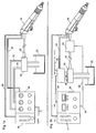
- Fig. 1a shows schematically a powder coating system with a control system according to the prior art.
- the main components this coating system are an analog Control unit 10, a delivery injector 12 and a spray gun 14.
- Control unit 10 receives compressed air via line 11 and sets the air pressure for the conveying air and the dosing air of the delivery injector 12 and the atomizing air Spray gun 14 and displays these sizes.
- the funding and the dosing air are via a conveying air line 16 and a metering air line 18 fed to the delivery injector 12, which coating powder from a powder storage container 20 sucks and creates a powder-air mixture that over a feed line 22 is transported to the spray gun 14 becomes.
- the atomizing air is directly through an atomizing air line 24 directed from the control unit to the spray gun.
- the powder storage container has a (not shown) Fluidizing device and a fluidizing air inlet.
- control unit 10 there is also a current / voltage control part 26 housed the one via a line 28
- Control signal to the spray gun 14 transmits the for the electrostatic powder coating potential to create.
- operating the powder coating system described essentially have to set seven operating parameters and be monitored, of which the coating quality is dependent and partly in interaction with each other stand. These operating parameters are: conveying air, dosing air, Atomizing air, high voltage and current of the high voltage generator, Powder level in the storage container and fluidizing air.
- the tax system essentially consists of a digital control device 30 with a current / voltage control part 26, a feed injector 32, a spray gun 34, a powder quantity measuring device in the form of a powder quantity sensor 36 and a powder quantity control device in Form of a proportional valve unit 38.
- the digital control device 30 has a control signal output 40 for delivering control signals to the proportional valve unit 38 and a voltage signal output 42 for delivering a Voltage control signal to the spray gun 34.
- the spray gun contains a high voltage generator (not shown).
- the control device has a signal input 44 for a feedback signal from the powder quantity sensor 36.
- the Proportional valve unit 38 from an air supply line 46 fed, which is in a conveyor air line 48 and a Dosing air line 50 branches to the output from the injector Adjust or regulate the powder-air mixture.
- the control system of the powder coating system shown in FIG. 1b can by converting a known system 1a can be constructed by the analog control device 10 is replaced by the digital control unit 30, the proportional valve unit 38 on or near the injector 32 is attached and the powder quantity sensor 36 in the powder feed 52 for each spray gun 34 as close as possible the spray gun is installed.
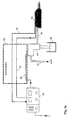
- FIG. 2a schematically shows a further embodiment of the present invention in which the proportional valve unit into the injector 64 and the powder quantity sensor into the Spray gun 66 are integrated.
- a technically equivalent Result is obtained when the proportional valve unit and the powder quantity sensor in the immediate vicinity of the Injector 64 and the spray gun 66 are arranged.
- Fig. 2a is the digital controller 60 which is essentially corresponds to the control device 30 of FIG. 1b, only shown schematically.
- the control device 60 is via a gun bus 62 with the injector 64 and the spray gun 66 connected.
- the injector 64 has only a central air supply 74 and only one input for electronic control. Of the Injector 64 leads a powder feed line 76 to the spray gun 66
- Fig. 2a The function of the system shown in Fig. 2a is essentially equal to that of Fig. 1b. However, this feature will achieved with fewer individual components, which increases the effort for excluding signal lines and laying of the air lines further reduced.
- FIG. 2b Another embodiment variant of the system according to the invention is shown in Figure 2b, wherein in Figs. 2a and 2b the same components with the same reference numerals are.
- Fig. 2b In the control system according to Fig. 2b are for signal transmission no individual lines provided; the whole electrical signal transmission takes place via the gun bus 62, 62 '. This ranges from control unit 60 to injector 64 and from there to the spray gun 66.
- the signal transmission via gun bus 62 is bidirectional.
- Gun bus 62, 62 ' is preferably an LON bus, and the proportional valve unit and the powder quantity sensor are configured as LON nodes, the digitally encoded signals receive and transmit as below with reference to Figure 5 is described in more detail.
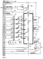
- FIG. 3 Another embodiment of a control system for a Powder coating installation according to the invention is shown in FIG. 3 shown.
- Fig. 3 there are several (five) coating modules on the right side one digital control unit each 60, an injector 64 with an integrated control unit and a spray gun 66 with an integrated powder quantity sensor shown, which are connected via a gun bus 62.
- These coating modules 60 to 66 form autonomous, self-regulating Functional units, which their respective control signals received from the digital controller 60. Setpoints and information about the operating status necessary for the control the coating unit receives the control unit 60 via an internal bus 80.
- a number of coating modules 60 are connected via the internal bus to 66 with each other and with a central control module 82 and connected to other components of the system. Additional, modules that can be connected to the internal bus in addition to the central control module 82, a slave control module 84, a gap control module 86, a powder level control module 88 Position control module 90 and a motion control module 92 be.
- the bus 80 is preferably designed as a LON bus.
- the functions of the individual modules correspond essentially those of the known analog systems with the The difference is that the modules are configured as LON nodes and have a LON interface so that they can be connected to the LON bus 80 can be connected.
- the control module 82 is responsible for the central supply of the entire powder coating system with electrical power (Arrow 92 and indicator lamp 98) and compressed air (arrow 93 and Indicator lamp 94). Indicator lamp 96 shows the off / on state of the main motion functions of the spray guns 66. Further the central control module 82 has an emergency stop switch 99 with alarm so that the entire system in the event of a fault to be able to switch off from a central point.
- the central control module 82 may have a memory for the recording of past process parameters and the Storage of setpoints included from memory can be accessed.
- the slave control module 84 contains an additional power supply and is used in the event of an expansion of the overall system.
- the central control module 82 e.g. up to 24 spray guns supply with electrical power and compressed air. If more than 24 spray guns within one powder coating system the slave control module takes over 84 their supply, with the emergency stop function for the entire system, however, at the central one Control module 82 remains.
- the gap control module 86 is used to switch off the spray guns in the gaps between those at the coating line conveyed workpieces 200 or workpiece parts.
- the Powder level control module 88 monitors the level in one Powder storage container and provides this for the even Powder delivery to a constant value.
- the position control module 90 controls the position of the spray guns in the z direction depending on the thickness of the coating Workpiece 200 to always an optimal distance from spray gun 66 to comply with workpiece 200.
- the motion control module 92 controls the up and down movement of the Spray gun 66 depending on the height of the to be coated Workpiece 200.
- the system shown in Fig. 3 is due to its bus structure easily expandable and changeable because both more Coating modules as well as other additional modules the bus can be coupled.
- the individual components, configured as LON nodes can be in the Register the system yourself, recognize other system components, adjust to them and communicate with them. At Coupling or uncoupling individual components is not reprogramming of the other components necessary because each LON node inform the LON network of its function and that for it certain, coded signals can automatically recognize.
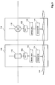
- FIG. 4 shows a further expanded powder coating system, in the case of a third or external bus 100 further assemblies are coupled in larger powder coating systems occurrence. These other assemblies are also connected to the central bus via the external bus 100 Control module 82 connected. They include in the shown Example a powder center 102 with a powder storage container 104 and a powder level probe 105, a cleaning control module 106 for automatic cabin cleaning, one Layer thickness measuring and control device 108 and an air quantity control device 109 for a powder recovery system 110, a part detection module 111 and a conveyor clock 112.
- the central control module 82 connects the external and the internal bus, which in function and structure essentially are the same.
- External bus 100 is also preferably one LON bus.
- the operation of the powder coating system shown in Figure 4 works like this.
- a workpiece 200 approaches the Coating booth 120 and is by the parts recognition module 111 recognized.
- the parts recognition module 111 detects both that a workpiece 200 is approaching as well as the type in particular the size and shape of the workpiece 200. This information are put on the bus 100, 80 and stand immediately for all other components of the powder coating system to disposal. This will make the different Components such as spray guns 66, digital control device 60, Motion control module 92, position control module 90 etc. in Willingness.
- the speed of the Workpiece detected and also placed on the bus 100, 80.
- the various components of the system "know" when the workpiece 200 arrives.
- Spray gun 66-1 When workpiece 200 arrives, the first begins Spray gun 66-1 to spray, due to the parts and Speed information is known, which position in z direction, i.e. what distance to workpiece 200 the Spray gun must have what stroke movement the spray gun must make where there are workpiece gaps where the spray gun is to be switched off, etc. That of the spray gun 66-1 assigned digital control unit gives the information that the gun sprays or does not spray onto bus 80, so that the individual spray guns 66-1 to 66-n synchronized can be. Within each coating unit 60-66 the amount of powder applied is regulated, depending on different colors and colors of the workpiece to be coated Various setpoints for the amount of powder applied are specified can be. These specifications are in the central Control module 82 or any digital control device 62 stored, and they become dependent on the recognized workpiece 200 accessed.
- the external Bus 100 automatically controls the powder layer thickness the workpiece 200 with the aid of the layer thickness control module 108 and a layer thickness sensor 107 possible.
- the air flow control device 109 can be the suction system 114 can be controlled to the efficiency of the recovery system 110 to optimize if depending on the shape of the excess workpiece to be coated Powder must be suctioned off.
- Via the cleaning control module 106 and an automatic cleaning device 116 is a fully automatic cleaning of the cabin system programmable possible.
- LON nodes 112, 114 are from a sensor like that Air quantity sensor 116 or an actuator (actuator), such as the Proportional valve 118, an application-specific electronics 120, a neuron chip 122 and an adapter or Transceiver 124 built.
- the transceiver 124 serves as an interface for connection of the respective LON node with the LON bus, which here as Two-wire communication line 126 is shown.
- the Neuron chip 122 forms the interface between the Transceiver and application-specific electronics 120 and has the function of configuring LON nodes 112 or 114 that always the same data format and data transfer protocol for communication between each LON node and the digital control unit 30 or the other accounts of a LON network can be used.
- an 8-bit microcontroller is available stand in the language compatible with ANSI-C Neuron-C can be programmed, so that intelligence in every node can be made available on site.
- the air flow sensor node 112 and the proportional valve node 114 the other, to whom internal or the external bus 80, 100 connected components the powder coating system so that at least for each group from related similar ones Node a uniform bus data protocol can be used can.
- control system offers a fully automatic Control of the essentials for the coating Sizes, with constant automatic system optimization the need is minimized to have expert knowledge at the System setting.
- the automatic layer thickness control enables compliance very narrow tolerance values.
- the modular system structure enables the customer to put together a system according to his wishes and relative expand without problems.
Abstract
Description
- Fig. 1a
- zeigt schematisch ein Pulversprühsystem nach dem Stand der Technik;
- Fig. 1b
- zeigt ein Steuersystem nach einer ersten Ausführungsform der Erfindung;
- Fig. 2a
- zeigt ein Steuersystem nach einer zweiten Ausführungsform der Erfindung;
- Fig. 2b
- zeigt eine modifizierte Ausführungsform des Steuersystems der Fig. 2a;
- Fig. 3
- zeigt eine Pulverbeschichtungsanlage mit einem Steuersystem der Erfindung;
- Fig. 4
- zeigt eine erweiterte Pulverbeschichtungsanlage mit einem Steuersystem der Erfindung; und
- Fig. 5
- zeigt Beispiele für zwei Knoten des erfindungsgemäßen Steuersystems.
Claims (15)
- Steuersystem einer Beschichtungsanlage für ein Beschichtungsmedium, wie Pulver oder Naßlack, mit mindestens einem Beschichtungsgerät, bei der dem oder jedem Beschichtungsgerät (34, 66) eine Mengenmeßeinrichtung (36) zur Bestimmung der dem Beschichtungsgerät zugeführten Menge des Beschichtungsmediums, eine Mengensteuereinrichtung (38) zur Einstellung der von dem Beschichtungsgerät abzugebenden Menge des Beschichtungsmediums und ein digitales Steuergerät (60) zur Steuerung des Betriebs des Beschichtungsgerätes zugeordnet sind, wobei die Mengenmefleinrichtung (36) und die Mengensteuereinrichtung (38) jeweils einen Netzwerkknoten (112, 114) bilden, der über eine Busstruktur (62) mit dem digitalen Steuergerät (60) verbunden ist, wobei die Netzwerkknoten LON-Knoten sind.
- System nach Anspruch 1, dadurch gekennzeichnet, daß jeder Netzwerk-Knoten einen Sensor (116) und/oder ein Stellglied (118), eine anwendungsspezifische Elektronik (120), einen Steuerbaustein (122), und eine Schnittstelle (124) für die Verbindung mit der Busstruktur (62, 80; 126) aufweist.
- System nach Anspruch 1 oder 2, dadurch gekennzeichnet, daß die Mengenmeßeinrichtung (36) und die Mengensteuereinrichtung über einen ersten LON-Bus (62) mit dem digitalen Steuergerät (60) verbunden und ansteuerbar sind.
- System nach einem der vorhergehenden Ansprüche, dadurch gekennzeichnet, daß mehrere Beschichtungsgeräte (66) vorhanden sind, daß jeweils die zu einem Beschichtungsgerät gehörende Mengenmeßeinrichtung, Mengensteuereinrichtung und das digitale Steuergerät (60) über einen ersten LON-Bus (62) miteinander verbunden sind und einen weiteren LON-Knoten bilden, der über einen zweiten LON-Bus (80) mit einer zentralen Steuereinheit (82) verbunden ist.
- System nach Anspruch 4, dadurch gekennzeichnet, daß die zentrale Steuereinheit (82) eine zentrale Steuereinrichtung für die Versorgung der Beschichtungsanlage mit Druckluft und elektrischem Strom und eine Notabschalteinrichtung aufweist.
- System nach einem der vorhergehenden Ansprüche, gekennzeichnet durch eine Anzeigeeinrichtung für einen oder mehrere Betriebsparameter.
- System nach einem der vorhergehenden Ansprüche, gekennzeichnet durch folgende weitere Komponenten, welche mit der Busstruktur (62, 80; 126) verbindbar sind: eine Lückensteuereinrichtung (86), eine Vorratssteuereinrichtung (88) für das Beschichtungsmedium, eine Positionssteuereinrichtung (90) und eine Bewegungssteuereinrichtung (92) für die Beschichtungsgeräte (66) und/oder eine Slave-Steuereinrichtung (84), wobei die weiteren Komponenten als Netzwerk-Knoten ausgebildet sind.
- System nach einem der vorhergehenden Ansprüche gekennzeichnet durch folgende weitere Komponenten, welche mit der Busstruktur (62, 80; 126) verbindbar sind: eine Rückgewinnungs-Steuereinrichtung und eine Zufuhr-Steuereinrichtung für das Beschichtungsmedium, eine Teileerkennungseinrichtung, eine Fördertakt-Steuereinrichtung, eine Reinigungseinrichtung und/oder eine Schichtdickenmeßeinrichtung, wobei die weiteren Komponenten als Netzwerk-Knoten ausgebildet sind.
- System nach einem der vorhergehenden Ansprüche gekennzeichnet durch eine Speichereinrichtung für die Betriebsparameter.
- System nach einem der vorhergehenden Ansprüche gekennzeichnet durch einen Programmierrechner, der mit der Busstruktur koppelbar ist, um Sollwerte für die Betriebsparameter einzugeben und/oder den Betrieb der Beschichtungsanlage zu überwachen.
- System nach einem der vorhergehenden Ansprüche, dadurch gekennzeichnet, daß die Mengenmeßeinrichtung in das Beschichtungsgerät integriert ist oder in der Nähe des Beschichtungsgerätes angeordnet ist.
- Elektrostatische Pulverbeschichtungsanlage mit mindestens einem Beschichtungsgerät für ein Beschichtungsmedium, wie Pulver oder Naßlack, und mit einem Steuersystem nach einem der vorhergehenden Ansprüche.
- Anlage nach Anspruch 12, dadurch gekennzeichnet, daß die Betriebsparameter Luftmenge, insbesondere der Förderluft, der Dosierluft und der Zerstäuberluft, Pulvermenge und -geschwindigkeit sowie Strom- und Spannungswerte umfassen.
- Anlage nach Anspruch 12 oder 13, dadurch gekennzeichnet, daß die Mengensteuereinrichtung (64) eine Luftzufuhrleitung (46), eine Proportionalventileinheit (38) und einen Injektor (32) zur Regelung de Pulvermenge für das jeweilige Beschichtungsgerät aufweist.
- Anlage nach Anspruch 14, dadurch gekennzeichnet, daß die Proportionalventileinheit (38) wenigstens zwei Proportionalventile für die Einstellung der Förderluft und der Dosierluft des jeweiligen Beschichtungsgerätes (34) aufweist.
Applications Claiming Priority (2)
| Application Number | Priority Date | Filing Date | Title |
|---|---|---|---|
| DE19738141A DE19738141C2 (de) | 1997-09-01 | 1997-09-01 | Steuersystem einer Beschichtungsanlage mit einer LON-Busstruktur |
| DE19738141 | 1997-09-01 |
Publications (2)
| Publication Number | Publication Date |
|---|---|
| EP0899018A1 true EP0899018A1 (de) | 1999-03-03 |
| EP0899018B1 EP0899018B1 (de) | 2002-05-22 |
Family
ID=7840842
Family Applications (1)
| Application Number | Title | Priority Date | Filing Date |
|---|---|---|---|
| EP98113512A Expired - Lifetime EP0899018B1 (de) | 1997-09-01 | 1998-07-20 | Netzwerk zum Steuern einer Beschichtungsanlage |
Country Status (4)
| Country | Link |
|---|---|
| US (1) | US6059884A (de) |
| EP (1) | EP0899018B1 (de) |
| JP (1) | JPH11169763A (de) |
| DE (2) | DE19738141C2 (de) |
Cited By (7)
| Publication number | Priority date | Publication date | Assignee | Title |
|---|---|---|---|---|
| US6051280A (en) * | 1997-09-01 | 2000-04-18 | Wagner International Ag | Method of controlling an electrostatic coating device and an electrostatic coating system |
| US6068877A (en) * | 1997-09-01 | 2000-05-30 | Wagner International Ag | Method of detecting workpieces in an electrostatic coating system |
| US6476277B2 (en) | 2000-07-28 | 2002-11-05 | Bayer Aktiengesellschafter | Process for preparing hydroxyaromatics |
| WO2006095237A1 (en) | 2005-03-07 | 2006-09-14 | Itw Gema Ag | Electronic spray coating control device |
| WO2009083087A1 (de) * | 2007-12-21 | 2009-07-09 | Dürr Systems GmbH | Testverfahren und testgerät zur funktionsprüfung einer lackiereinrichtung |
| EP2368642A1 (de) * | 2010-01-19 | 2011-09-28 | Thomas Dipl.-Ing. Pilz | Belüftungsvorrichtung für Spritzlackieranlagen |
| WO2015169433A1 (de) * | 2014-05-07 | 2015-11-12 | Dürr Systems GmbH | Beschichtungsanlage zur beschichtung von bauteilen, insbesondere zur lackierung von kraftfahrzeugkarosseriebauteilen |
Families Citing this family (15)
| Publication number | Priority date | Publication date | Assignee | Title |
|---|---|---|---|---|
| DE19753660C2 (de) * | 1997-12-03 | 2001-01-25 | Wagner Internat Ag Altstaetten | Verfahren und Einrichtung zum Aufbringen eines Trennmittels auf eine Spritzgußform |
| DE19936393A1 (de) * | 1999-08-03 | 2001-02-08 | Volkswagen Ag | Verfahren und Vorrichtung zum Auf- bzw. Einbringen eines Werkstoffes auf bzw. in eine Oberfläche |
| DE10133744A1 (de) * | 2001-07-11 | 2003-01-30 | Hammelmann Paul Maschf | Spritzpistole |
| DE10239351B4 (de) * | 2002-08-28 | 2006-07-27 | Amtec Kistler Gmbh | Vorrichtung zum Auftragen eines Beschichtungsmittels |
| DE10335420A1 (de) * | 2003-08-02 | 2005-02-17 | ITW Oberflächentechnik GmbH & Co. KG | Spritzbeschichtungseinrichtung |
| DE102009029821A1 (de) | 2009-06-18 | 2010-12-23 | Focke & Co.(Gmbh & Co. Kg) | Verfahren zum Betreiben eines Beleimungssystems |
| DE102011004024A1 (de) * | 2011-02-14 | 2012-08-16 | Illinois Tool Works Inc. | Steuervorrichtung für eine Pulversprühbeschichtungseinrichtung |
| DE102011103326B4 (de) | 2011-05-27 | 2014-08-07 | Siempelkamp Maschinen- Und Anlagenbau Gmbh & Co. Kg | Vorrichtung und Verfahren zum Beleimen von Fasern |
| EP2650052B2 (de) * | 2012-04-13 | 2021-01-27 | J. Wagner AG | Pulverbechersprühpistole und Sprühbeschichtungsvorrichtung mit einer Pulverbechersprühpistole |
| DE102013014669A1 (de) * | 2013-09-03 | 2015-03-05 | Eisenmann Ag | Einrichtung zum Bereitstellen eines Applikationsmaterials |
| WO2016127106A1 (en) | 2015-02-05 | 2016-08-11 | Carlisle Fluid Technologies, Inc. | Spray tool system |
| US10324428B2 (en) | 2015-02-12 | 2019-06-18 | Carlisle Fluid Technologies, Inc. | Intra-shop connectivity system |
| US11273462B2 (en) | 2015-11-26 | 2022-03-15 | Carlisle Fluid Technologies, Inc. | Sprayer system |
| US10434525B1 (en) * | 2016-02-09 | 2019-10-08 | Steven C. Cooper | Electrostatic liquid sprayer usage tracking and certification status control system |
| CN113499873A (zh) * | 2021-07-23 | 2021-10-15 | 张同胜 | 一种多系统集成喷粉机及其使用方法 |
Citations (4)
| Publication number | Priority date | Publication date | Assignee | Title |
|---|---|---|---|---|
| GB2070281A (en) * | 1980-02-27 | 1981-09-03 | Champion Spark Plug Co | Control of coating apparatus |
| US4894252A (en) * | 1988-11-30 | 1990-01-16 | Ransburg Corporation | Coating material orifice clogging indication method and apparatus |
| EP0706102A2 (de) * | 1994-10-05 | 1996-04-10 | Nordson Corporation | Verteiltes Steuersystem für ein Pulverauftragesystem |
| US5739429A (en) * | 1995-07-13 | 1998-04-14 | Nordson Corporation | Powder coating system incorporating improved method and apparatus for monitoring flow rate of entrained particulate flow |
Family Cites Families (7)
| Publication number | Priority date | Publication date | Assignee | Title |
|---|---|---|---|---|
| DE7909134U1 (de) * | 1979-03-30 | 1979-07-05 | Siemens Ag, 1000 Berlin Und 8000 Muenchen | Halterung fuer eine elektrische spule |
| US4614300A (en) * | 1982-04-19 | 1986-09-30 | E. I. Du Pont De Nemours And Company | Computerized spray machine |
| DE3913584A1 (de) * | 1989-04-25 | 1990-10-31 | Walter Westenberger | Verfahren und anordnung zur ueberwachung des spritzvorgangs bei spritzpistolen |
| DE4231766A1 (de) * | 1992-09-23 | 1994-03-24 | Licentia Gmbh | Verfahren zur Eingabe und Anzeige der Einstellungsparameter einer Vorrichtung zum Beschichten von Gegenständen |
| IT1257689B (it) * | 1992-11-20 | 1996-02-01 | Impianto di verniciatura a polveri con cabina a sezione variabile | |
| DE4325044C2 (de) * | 1993-07-26 | 2002-07-18 | Itw Gema Ag | Pulverfördervorrichtung, insbesondere für Beschichtungspulver |
| DE4339748A1 (de) * | 1993-11-22 | 1995-05-24 | Licentia Gmbh | Verfahren und Anordnung zum Steuern einer Vielzahl von Spritzwerkzeugen für die Oberflächenbeschichtung von Fahrzeugen oder deren Teile |
-
1997
- 1997-09-01 DE DE19738141A patent/DE19738141C2/de not_active Expired - Fee Related
-
1998
- 1998-06-29 US US09/106,482 patent/US6059884A/en not_active Expired - Fee Related
- 1998-07-20 EP EP98113512A patent/EP0899018B1/de not_active Expired - Lifetime
- 1998-07-20 DE DE59804178T patent/DE59804178D1/de not_active Expired - Fee Related
- 1998-09-01 JP JP10247552A patent/JPH11169763A/ja active Pending
Patent Citations (4)
| Publication number | Priority date | Publication date | Assignee | Title |
|---|---|---|---|---|
| GB2070281A (en) * | 1980-02-27 | 1981-09-03 | Champion Spark Plug Co | Control of coating apparatus |
| US4894252A (en) * | 1988-11-30 | 1990-01-16 | Ransburg Corporation | Coating material orifice clogging indication method and apparatus |
| EP0706102A2 (de) * | 1994-10-05 | 1996-04-10 | Nordson Corporation | Verteiltes Steuersystem für ein Pulverauftragesystem |
| US5739429A (en) * | 1995-07-13 | 1998-04-14 | Nordson Corporation | Powder coating system incorporating improved method and apparatus for monitoring flow rate of entrained particulate flow |
Cited By (10)
| Publication number | Priority date | Publication date | Assignee | Title |
|---|---|---|---|---|
| US6051280A (en) * | 1997-09-01 | 2000-04-18 | Wagner International Ag | Method of controlling an electrostatic coating device and an electrostatic coating system |
| US6068877A (en) * | 1997-09-01 | 2000-05-30 | Wagner International Ag | Method of detecting workpieces in an electrostatic coating system |
| US6476277B2 (en) | 2000-07-28 | 2002-11-05 | Bayer Aktiengesellschafter | Process for preparing hydroxyaromatics |
| WO2006095237A1 (en) | 2005-03-07 | 2006-09-14 | Itw Gema Ag | Electronic spray coating control device |
| US8601977B2 (en) | 2005-03-07 | 2013-12-10 | Itw Gema Gmbh | Spray coating control device |
| WO2009083087A1 (de) * | 2007-12-21 | 2009-07-09 | Dürr Systems GmbH | Testverfahren und testgerät zur funktionsprüfung einer lackiereinrichtung |
| US8567694B2 (en) | 2007-12-21 | 2013-10-29 | Durr Sysems GmbH | Test method and test apparatus for checking the function of a painting device |
| EP2368642A1 (de) * | 2010-01-19 | 2011-09-28 | Thomas Dipl.-Ing. Pilz | Belüftungsvorrichtung für Spritzlackieranlagen |
| WO2015169433A1 (de) * | 2014-05-07 | 2015-11-12 | Dürr Systems GmbH | Beschichtungsanlage zur beschichtung von bauteilen, insbesondere zur lackierung von kraftfahrzeugkarosseriebauteilen |
| US10369583B2 (en) | 2014-05-07 | 2019-08-06 | Dürr Systems Ag | Centrally controlled coating system for painting motor vehicle body components |
Also Published As
| Publication number | Publication date |
|---|---|
| JPH11169763A (ja) | 1999-06-29 |
| EP0899018B1 (de) | 2002-05-22 |
| DE19738141A1 (de) | 1999-03-18 |
| DE19738141C2 (de) | 2003-06-05 |
| US6059884A (en) | 2000-05-09 |
| DE59804178D1 (de) | 2002-06-27 |
Similar Documents
| Publication | Publication Date | Title |
|---|---|---|
| EP0899018B1 (de) | Netzwerk zum Steuern einer Beschichtungsanlage | |
| DE69524707T3 (de) | Verteiltes Steuersystem für ein Pulverauftragesystem | |
| EP0824231B1 (de) | Fertigungsanlage | |
| EP2442970A1 (de) | Verfahren zum betreiben eines beleimungssystems | |
| EP2455310A1 (de) | Staufördersystem mit zwei Kommunikationssystemen | |
| WO2001069094A1 (de) | Einrichtung zur steuerung eines hydraulischen aktuators | |
| EP2318892B1 (de) | Funkbasierte aktivierung und deaktivierung eines energielosen standby-betriebs von automatisierungssystemen | |
| DE102017213589A1 (de) | Schmiersystem mit einem Signalübertragungselement | |
| WO2013044964A1 (de) | Vorrichtung zur energieeffizienten steuerung einer anlage und verfahren hierzu | |
| WO2014072340A1 (de) | Produktionsanlage eines chemischen oder pharmazeutischen produktes | |
| EP0413044B1 (de) | Flexibles Automatisierungssystem für variable industrielle Prozesse | |
| EP0825502B1 (de) | Steuerungssystem | |
| EP1903530B1 (de) | Anordnung mit Vakuumgerät und Verfahren zu deren Betrieb | |
| DE29724794U1 (de) | Steuersystem einer Beschichtungsanlage mit einer LON-Busstruktur | |
| DE102017120545B4 (de) | Ventilbaugruppe für eine Spritzmaschine | |
| DE19906695A1 (de) | Verfahren zur automatischen Dezentralisierung von Programmen in Steuerungseinrichtungen und zur Verteilung von Intelligenz | |
| DE102014222508A1 (de) | Modul für eine prozesstechnische Anlage und Verfahren zur Steuerung einer prozesstechnischen Anlage | |
| EP0809162B1 (de) | Verfahren zur Prozesssteuerung und Gerätesteuersystem | |
| DE102018005149A1 (de) | Analog gesteuerte Fördervorrichtung mit Datenauslesung | |
| WO2008031695A1 (de) | Kommunikationsnetz mit haupteilnehmern und topologieserver | |
| EP3941858B1 (de) | Vorrichtung und verfahren zur verbesserung der kommunikation von modularen fördersystemen | |
| EP3899678A1 (de) | Automatisierungseinrichtung, anlagenmodul und verfahren zur lokalen steuerung einer technischen hardware | |
| EP4200678A1 (de) | Feldgerät, messanordnung sowie zum betreiben eins solchen feldgeräts | |
| DE102018123074A1 (de) | Steuerungsanordnung für technische Anlagen, die mehrere gleichartige Aktuatoren umfassen | |
| WO2016166333A1 (de) | Vorrichtung zum auftragen von fluiden |
Legal Events
| Date | Code | Title | Description |
|---|---|---|---|
| PUAI | Public reference made under article 153(3) epc to a published international application that has entered the european phase |
Free format text: ORIGINAL CODE: 0009012 |
|
| AK | Designated contracting states |
Kind code of ref document: A1 Designated state(s): CH DE FR GB IT LI |
|
| AX | Request for extension of the european patent |
Free format text: AL;LT;LV;MK;RO;SI |
|
| 17P | Request for examination filed |
Effective date: 19990804 |
|
| AKX | Designation fees paid |
Free format text: CH DE FR GB IT LI |
|
| 17Q | First examination report despatched |
Effective date: 20001130 |
|
| GRAG | Despatch of communication of intention to grant |
Free format text: ORIGINAL CODE: EPIDOS AGRA |
|
| GRAG | Despatch of communication of intention to grant |
Free format text: ORIGINAL CODE: EPIDOS AGRA |
|
| GRAH | Despatch of communication of intention to grant a patent |
Free format text: ORIGINAL CODE: EPIDOS IGRA |
|
| GRAH | Despatch of communication of intention to grant a patent |
Free format text: ORIGINAL CODE: EPIDOS IGRA |
|
| GRAA | (expected) grant |
Free format text: ORIGINAL CODE: 0009210 |
|
| REG | Reference to a national code |
Ref country code: GB Ref legal event code: FG4D Free format text: NOT ENGLISH |
|
| REG | Reference to a national code |
Ref country code: CH Ref legal event code: EP |
|
| GBT | Gb: translation of ep patent filed (gb section 77(6)(a)/1977) |
Effective date: 20020524 |
|
| REF | Corresponds to: |
Ref document number: 59804178 Country of ref document: DE Date of ref document: 20020627 |
|
| ET | Fr: translation filed | ||
| PLBQ | Unpublished change to opponent data |
Free format text: ORIGINAL CODE: EPIDOS OPPO |
|
| PLBI | Opposition filed |
Free format text: ORIGINAL CODE: 0009260 |
|
| PLBF | Reply of patent proprietor to notice(s) of opposition |
Free format text: ORIGINAL CODE: EPIDOS OBSO |
|
| 26 | Opposition filed |
Opponent name: ITW GEMA AG Effective date: 20030205 |
|
| PLBB | Reply of patent proprietor to notice(s) of opposition received |
Free format text: ORIGINAL CODE: EPIDOSNOBS3 |
|
| REG | Reference to a national code |
Ref country code: CH Ref legal event code: NV Representative=s name: ISLER & PEDRAZZINI AG |
|
| PGFP | Annual fee paid to national office [announced via postgrant information from national office to epo] |
Ref country code: GB Payment date: 20040721 Year of fee payment: 7 |
|
| PGFP | Annual fee paid to national office [announced via postgrant information from national office to epo] |
Ref country code: FR Payment date: 20040727 Year of fee payment: 7 |
|
| PGFP | Annual fee paid to national office [announced via postgrant information from national office to epo] |
Ref country code: CH Payment date: 20040729 Year of fee payment: 7 |
|
| PGFP | Annual fee paid to national office [announced via postgrant information from national office to epo] |
Ref country code: DE Payment date: 20040804 Year of fee payment: 7 |
|
| PLCK | Communication despatched that opposition was rejected |
Free format text: ORIGINAL CODE: EPIDOSNREJ1 |
|
| PLBN | Opposition rejected |
Free format text: ORIGINAL CODE: 0009273 |
|
| STAA | Information on the status of an ep patent application or granted ep patent |
Free format text: STATUS: OPPOSITION REJECTED |
|
| 27O | Opposition rejected |
Effective date: 20041020 |
|
| PG25 | Lapsed in a contracting state [announced via postgrant information from national office to epo] |
Ref country code: IT Free format text: LAPSE BECAUSE OF NON-PAYMENT OF DUE FEES Effective date: 20050720 Ref country code: GB Free format text: LAPSE BECAUSE OF NON-PAYMENT OF DUE FEES Effective date: 20050720 |
|
| PG25 | Lapsed in a contracting state [announced via postgrant information from national office to epo] |
Ref country code: LI Free format text: LAPSE BECAUSE OF NON-PAYMENT OF DUE FEES Effective date: 20050731 Ref country code: CH Free format text: LAPSE BECAUSE OF NON-PAYMENT OF DUE FEES Effective date: 20050731 |
|
| PG25 | Lapsed in a contracting state [announced via postgrant information from national office to epo] |
Ref country code: DE Free format text: LAPSE BECAUSE OF NON-PAYMENT OF DUE FEES Effective date: 20060201 |
|
| REG | Reference to a national code |
Ref country code: CH Ref legal event code: PL |
|
| GBPC | Gb: european patent ceased through non-payment of renewal fee |
Effective date: 20050720 |
|
| PG25 | Lapsed in a contracting state [announced via postgrant information from national office to epo] |
Ref country code: FR Free format text: LAPSE BECAUSE OF NON-PAYMENT OF DUE FEES Effective date: 20060331 |
|
| REG | Reference to a national code |
Ref country code: FR Ref legal event code: ST Effective date: 20060331 |
|
| PLAB | Opposition data, opponent's data or that of the opponent's representative modified |
Free format text: ORIGINAL CODE: 0009299OPPO |