EP0898060B1 - Ölmodul für Brennkraftmaschinen - Google Patents
Ölmodul für Brennkraftmaschinen Download PDFInfo
- Publication number
- EP0898060B1 EP0898060B1 EP98114489A EP98114489A EP0898060B1 EP 0898060 B1 EP0898060 B1 EP 0898060B1 EP 98114489 A EP98114489 A EP 98114489A EP 98114489 A EP98114489 A EP 98114489A EP 0898060 B1 EP0898060 B1 EP 0898060B1
- Authority
- EP
- European Patent Office
- Prior art keywords
- oil
- housing
- module
- filter
- ventilation system
- Prior art date
- Legal status (The legal status is an assumption and is not a legal conclusion. Google has not performed a legal analysis and makes no representation as to the accuracy of the status listed.)
- Revoked
Links
Images


Classifications
-
- F—MECHANICAL ENGINEERING; LIGHTING; HEATING; WEAPONS; BLASTING
- F01—MACHINES OR ENGINES IN GENERAL; ENGINE PLANTS IN GENERAL; STEAM ENGINES
- F01M—LUBRICATING OF MACHINES OR ENGINES IN GENERAL; LUBRICATING INTERNAL COMBUSTION ENGINES; CRANKCASE VENTILATING
- F01M13/00—Crankcase ventilating or breathing
- F01M13/04—Crankcase ventilating or breathing having means for purifying air before leaving crankcase, e.g. removing oil
-
- F—MECHANICAL ENGINEERING; LIGHTING; HEATING; WEAPONS; BLASTING
- F01—MACHINES OR ENGINES IN GENERAL; ENGINE PLANTS IN GENERAL; STEAM ENGINES
- F01M—LUBRICATING OF MACHINES OR ENGINES IN GENERAL; LUBRICATING INTERNAL COMBUSTION ENGINES; CRANKCASE VENTILATING
- F01M11/00—Component parts, details or accessories, not provided for in, or of interest apart from, groups F01M1/00 - F01M9/00
- F01M11/03—Mounting or connecting of lubricant purifying means relative to the machine or engine; Details of lubricant purifying means
Definitions
- the invention relates to an oil module for internal combustion engines.
- the lubricant circuit of internal combustion engines has one oil filter and one Oil cooler, see e.g. GB 2 298 037, the crankcase must also have a ventilation system Oil separators that separate oil and air and the separated oil into the Crankcase returns. These individual components are common assembled separately, which leads to relatively high assembly costs. It is also high the total space requirement of the individually arranged on the internal combustion engine Components.
- the invention has for its object the assembly costs and total space requirements Reduce individual components.
- the oil module which has all the components in or on its housing represents a structural unit that as a whole to the internal combustion engine, for example can be flanged to the crankcase.
- the unit stands out from the smallest possible construction volume.
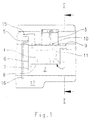
- Fig. 1 shows an oil module 1, which laterally as a structural unit on a crankcase 2 an internal combustion engine is attached.
- the oil module 1 combines two parts executed oil filter 3, an oil cooler 4 and a ventilation system 5 with oil separator.
- the oil cooler 4 is completely enclosed by a housing 6.
- the Oil filter 3 and the ventilation system with oil separator are directly connected to the Housing 6 attached, so that there is a structural unit, which as a whole to the Internal combustion engine, for example laterally to the crankcase 2 of the internal combustion engine can be flanged.
- the housing 6 is at one end with a cooling water inlet 7 and an oil inlet 8 and at the opposite end with a cooling water outlet 9 and an oil spill 10 to the oil filter 3.
- the cooling water flows around the oil cooler 4 full length and absorbs the heat of the lubricating oil.
- the oil flows through the oil filter 3 and passes through an oil return channel 11 to the lubrication points.
- the ventilation system 5 with oil separator is also directly on the housing 6 connected.
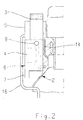
- the oil-containing air in the crankcase 2 enters from the crankcase 2 a cross section 14, see FIG. 2, in the ventilation system 5 with Oil separator opens where air and oil are separated.
- the de-oiled air can pass through a Air channel 15 escape, while the oil via an oil return channel 16 in a Oil pan 17 flows back.
- the mouth of the oil return channel 16 is below that Oil level in the oil pan 17.
- Fig. 2 shows a section II-II through the housing 6 with an adjacent crankcase 2.
- the oil filter 3 and ventilation system 5 with oil separator Mounted on the housing 6 and connected to it are the oil filter 3 and ventilation system 5 with oil separator.
- the oil cooler 4 is completely from the housing 6 enclosed.
- the housing 6 together with the oil filter 3, oil cooler 4 and ventilation system 5 According to the invention, the oil separator thus forms a structural unit, which is immediate can be flanged to the side of the crankcase 2 of the internal combustion engine Cooling water, which is the oil cooler 4, is supplied via the cooling water inlet 7 completely flows around.
- the cooling water outlet 9 can also be seen from FIG. 1. That in Venting system 5 with oil separator is separated oil via the oil return channel 16 returned below the oil level in the oil pan 17 (Fig. 1).
- oil filter 3 and ventilation system 5 are included Oil separator an integral part of the housing 6.
- Oil filter 3 made of interchangeable parts, which are molded onto the housing 6 can be used. Otherwise, the design corresponds to that in FIG. 1 illustrated oil module.
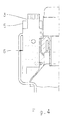
- Fig. 4 shows in section IV-IV the oil module as it is carried out according to Fig. 3.
- the oil filter 3 is interchangeable and is inserted into the molded part on the housing 6.
- the ventilation system 5 with oil separator is also directly on the housing 6 formed.
- a pre-separation of oil in a calming space 13 be made.
- the calming space 13 is connected upstream of the oil module 1.
- the Oil mist-air mixture passes from a crank chamber 18 and an inlet opening 12 first in the calming room 13 and from there larger after separation Oil droplets over the cross section 14 into the oil module 1.
- the ventilation system 5 with oil separator can be used for the separation according to this design smaller oil droplets can be optimized.
Landscapes
- Engineering & Computer Science (AREA)
- Mechanical Engineering (AREA)
- General Engineering & Computer Science (AREA)
- Lubrication Details And Ventilation Of Internal Combustion Engines (AREA)
Description
Ausführungsbeispiele der Erfindung sind an Hand von Zeichnungen dargestellt.
Es zeigt:
- Fig. 1
- eine Seitenansicht des Ölmoduls
- Fig. 2
- einen Schnitt II-II durch Ölmodul und angrenzendes Kurbelgehäuse
- Fig. 3
- eine Seitenansicht des Ölmoduls, bei dem Ölfilter und Entlüftungssystem mit Ölabscheider integraler Bestandteil des Gehäuses sind
- Fig. 4
- einen Schnitt V-V durch Ölmodul und Kurbelgehäuse
- Fig. 5
- ein Ölmodul mit vorgeschaltetem Beruhigungsraum
Claims (4)
- Ölmodul für Brennkraftmaschinen, dadurch gekennzeichnet, daß das Ölmodul (1) als eine bauliche Einheit aus Ölfilter (3), Ölkühler (4) und Entlüftungssystem (5) mit Ölabscheider ausgebildet ist und daß das Ölmodul (1) als Ganzes an die Brennkraftmaschine angeflanscht ist.
- Ölmodul nach Anspruch 1, dadurch gekennzeichnet, daß das Ölmodul (1) aus einem Gehäuse (6) gebildet wird, welches den Ölkühler (4) vollständig umschließt, daß das Gehäuse (6) an einem Ende einen Kühlwasser- und Öleintritt (7, 8) und am anderen Ende einen Kühlwasseraustritt (9) und Ölübertritt (10) zu dem an das Gehäuse (6) angebauten Ölfilter (3) aufweist. daß vom Ölfilter (3) ein ins Gehäuse (6) integrierter Ölkanal (11) zu den Schmierstellen führt, daß die dem Kurbelgehäuse (2) zugewandte Seitenfläche des Gehäuses (6) einen im Gehäuse (6) integrierten Übertrittsquerschnitt (14) besitzt, welcher mit dem Kurbelgehäuse (2) kommuniziert, und daß dieser Übertrittsquerschnitt (14) in ein an das Gehäuse (6) angeschlossenes Entlüftungssystem (5) mit Ölabscheider mündet, welches seinerseits einen Luftkanal (15) und einen Ölrücklaufkanal (16) aufweist, der in eine Ölwanne (17) mündet.
- Ölmodul nach den Ansprüchen 1 und 2, dadurch gekennzeichnet, daß das Ölmodul (1) aus einem Gehäuse (6) gebildet wird, welches den Ölkühler (4) vollständig umschließt und ein Bauteil für den Ölfilter (3) und das Entlüftungssystem (5) mit Ölabscheider an das Gehäuse (6) angeformt ist, wobei der Ölfilter (3) einen auswechselbaren Filtereinsatz aufweist.
- Ölmodul nach den Ansprüchen 1 und 2, dadurch gekennzeichnet, daß dem Ölmodul (1) ein Beruhigungsraum (13) vorgeschaltet ist, derart, daß der Beruhigungsraum (13) eine Eintrittsöffnung (12) zum Kurbelraum (18) hin aufweist und über den Übertrittsquerschnitt (14) mit dem Ölmodul (1) kommuniziert.
Applications Claiming Priority (2)
| Application Number | Priority Date | Filing Date | Title |
|---|---|---|---|
| DE19736039.4A DE19736039B4 (de) | 1997-08-20 | 1997-08-20 | Brennkraftmaschine mit einem Ölmodul |
| DE19736039 | 1997-08-20 |
Publications (2)
| Publication Number | Publication Date |
|---|---|
| EP0898060A1 EP0898060A1 (de) | 1999-02-24 |
| EP0898060B1 true EP0898060B1 (de) | 2002-06-05 |
Family
ID=7839498
Family Applications (1)
| Application Number | Title | Priority Date | Filing Date |
|---|---|---|---|
| EP98114489A Revoked EP0898060B1 (de) | 1997-08-20 | 1998-08-01 | Ölmodul für Brennkraftmaschinen |
Country Status (2)
| Country | Link |
|---|---|
| EP (1) | EP0898060B1 (de) |
| DE (2) | DE19736039B4 (de) |
Cited By (2)
| Publication number | Priority date | Publication date | Assignee | Title |
|---|---|---|---|---|
| EP1498582A2 (de) | 2003-07-14 | 2005-01-19 | Hengst GmbH & Co. KG | Ölfilter und Ölabscheider-Modul für eine Brennkraftmaschine |
| DE202004018136U1 (de) * | 2004-07-14 | 2005-11-24 | Daimlerchrysler Ag | Öl-Kühlmittel-Modul |
Families Citing this family (6)
| Publication number | Priority date | Publication date | Assignee | Title |
|---|---|---|---|---|
| JP3423649B2 (ja) * | 1999-09-03 | 2003-07-07 | 本田技研工業株式会社 | 内燃機関のブリーザ室構造 |
| DE20012736U1 (de) | 2000-07-22 | 2000-09-21 | Filterwerk Mann + Hummel GmbH, 71638 Ludwigsburg | Baugruppe für eine Brennkraftmaschine mit einem Ölfilter |
| JP4162020B2 (ja) | 2006-07-18 | 2008-10-08 | トヨタ自動車株式会社 | ブローバイガス還元装置のオイル回収構造 |
| DE102011115410A1 (de) | 2011-10-08 | 2013-04-11 | Daimler Ag | Anordnung eines Ölmoduls und einer Ölpumpe an einer Verbrennungskraftmaschine |
| JP6678543B2 (ja) | 2016-09-02 | 2020-04-08 | 株式会社クボタ | ブローバイガス昇温装置 |
| FR3087496B1 (fr) * | 2018-10-22 | 2021-01-29 | Renault Sas | Systeme de motorisation de vehicule a faible encombrement |
Family Cites Families (16)
| Publication number | Priority date | Publication date | Assignee | Title |
|---|---|---|---|---|
| US2068395A (en) * | 1932-07-21 | 1937-01-19 | Michiana Products Corp | Filter and heat exchanger |
| US3353590A (en) * | 1965-07-12 | 1967-11-21 | Holman And Moody Inc | Unitary oil filtering and cooling attachment for internal combustion engines |
| DE1992788U (de) * | 1968-06-07 | 1968-08-29 | Rheinstahl Hanomag Ag | Brennkraftmaschine. |
| US4324213A (en) * | 1980-01-21 | 1982-04-13 | Cummins Engine Company, Inc. | Lubrication fluid filtering and cooling assembly |
| US4426965A (en) * | 1982-02-11 | 1984-01-24 | Cummins Engine Company, Inc. | Unitized oil cooler and filter assembly |
| DE4240464A1 (de) * | 1992-12-02 | 1994-06-09 | Opel Adam Ag | Zylinderkurbelgehäuse für eine Brennkraftmaschine mit darin angeordneten Be- und Entlüftungskanälen |
| DE4313506A1 (de) * | 1993-04-24 | 1994-10-27 | Knecht Filterwerke Gmbh | Ölkühler in Scheibenbauweise |
| FR2708038A1 (fr) * | 1993-07-23 | 1995-01-27 | Peugeot | Ensemble pour circuit de lubrification d'un moteur à combustion interne de véhicule automobile. |
| US5406910A (en) * | 1993-11-22 | 1995-04-18 | Ford Motor Company | Combination oil cooler and oil filter assembly for internal combustion engine |
| DE4400952C1 (de) * | 1994-01-14 | 1995-05-24 | Daimler Benz Ag | Gehäusedeckel für eine Brennkraftmaschine |
| DE4400953C2 (de) * | 1994-01-14 | 1997-06-05 | Daimler Benz Ag | Schmierölvorrichtung für eine Brennkraftmaschine |
| GB2294091B (en) * | 1994-10-14 | 1999-05-26 | Perkins Ltd | An assembly of auxiliary apparatus for an internal combustion engine |
| DE4442148A1 (de) * | 1994-11-26 | 1996-05-30 | Knecht Filterwerke Gmbh | Ölfilter |
| GB2298037B (en) * | 1995-02-18 | 1999-07-28 | Glacier Metal Co Ltd | Temperature regulating liquid conditioning arrangements |
| DE19606182A1 (de) * | 1996-02-20 | 1997-08-21 | Mann & Hummel Filter | Abtrennvorrichtung |
| DE19650033A1 (de) * | 1996-12-03 | 1998-06-04 | Mann & Hummel Filter | Baugruppe für eine Verbrennungskraftmaschine |
-
1997
- 1997-08-20 DE DE19736039.4A patent/DE19736039B4/de not_active Expired - Lifetime
-
1998
- 1998-08-01 EP EP98114489A patent/EP0898060B1/de not_active Revoked
- 1998-08-01 DE DE59804293T patent/DE59804293D1/de not_active Expired - Lifetime
Cited By (4)
| Publication number | Priority date | Publication date | Assignee | Title |
|---|---|---|---|---|
| EP1498582A2 (de) | 2003-07-14 | 2005-01-19 | Hengst GmbH & Co. KG | Ölfilter und Ölabscheider-Modul für eine Brennkraftmaschine |
| EP2383443A1 (de) | 2003-07-14 | 2011-11-02 | Hengst GmbH & Co. KG | Modul für eine Brennkraftmaschine |
| DE202004018136U1 (de) * | 2004-07-14 | 2005-11-24 | Daimlerchrysler Ag | Öl-Kühlmittel-Modul |
| WO2006005329A1 (de) | 2004-07-14 | 2006-01-19 | Hengst Gmbh & Co. Kg | Öl-kühlmittel-modul mit kühllmittelpflegesystem |
Also Published As
| Publication number | Publication date |
|---|---|
| DE59804293D1 (de) | 2002-07-11 |
| EP0898060A1 (de) | 1999-02-24 |
| DE19736039B4 (de) | 2018-01-11 |
| DE19736039A1 (de) | 1999-02-25 |
Similar Documents
| Publication | Publication Date | Title |
|---|---|---|
| EP1751405B1 (de) | Ölwannenanordnung | |
| EP1360400B1 (de) | Ölauffangvorrichtung für eine brennkraftmaschine | |
| EP0187263A1 (de) | Gehäuse für Hubkolben-Brennkraftmaschinen | |
| EP0925428B1 (de) | Baugruppe für eine verbrennungskraftmaschine | |
| DE10029844B4 (de) | Brennkraftmaschine, insbesondere für Motorräder | |
| DE3923986C1 (de) | ||
| WO2006000268A1 (de) | Brennkraftmaschine mit druckumlaufschmierung nach dem trockensumpfprinzip | |
| WO2006000269A1 (de) | Brennkraftmaschine mit druckumlaufschmierung nach dem trockensumpfprinzip | |
| EP0898060B1 (de) | Ölmodul für Brennkraftmaschinen | |
| DE102013206419B4 (de) | Motorbaugruppe mit an einem Motorblock montiertem Luft-Öl-Abscheider | |
| EP0732484B1 (de) | Entlüftungsvorrichtung für das Kurbelgehäuse einer Brennkraftmaschine | |
| DE112006000098T5 (de) | Motorblockstruktur | |
| DE10159104B4 (de) | Brennkraftmaschine | |
| DE10159090C2 (de) | Ölauffangvorrichtung und Ölpumpe für eine Brennkraftmaschine | |
| EP1599659B1 (de) | Vorrichtung zur entschäumung von öl im schmiermittelkreislauf einer brennkraftmaschine | |
| EP1310637A2 (de) | Brennkraftmaschine mit mindestens zwei Zylinderbankreihen | |
| EP1498582B1 (de) | Ölfilter und Ölabscheider-Modul für eine Brennkraftmaschine | |
| DE10119924B4 (de) | Brennkraftmaschine mit Druckumlaufschmierung | |
| DE3918785A1 (de) | Sauganlage einer brennkraftmaschine | |
| DE102008014828A1 (de) | Brennkraftmaschine | |
| DE19736040B4 (de) | Vorrichtung zur Abscheidung von Öl aus einem Öl-Gasgemisch von Brennkraftmaschinen | |
| DE102008009873A1 (de) | Schmiermittelführungsgehäuse | |
| DE10036130A1 (de) | Zylinderkurbelgehäuse einer Brennkraftmaschine | |
| DE102004013763A1 (de) | Brennkraftmaschine mit Entlüftungssystem | |
| DE102007014546A1 (de) | Kurbelgehäuse |
Legal Events
| Date | Code | Title | Description |
|---|---|---|---|
| PUAI | Public reference made under article 153(3) epc to a published international application that has entered the european phase |
Free format text: ORIGINAL CODE: 0009012 |
|
| AK | Designated contracting states |
Kind code of ref document: A1 Designated state(s): DE FR GB IT NL SE |
|
| AX | Request for extension of the european patent |
Free format text: AL;LT;LV;MK;RO;SI |
|
| RTI1 | Title (correction) | ||
| 17P | Request for examination filed |
Effective date: 19990306 |
|
| AKX | Designation fees paid |
Free format text: DE FR GB IT NL SE |
|
| GRAG | Despatch of communication of intention to grant |
Free format text: ORIGINAL CODE: EPIDOS AGRA |
|
| GRAG | Despatch of communication of intention to grant |
Free format text: ORIGINAL CODE: EPIDOS AGRA |
|
| GRAH | Despatch of communication of intention to grant a patent |
Free format text: ORIGINAL CODE: EPIDOS IGRA |
|
| 17Q | First examination report despatched |
Effective date: 20011031 |
|
| GRAH | Despatch of communication of intention to grant a patent |
Free format text: ORIGINAL CODE: EPIDOS IGRA |
|
| GRAA | (expected) grant |
Free format text: ORIGINAL CODE: 0009210 |
|
| AK | Designated contracting states |
Kind code of ref document: B1 Designated state(s): DE FR GB IT NL SE |
|
| REG | Reference to a national code |
Ref country code: GB Ref legal event code: FG4D Free format text: NOT ENGLISH |
|
| REF | Corresponds to: |
Ref document number: 59804293 Country of ref document: DE Date of ref document: 20020711 |
|
| ET | Fr: translation filed | ||
| PLBQ | Unpublished change to opponent data |
Free format text: ORIGINAL CODE: EPIDOS OPPO |
|
| PLBI | Opposition filed |
Free format text: ORIGINAL CODE: 0009260 |
|
| PLBF | Reply of patent proprietor to notice(s) of opposition |
Free format text: ORIGINAL CODE: EPIDOS OBSO |
|
| 26 | Opposition filed |
Opponent name: HENGST GMBH & CO. KG Effective date: 20030305 |
|
| NLR1 | Nl: opposition has been filed with the epo |
Opponent name: HENGST GMBH & CO. KG |
|
| PLAX | Notice of opposition and request to file observation + time limit sent |
Free format text: ORIGINAL CODE: EPIDOSNOBS2 |
|
| PLBB | Reply of patent proprietor to notice(s) of opposition received |
Free format text: ORIGINAL CODE: EPIDOSNOBS3 |
|
| PLAY | Examination report in opposition despatched + time limit |
Free format text: ORIGINAL CODE: EPIDOSNORE2 |
|
| PLAT | Information related to reply to examination report in opposition deleted |
Free format text: ORIGINAL CODE: EPIDOSDORE3 |
|
| PLBC | Reply to examination report in opposition received |
Free format text: ORIGINAL CODE: EPIDOSNORE3 |
|
| PLBC | Reply to examination report in opposition received |
Free format text: ORIGINAL CODE: EPIDOSNORE3 |
|
| PLAY | Examination report in opposition despatched + time limit |
Free format text: ORIGINAL CODE: EPIDOSNORE2 |
|
| PLAH | Information related to despatch of examination report in opposition + time limit modified |
Free format text: ORIGINAL CODE: EPIDOSCORE2 |
|
| PLBC | Reply to examination report in opposition received |
Free format text: ORIGINAL CODE: EPIDOSNORE3 |
|
| RDAF | Communication despatched that patent is revoked |
Free format text: ORIGINAL CODE: EPIDOSNREV1 |
|
| REG | Reference to a national code |
Ref country code: NL Ref legal event code: TD Effective date: 20110304 |
|
| REG | Reference to a national code |
Ref country code: FR Ref legal event code: CD |
|
| APBM | Appeal reference recorded |
Free format text: ORIGINAL CODE: EPIDOSNREFNO |
|
| APBP | Date of receipt of notice of appeal recorded |
Free format text: ORIGINAL CODE: EPIDOSNNOA2O |
|
| APAH | Appeal reference modified |
Free format text: ORIGINAL CODE: EPIDOSCREFNO |
|
| REG | Reference to a national code |
Ref country code: DE Ref legal event code: R081 Ref document number: 59804293 Country of ref document: DE Owner name: MAN TRUCK & BUS AG, DE Free format text: FORMER OWNER: MAN NUTZFAHRZEUGE AG, 80995 MUENCHEN, DE Effective date: 20110406 |
|
| APBQ | Date of receipt of statement of grounds of appeal recorded |
Free format text: ORIGINAL CODE: EPIDOSNNOA3O |
|
| REG | Reference to a national code |
Ref country code: FR Ref legal event code: PLFP Year of fee payment: 18 |
|
| PGFP | Annual fee paid to national office [announced via postgrant information from national office to epo] |
Ref country code: GB Payment date: 20150901 Year of fee payment: 18 |
|
| PGFP | Annual fee paid to national office [announced via postgrant information from national office to epo] |
Ref country code: SE Payment date: 20150825 Year of fee payment: 18 Ref country code: FR Payment date: 20150630 Year of fee payment: 18 |
|
| REG | Reference to a national code |
Ref country code: DE Ref legal event code: R103 Ref document number: 59804293 Country of ref document: DE Ref country code: DE Ref legal event code: R064 Ref document number: 59804293 Country of ref document: DE |
|
| APBU | Appeal procedure closed |
Free format text: ORIGINAL CODE: EPIDOSNNOA9O |
|
| PGFP | Annual fee paid to national office [announced via postgrant information from national office to epo] |
Ref country code: DE Payment date: 20151029 Year of fee payment: 18 |
|
| RDAG | Patent revoked |
Free format text: ORIGINAL CODE: 0009271 |
|
| STAA | Information on the status of an ep patent application or granted ep patent |
Free format text: STATUS: PATENT REVOKED |
|
| 27W | Patent revoked |
Effective date: 20160119 |
|
| GBPR | Gb: patent revoked under art. 102 of the ep convention designating the uk as contracting state |
Effective date: 20160119 |
|
| PGFP | Annual fee paid to national office [announced via postgrant information from national office to epo] |
Ref country code: NL Payment date: 20160824 Year of fee payment: 19 |
|
| PGFP | Annual fee paid to national office [announced via postgrant information from national office to epo] |
Ref country code: IT Payment date: 20160822 Year of fee payment: 19 |
|
| REG | Reference to a national code |
Ref country code: SE Ref legal event code: ECNC |