EP0897826B1 - Catenary wire stringing device - Google Patents
Catenary wire stringing device Download PDFInfo
- Publication number
- EP0897826B1 EP0897826B1 EP98890205.2A EP98890205A EP0897826B1 EP 0897826 B1 EP0897826 B1 EP 0897826B1 EP 98890205 A EP98890205 A EP 98890205A EP 0897826 B1 EP0897826 B1 EP 0897826B1
- Authority
- EP
- European Patent Office
- Prior art keywords
- transverse
- machine
- guide
- transverse guide
- machine according
- Prior art date
- Legal status (The legal status is an assumption and is not a legal conclusion. Google has not performed a legal analysis and makes no representation as to the accuracy of the status listed.)
- Expired - Lifetime
Links
Images

Classifications
-
- B—PERFORMING OPERATIONS; TRANSPORTING
- B60—VEHICLES IN GENERAL
- B60M—POWER SUPPLY LINES, AND DEVICES ALONG RAILS, FOR ELECTRICALLY- PROPELLED VEHICLES
- B60M1/00—Power supply lines for contact with collector on vehicle
- B60M1/12—Trolley lines; Accessories therefor
- B60M1/28—Manufacturing or repairing trolley lines
Definitions
- the invention relates to a machine for laying a contact wire and / or a supporting cable of a catenary of a track, with a supported on rail chassis machine frame on which a - wound catenary or carrying rope containing - wire drum and a guide means arranged with a at an upper end of a support pole are mounted on a drive height adjustable guide roller for guiding the unwound from the wire drum contact wire or support cable, wherein the guide means is pivotally mounted by means of a pivot drive about an axis extending in the machine longitudinal axis.
- the guide device has the form of a height-adjustable Jib crane, which is mounted rotatably about a vertical axis on the machine frame and at the free end of the two guide rollers for guiding the contact wire or supporting cable are arranged.
- the fork-like support of each guide roller is movably connected to a support arm to allow an individual rotation of the guide rollers about an axis extending approximately in the longitudinal direction of the track in the course of the required lateral pivoting of the crane.
- the guide device consists of a roller device over which the wire is guided and which is arranged transversely adjustable by means of a spindle drive on a height-adjustable support frame.
- the support frame in turn is mounted on a work platform, which is connected in height adjustable with the rail vehicle.
- Another, according to AT-B-398 737 known machine is equipped with two wire drums for carrying cable and trolley wire, each of which is assigned its own, independent guide device.
- the latter take the form of height-adjustable cantilever arms, which are mounted on the machine frame so that they can be swiveled sideways, and at the free end each have a device for guiding and clamping the wire.
- the DE-A-20 12 248 Finally, describes a machine for the overhead line assembly with a guide device, which each includes a guide roller for contact wire and suspension cable. These two superposed guide rollers are formed telescopically adjustable by means of a device mounted on the machine frame both in the vertical and in the horizontal direction.
- the object of the present invention is now to provide a machine of the generic type, with an unhindered, accurate laying of the catenary is possible under a variety of conditions.
- This inventive design of the guide device advantageously allows a further transverse adjustment of the guide roller in addition to the running on the basis of the pivot drive maximum Querverschwenkung.
- the adjustment range of the guide device in the transverse direction of the track is increased and thus favors an even more accurate positioning of the contact wire.
- the relative displacement between the guide roller and the support pole but in the laying of the support cable the continuous guide in track longitudinal direction can be problematic due to its location above the boom. Due to the construction of the invention, it is now possible to easily bypass the boom to avoid collision with the support mast and still position the suspension rope by transverse displacement of the guide role exactly in the height and in particular transverse position required for the assembly or to hold there.
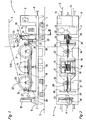
- Fig. 1 and 2 is a machine 1 for laying a contact wire 2 or a supporting cable 3 of a catenary 4 of a track 5 shown.
- the machine 1 has a machine frame 6, which is supported on the track 5 via two rail carriages 7 and is equipped at the end with a coupling 8 for integration into a train and with a driving or working cab 9 and a crane 10 which can be tilted vertically and laterally ,
- a motor 11 and a hydraulic unit 12 are provided for the power supply of a traction drive 13 of the machine 1 and all other, still to be described drives, which are remotely controllable by means of control devices 14.
- the contact wire 2 to be laid or the carrying cable 3 is wound on a wire drum 15, which is rotatably mounted on a carriage 17 about a horizontal axis of rotation 16 extending in the cross-machine direction. This is in turn mounted on a pivot frame 18 and displaceable relative to this by means of drives 19 in the cross-machine direction.
- a tensioning device 20 is provided on the pivoting frame 18, which is formed from two deflection rollers 21 which are distanced from the wire drum 15 in the machine longitudinal direction. These are rotatable about axes 22 parallel to the axis of rotation 16 and equipped with a brake disk 23 and a braking device 24 acting on them.
- the deflection rollers 21 can each be acted upon by a hydraulic motor 25.
- the swing frame 18 is connected in the region between the car 9 and the crane 10 with the machine frame 6 via two supports 26 and mounted on this pivotable about a machine axis in the horizontal axis 27.
- the axis 27 is formed by a shaft 28 on the supports 26 is mounted and on which the swing frame 18 is mounted pendulum in the manner of a cradle.
- One of the two shafts 28 protrudes on one side over the support 26 in the machine longitudinal direction and serves to support a guide device 29 for the contact wire 2 or the supporting cable 3 connected to the shaft 28 - and via this to the pivoting frame 18 - for pivoting the guide means 29 together with the associated pivot frame 18 about the axis 27, a pivot drive 30 is provided which is articulated on the pivot frame 18 and fixed to the machine frame 6.
- the guide means 29 consists essentially of a telescopically height adjustable by a drive 33 support pole 31 and arranged at its upper end guide rollers 32 for guiding the unwound from the wire drum contact wire 2 and 3.
- the total of four guide rollers 32 are in an array of two in Machine longitudinal direction successively positioned pairs of two coaxial rollers mounted on a roller block 34 and freely rotatable about cross-machine direction aligned axes 35, wherein the one axis 35 to the second axis 35 is slightly offset in the vertical direction.
- the roller block 34 is in turn connected by means of a transverse displacement device 36 with the support mast 31 and relative to this by means of a Querverstellantriebes 37 and 47 in a direction normal to the longitudinal direction of the support mast 31 and transverse to the machine longitudinal axis extending direction adjustable.
- the transverse displacement device 36 is composed of a first and below this arranged, second transverse guide 38,39 together, each having two spaced apart in the machine longitudinal direction, extending in the cross-machine direction transverse guide columns 40 and 41 respectively.
- On these two sliding bushes 42,43 are mounted transversely.
- the total of four bushings 42 of the upper, first transverse guide 38 are connected to a horizontal support plate 44, on which the roller block 34 is mounted with the guide rollers 32, while the sliding bushes 43 of the lower, second transverse guide 39 are mounted on a support plate 45 which in turn at the top the support pole 31 is attached.
- transverse guide columns 40 of the first transverse guide 38 are spaced apart in the vertical direction from the transverse guide columns 41 of the second transverse guide 39, wherein the spaced apart in the cross-machine direction ends of the four transverse guide columns 40 and 41 each mounted on a common, vertically arranged plate 46 and so - constructive unit - are fixed in position relative to each other.
- Each of the two transverse guides 38 and 39 is associated with its own Querverstellantrieb 37 and 47, which is in each case designed as a rotatable spindle 49 by means of a hydraulic motor 48.
- This runs in each case parallel to the transverse guide columns 40,41 and is arranged between these and rotatably mounted on the vertical plates 46 in each case a shaft bearing 50.
- the two Hydrornotoren 48 are also mounted on one of the platens 46 and communicate with the respectively associated spindle 49 and with a rotatably arranged on this drive pinion 51 via a drive chain 52 in connection.
- Each spindle 49 is provided with a spindle nut 53, one of which is fixedly connected to the support plate 44 of the roller block 34 and the other with the lower support plate 45.
- a contact wire side holder 57 fastened to it constitutes an obstacle to the support mast 31.
- the roller block 34 is moved with the guide rollers 32 based on the transverse displacement device 36 in the direction opposite to the pivoting direction.
- the Querverstellantriebe 37 and / or 47 acted to either adjust only the roller block 34 on the first transverse guide 38 or the entire, formed from first and second transverse guide 38.39 unit relative to the support mast 31 in Machine cross direction to move until the support cable 3 can be performed in the gewünsch th situation.
- the transverse displacement device 36 When installing the (lower) contact wire 2, the use of the transverse displacement device 36 is normally not required, but it is to produce the prescribed zig-zag course of the contact wire 2, only the swing frame 18 together with the support mast 31 by means of the pivot drive 30 about the axis 27th swung back and forth.
Landscapes
- Engineering & Computer Science (AREA)
- Manufacturing & Machinery (AREA)
- Mechanical Engineering (AREA)
- Carriers, Traveling Bodies, And Overhead Traveling Cranes (AREA)
- Jib Cranes (AREA)
- Electric Cable Installation (AREA)
- Forklifts And Lifting Vehicles (AREA)
- Lift-Guide Devices, And Elevator Ropes And Cables (AREA)
Description
Die Erfindung betrifft eine Maschine zum Verlegen eines Fahrdrahtes und/oder eines Tragseiles einer Oberleitung eines Gleises, mit einem auf Schienenfahrwerken abgestützten Maschinenrahmen, auf dem eine - aufgewickelten Fahrdraht bzw. Tragseil beinhaltende - Drahttrommel und eine Führungseinrichtung mit einer an einem oberen Ende eines Tragmastes angeordneten, über einen Antrieb höhenverstellbaren Führungsrolle zur Führung des von der Drahttrommel abgewickelten Fahrdrahtes bzw. Tragseiles gelagert sind, wobei die Führungseinrichtung anhand eines Schwenkantriebes um eine in Maschinenlängsrichtung verlaufende Achse verschwenkbar gelagert ist.The invention relates to a machine for laying a contact wire and / or a supporting cable of a catenary of a track, with a supported on rail chassis machine frame on which a - wound catenary or carrying rope containing - wire drum and a guide means arranged with a at an upper end of a support pole are mounted on a drive height adjustable guide roller for guiding the unwound from the wire drum contact wire or support cable, wherein the guide means is pivotally mounted by means of a pivot drive about an axis extending in the machine longitudinal axis.
Aus der
Eine weitere Maschine zur Oberleitungsinstallation ist in der
Gemäß
Eine andere, gemäß AT-B-398 737 bekannte Maschine ist mit zwei Drahttrommeln für Tragseil und Fahrdraht ausgestattet, denen jeweils eine eigene, unabhängige Führungseinrichtung zugeordnet ist. Letztere haben die Form von höhenverstellbaren Auslegerarmen, die seitenverschwenkbar auf dem Maschinenrahmen montiert sind und am freien Ende jeweils eine Vorrichtung zum Führen und Festklemmen des Drahtes aufweisen.Another, according to AT-B-398 737 known machine is equipped with two wire drums for carrying cable and trolley wire, each of which is assigned its own, independent guide device. The latter take the form of height-adjustable cantilever arms, which are mounted on the machine frame so that they can be swiveled sideways, and at the free end each have a device for guiding and clamping the wire.
Die
Die Aufgabe der vorliegenden Erfindung besteht nun in der Schaffung einer Maschine der gattungsgemäßen Art, mit der unter verschiedensten Einsatzbedingungen ein ungehindertes, genaues Verlegen der Fahrleitung möglich ist.The object of the present invention is now to provide a machine of the generic type, with an unhindered, accurate laying of the catenary is possible under a variety of conditions.
Gemäß der Erfindung wird diese Aufgabe mit der eingangs beschriebenen Maschine durch die im Kennzeichen von Anspruch 1 angeführten Merkmale gelöst.According to the invention, this object is achieved with the machine described above by the features cited in the characterizing part of
Diese erfindungsgemäße Ausbildung der Führungseinrichtung ermöglicht in vorteilhafter Weise eine weitere Querverstellung der Führungsrolle zusätzlich zur anhand des Schwenkantriebes ausgeführten maximalen Querverschwenkung. Dadurch wird der Verstellbereich der Führungseinrichtung in Gleisquerrichtung vergrößert und so eine noch genauere Positionierung des Fahrdrahtes begünstigt. Von besonderem Vorteil ist die Relativverstellung zwischen Führungsrolle und Tragmast aber bei der Verlegung des Tragseiles, dessen kontinuierliche Führung in Gleislängsrichtung sich aufgrund seiner Lage oberhalb des Auslegerarmes problematisch gestalten kann. Durch die erfindungsgemäße Ausbildung ist es nun möglich, mit dem Tragmast den Ausleger zur Vermeidung eines Zusammenstoßens ganz einfach zu umgehen und das Tragseil trotzdem durch Querverschiebung der Führungsrolle genau in der für die Montage erforderlichen Höhen- und insbesondere Querlage zu positionieren bzw. dort zu halten.This inventive design of the guide device advantageously allows a further transverse adjustment of the guide roller in addition to the running on the basis of the pivot drive maximum Querverschwenkung. As a result, the adjustment range of the guide device in the transverse direction of the track is increased and thus favors an even more accurate positioning of the contact wire. Of particular advantage is the relative displacement between the guide roller and the support pole but in the laying of the support cable, the continuous guide in track longitudinal direction can be problematic due to its location above the boom. Due to the construction of the invention, it is now possible to easily bypass the boom to avoid collision with the support mast and still position the suspension rope by transverse displacement of the guide role exactly in the height and in particular transverse position required for the assembly or to hold there.
Weitere Vorteile ergeben sich aus den Unteransprüchen sowie aus den Zeichnungen.Further advantages will be apparent from the subclaims and from the drawings.
Die Erfindung wird im folgenden anhand eines in den Zeichnungen dargestellten Ausführungsbeispieles näher erläutert.The invention will be explained in more detail below with reference to an embodiment shown in the drawings.
Es zeigen:
-
Fig. 1 und 2 eine Seitenansicht bzw. eine Draufsicht auf eine Maschine zum Verlegen einer Oberleitung eines Gleises, -
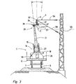
Fig. 3 eine vereinfachte Ansicht in Maschinenlängsrichtung gemäß der Schnittlinie III inFig. 1 , -
Fig. 4 und 5 je eine Seitenansicht der erfindungsgemäß ausgebildeten Führungseinrichtung in Maschinenlängsrichtung bzw. -querrichtung, und -
Fig. 6 eine Ansicht gemäß Schnittlinie VI inFig. 4 .
-
Fig. 1 and 2 a side view and a top view of a machine for laying a catenary of a track, -
Fig. 3 a simplified view in the machine longitudinal direction according to the section line III inFig. 1 . -
4 and 5 depending on a side view of the inventively designed guide device in the machine longitudinal direction or transverse direction, and -
Fig. 6 a view according to section line VI inFig. 4 ,
In
Der zu verlegende Fahrdraht 2 bzw. das Tragseil 3 ist auf einer Drahttrommel 15 aufgewickelt, die um eine in Maschinenquerrichtung verlaufende, horizontale Rotationsachse 16 drehbar auf einem Schlitten 17 montiert ist. Dieser ist seinerseits auf einem Schwenkrahmen 18 gelagert und relativ zu diesem anhand von Antrieben 19 in Maschinenquerrichtung verschiebbar. Neben der Drahttrommel 15 ist auf dem Schwenkrahmen 18 eine Zugspannungsvorrichtung 20 vorgesehen, die aus zwei von der Drahttrommel 15 in Maschinenlängsrichtung distanzierten Umlenkrollen 21 gebildet ist. Diese sind um zur Rotationsachse 16 parallele Achsen 22 rotierbar und mit einer Bremsscheibe 23 und einer auf diese wirkenden Bremsvorrichtung 24 ausgestattet. Zur Aufrechterhaltung einer konstanten Zugspannung sind die Umlenkrollen 21 jeweils durch einen Hydromotor 25 beaufschlagbar.The
Wie im folgenden auch anhand der
Die Führungseinrichtung 29 besteht im wesentlichen aus einem anhand eines Antriebes 33 teleskopisch höhenverstellbaren Tragmast 31 und an dessen oberem Ende angeordneten Führungsrollen 32 zur Führung des von der Drahttrommel abgewickelten Fahrdrahtes 2 bzw. Tragseiles 3. Die insgesamt vier Führungsrollen 32 sind in einer Anordnung von zwei in Maschinenlängsrichtung hintereinander positionierten Paaren von jeweils zwei koaxial angeordneten Rollen auf einem Rollenbock 34 befestigt und um in Maschinenquerrichtung ausgerichtete Achsen 35 frei rotierbar, wobei die eine Achse 35 zur zweiten Achse 35 in vertikaler Richtung geringfügig versetzt ist. Der Rollenbock 34 ist seinerseits anhand einer Querverschiebevorrichtung 36 mit dem Tragmast 31 verbunden und relativ zu diesem mittels eines Querverstellantriebes 37 bzw. 47 in einer normal zur Längsrichtung des Tragmastes 31 und quer zur Maschinenlängsachse verlaufenden Richtung verstellbar ausgebildet.The guide means 29 consists essentially of a telescopically height adjustable by a
Wie nun aus den
Jeder der beiden Querführungen 38 und 39 ist ein eigener Querverstellantrieb 37 bzw. 47 zugeordnet, der jeweils als mittels eines Hydromotors 48 rotierbare Spindel 49 ausgebildet ist. Diese verläuft jeweils parallel zu den Querführungssäulen 40,41 und ist zwischen diesen angeordnet sowie auf den vertikalen Platten 46 in je einem Wellenlager 50 drehbar montiert. Die beiden Hydrornotoren 48 sind ebenfalls auf einer der Ptatten 46 befestigt und stehen mit der jeweils zugeordneten Spindel 49 bzw. mit einem auf dieser drehfest angeordneten Antriebsritzel 51 über eine Antriebskette 52 in Verbindung. Jede Spindel 49 ist mit einer Spindelmutter 53 versehen, von welchen die eine mit der Tragplatte 44 des Rollenbocks 34 und die andere mit der unteren Tragplatte 45 fix verbunden ist. Eine Beaufschlagung des Querverstellantriebes 37 bewirkt somit eine Querverstellung lediglich des Rollenbocks 34 auf den Querführungssäulen 40 der ersten Querführung 38 (siehe strichpunktiert gezeigte Stellung in
Im - in
Soll beispielsweise ein Tragseil 3 auf einem Auslegerrohr 56 montiert werden, so stellt dabei ein an diesem befestigter Fahrdraht-Seitenhalter 57 ein Hindernis für den Tragmast 31 dar. Um dieses zu umgehen, wird der Schwenkrahmen 18 zusammen mit dem drehfest damit verbundenen, die Führungseinrichtung 29 lagernden Tragmast 31 anhand des Schwenkantriebes 30 um die Achse 27 so weit wie erforderlich seitlich ausgeschwenkt. Zur gewünschten Rückpositionierung des Tragseiles 3 in Gleismitte wird nun der Rollenbock 34 mit den Führungsrollen 32 anhand der Querverschiebevorrichtung 36 in der der Verschwenkrichtung entgegengesetzten Richtung verschoben. Zu diesem Zweck werden, je nach Notwendigkeit, die Querverstellantriebe 37 und/oder 47 beaufschlagt, um entweder nur den Rollenbock 34 auf der ersten Querführung 38 zu verstellen oder die gesamte, aus erster und zweiter Querführung 38,39 gebildete Einheit gegenüber dem Tragmast 31 in Maschinenquerichtung zu verschieben, bis das Tragseil 3 in der gewünsch ten Lage geführt werden kann.If, for example, a carrying
Beim Installieren des (tiefer gelegenen) Fahrdrahtes 2 ist der Einsatz der Querverschiebevorrichtung 36 normalerweise nicht erforderlich, sondern es wird zur Herstellung des vorgeschriebenen Zick-Zack-Verlaufes des Fahrdrahtes 2 lediglich der Schwenkrahmen 18 mitsamt dem Tragmast 31 anhand des Schwenkantriebes 30 um die Achse 27 hin- und hergeschwenkt.When installing the (lower)
Claims (9)
- A machine for installing a contact wire (2) and/or a carrying cable (3) of an overhead line (4) of a track (5), including a machine frame (6) which is supported on on-track undercarriages (7) and on which are mounted a wire drum (15) - containing rolled-up contact wire (2) or carrying cable (3) - and a guiding device (29) having a guide roller (32), vertically adjustable by means of a drive (33) and arranged at an upper end of a supporting mast (31), for guiding the contact wire (2) or carrying cable (3) unwound from the wire drum (15), wherein the guiding device (29) is mounted for pivoting by means of a pivot drive (30) about an axis (27) extending in the longitudinal direction of the machine, characterized in that the guide roller (32) is fastened to a roller bracket (34), connected to the supporting mast (31), which is designed for adjustment relative to the supporting mast (31) in a direction extending perpendicularly to the longitudinal direction of the supporting mast (31) and transversely to the longitudinal axis of the machine by means of a transverse displacement device (36) comprising a transverse adjustment drive (37, 47).
- A machine according to claim 1, characterized in that the transverse displacement device (36) is composed of a first and a second transverse guide (38, 39), wherein the first transverse guide (38) is displaceably mounted to the roller bracket (34) and the second transverse guide (39) is displaceably mounted to the supporting mast (31).
- A machine according to claim 2, characterized in that a separate transverse adjustment drive (37, 47) is associated with the first and second transverse guide (38, 39), respectively.
- A machine according to claim 2 or 3, characterized in that the first and second transverse guides (38, 39) each comprise two transverse guide posts (40, 41) spaced from one another in the longitudinal direction of the machine and extending in the transverse direction of the machine.
- A machine according to claim 4, characterized in that the transverse guide posts (40) of the first transverse guide (38) are spaced in the vertical direction from the transverse guide posts (41) of the second transverse guide (39).
- A machine according to claim 4 or 5, characterized in that the transverse adjustment drives (37, 47) are in each case arranged between the two transverse guide posts (40, 41) of the associated transverse guide (38, 39).
- A machine according to one of claims 4 to 6, characterized in that each of the transverse adjustment drives (37, 38) is designed as a spindle (49) which extends parallel to the transverse guide posts (40, 41) and is rotatable by means of a hydraulic motor (48).
- A machine according to claim 7, characterized in that the hydraulic motor (48) is connected via a drive chain (52) to a driving pinion (51) of the spindle (49).
- A machine according to one of claims 2 to 8, characterized in that the roller bracket (34) comprises two pairs of two guide rollers (32) arranged coaxially in each case.
Applications Claiming Priority (3)
| Application Number | Priority Date | Filing Date | Title |
|---|---|---|---|
| AT0140697A ATA140697A (en) | 1997-08-21 | 1997-08-21 | MACHINE FOR LAYING A CABLE |
| AT140697 | 1997-08-21 | ||
| AT1406/97 | 1997-08-21 |
Publications (3)
| Publication Number | Publication Date |
|---|---|
| EP0897826A2 EP0897826A2 (en) | 1999-02-24 |
| EP0897826A3 EP0897826A3 (en) | 2000-12-27 |
| EP0897826B1 true EP0897826B1 (en) | 2017-09-06 |
Family
ID=3513209
Family Applications (1)
| Application Number | Title | Priority Date | Filing Date |
|---|---|---|---|
| EP98890205.2A Expired - Lifetime EP0897826B1 (en) | 1997-08-21 | 1998-07-15 | Catenary wire stringing device |
Country Status (9)
| Country | Link |
|---|---|
| US (1) | US6007050A (en) |
| EP (1) | EP0897826B1 (en) |
| JP (1) | JPH11139187A (en) |
| CN (1) | CN1052447C (en) |
| AT (1) | ATA140697A (en) |
| AU (1) | AU738510B2 (en) |
| CA (1) | CA2245436C (en) |
| CZ (1) | CZ254798A3 (en) |
| PL (1) | PL187998B1 (en) |
Cited By (1)
| Publication number | Priority date | Publication date | Assignee | Title |
|---|---|---|---|---|
| RU2762580C1 (en) * | 2021-06-16 | 2021-12-21 | Федеральное государственное бюджетное образовательное учреждение высшего образования "Петербургский государственный университет путей сообщения Императора Александра I" | Method for positioning the contact wire of the chain suspension |
Families Citing this family (15)
| Publication number | Priority date | Publication date | Assignee | Title |
|---|---|---|---|---|
| DE10007093C2 (en) * | 2000-02-16 | 2003-07-31 | Stalvoss Ges Fuer Stahlbau Kra | Overhead line service facility |
| AT4674U3 (en) * | 2000-12-01 | 2003-07-25 | Plasser Bahnbaumasch Franz | MACHINE AND METHOD FOR LAYING A CABLE |
| AT6149U1 (en) * | 2002-04-24 | 2003-05-26 | Plasser Bahnbaumasch Franz | MACHINE FOR LAYING A CABINET LINE |
| US8608133B2 (en) * | 2010-03-25 | 2013-12-17 | United States Holdings, Llc | Communication installation support tool for tunnels and subways |
| CN101915340A (en) * | 2010-07-26 | 2010-12-15 | 大连理工大学 | Mobile equipment power supply system |
| RU2493029C1 (en) * | 2012-03-11 | 2013-09-20 | Федеральное государственное бюджетное образовательное учреждение высшего профессионального образования "Уральский государственный университет путей сообщения" (УрГУПС) | Method of mounting cantilever at railway trolley pole |
| CN103115647B (en) * | 2013-02-01 | 2016-08-03 | 赵乎 | Monitoring system for rail transit bow net operating condition |
| CN103204067B (en) * | 2013-03-26 | 2015-07-29 | 南车株洲电力机车有限公司 | A kind of Dual-energy source method for controlling power supply and device |
| CN103438924B (en) * | 2013-08-23 | 2016-09-28 | 天津市三特电子有限公司 | Bow net of electric locomotive on-line detecting system and detection method |
| US10173875B2 (en) * | 2015-10-13 | 2019-01-08 | Mass Electric Construction Co. | Platform truck for catenary wire installation and method of use |
| CN108859870B (en) * | 2018-05-21 | 2021-05-28 | 王美华 | Supporting mechanism of electrified railway contact net |
| CN109693581B (en) * | 2018-12-28 | 2024-03-22 | 中国铁建电气化局集团第二工程有限公司 | Carrier cable paying-off device internally mounted on flat cantilever of contact net and application method thereof |
| CN110508522A (en) * | 2019-07-23 | 2019-11-29 | 徐州铜柱机械铸造有限公司 | A kind of accessory cleaning device that common apparatus kinetic-energy braking guide rail cleans automatically |
| CN114640063B (en) * | 2020-12-16 | 2023-11-14 | 国网智能科技股份有限公司 | Overhead transmission line robot lead repairing device and method |
| CN112928692B (en) * | 2021-02-26 | 2022-09-20 | 国网河南省电力公司社旗县供电公司 | Single-rail moving mechanism and power grid inspection device |
Family Cites Families (6)
| Publication number | Priority date | Publication date | Assignee | Title |
|---|---|---|---|---|
| DE2012248A1 (en) * | 1970-03-14 | 1971-10-07 | Licentia Gmbh | Installation of contact wires |
| JPS5914370B2 (en) * | 1978-10-30 | 1984-04-04 | 富士重工業株式会社 | Overhead line car equipment |
| DE3881898D1 (en) * | 1988-10-14 | 1993-07-22 | Plasser Bahnbaumasch Franz | TRACKABLE MACHINE FOR LAYING THE TRACKWIRE AND / OR THE ROPE OF A TRACK OVERHEAD. |
| US5209457A (en) * | 1990-09-19 | 1993-05-11 | Mcvaugh Arthur K | Extensible boom mechanism for use with mobile cable salvage apparatus |
| ATA192694A (en) * | 1994-10-12 | 1995-09-15 | Plasser Bahnbaumasch Franz | MACHINE FOR CONTINUOUSLY LAYING A CABLES WIRE OF AN ELECTRIC CABLE |
| US5826860A (en) * | 1995-12-01 | 1998-10-27 | Franz Plasser Bahnbaumaschinen-Industriegesellschaft M.B.H. | Machine for laying an overhead line of a track |
-
1997
- 1997-08-21 AT AT0140697A patent/ATA140697A/en not_active Application Discontinuation
-
1998
- 1998-07-15 EP EP98890205.2A patent/EP0897826B1/en not_active Expired - Lifetime
- 1998-08-04 US US09/128,533 patent/US6007050A/en not_active Expired - Fee Related
- 1998-08-12 CZ CZ982547A patent/CZ254798A3/en not_active IP Right Cessation
- 1998-08-17 PL PL98328107A patent/PL187998B1/en not_active IP Right Cessation
- 1998-08-20 JP JP10233686A patent/JPH11139187A/en active Pending
- 1998-08-20 CA CA002245436A patent/CA2245436C/en not_active Expired - Fee Related
- 1998-08-20 CN CN98118483A patent/CN1052447C/en not_active Expired - Fee Related
- 1998-08-20 AU AU80842/98A patent/AU738510B2/en not_active Ceased
Non-Patent Citations (1)
| Title |
|---|
| None * |
Cited By (1)
| Publication number | Priority date | Publication date | Assignee | Title |
|---|---|---|---|---|
| RU2762580C1 (en) * | 2021-06-16 | 2021-12-21 | Федеральное государственное бюджетное образовательное учреждение высшего образования "Петербургский государственный университет путей сообщения Императора Александра I" | Method for positioning the contact wire of the chain suspension |
Also Published As
| Publication number | Publication date |
|---|---|
| JPH11139187A (en) | 1999-05-25 |
| PL328107A1 (en) | 1999-03-01 |
| US6007050A (en) | 1999-12-28 |
| AU738510B2 (en) | 2001-09-20 |
| CA2245436C (en) | 2005-05-03 |
| ATA140697A (en) | 1999-01-15 |
| CN1210082A (en) | 1999-03-10 |
| CN1052447C (en) | 2000-05-17 |
| CZ284781B6 (en) | 1999-02-17 |
| AU8084298A (en) | 1999-03-04 |
| PL187998B1 (en) | 2004-11-30 |
| EP0897826A2 (en) | 1999-02-24 |
| CZ254798A3 (en) | 1999-02-17 |
| EP0897826A3 (en) | 2000-12-27 |
| CA2245436A1 (en) | 1999-02-21 |
Similar Documents
| Publication | Publication Date | Title |
|---|---|---|
| EP0897826B1 (en) | Catenary wire stringing device | |
| DD289497A5 (en) | RUNNING MACHINE FOR LAYING THE TRAVEL WIRE AND / OR THE TRACK ROPE OF A TRACK | |
| EP2763928B1 (en) | Railroad crane | |
| CH626415A5 (en) | ||
| EP1738028A1 (en) | Machine and method for transporting points | |
| EP0776780B1 (en) | Machine for installing a track overhead line | |
| DD292492A5 (en) | RUNNING RUNNING, LEVELING AND DIRECTION MACHINE | |
| AT500429B1 (en) | VEHICLE WITH A WORK PLACE | |
| DE3110832C2 (en) | Mobile track construction machine with a track position correction device | |
| DE3139636A1 (en) | ASSEMBLY DEVICE FOR FUNCTIONAL SURFACES OF THE DRIVEWAY OF AN ELECTROMAGNETIC HIGH SPEED RAILWAY | |
| EP0699802B1 (en) | Platelayer wagon for loading and unloading long railway rails | |
| DD293853A5 (en) | RUNNING DRIPPING MACHINE | |
| EP1211122A2 (en) | Installation machine and method for a catenary line | |
| EP0706910B1 (en) | Machine for the continuous installing of a power line of an electrical catenary | |
| DE9116635U1 (en) | Switch transport wagon | |
| EP0580604B1 (en) | Device for laying a wire, cable or the like | |
| DE102019209066A1 (en) | Pantograph for a rail vehicle | |
| DE4206632C2 (en) | Machine for maintaining a catenary | |
| EP0713799B1 (en) | Machine for maintenance of a railway overhead line | |
| DE3032351C2 (en) | Track tamping machine | |
| EP1123830B1 (en) | Method and machine for installation of a catenary wire | |
| DE102012002040A1 (en) | Method for operating crane of crane system, involves connecting auxiliary crane having telescopic boom with crane as erecting crane ballast and adjusting erecting crane ballast radius through telescopic boom of auxiliary crane | |
| WO2005115793A1 (en) | Machine for running a contact wire and or a carrier cable of an overhead line | |
| DE3914830C3 (en) | Track measuring device | |
| DE9312431U1 (en) | Mobile working platform |
Legal Events
| Date | Code | Title | Description |
|---|---|---|---|
| PUAI | Public reference made under article 153(3) epc to a published international application that has entered the european phase |
Free format text: ORIGINAL CODE: 0009012 |
|
| AK | Designated contracting states |
Kind code of ref document: A2 Designated state(s): AT CH DE FI FR GB IT LI SE |
|
| AX | Request for extension of the european patent |
Free format text: AL;LT;LV;MK;RO;SI |
|
| PUAL | Search report despatched |
Free format text: ORIGINAL CODE: 0009013 |
|
| AK | Designated contracting states |
Kind code of ref document: A3 Designated state(s): AT BE CH CY DE DK ES FI FR GB GR IE IT LI LU MC NL PT SE |
|
| AX | Request for extension of the european patent |
Free format text: AL;LT;LV;MK;RO;SI |
|
| 17P | Request for examination filed |
Effective date: 20010514 |
|
| AKX | Designation fees paid |
Free format text: AT CH DE FI FR GB IT LI SE |
|
| 17Q | First examination report despatched |
Effective date: 20071108 |
|
| RAP1 | Party data changed (applicant data changed or rights of an application transferred) |
Owner name: PLASSER & THEURER EXPORT VON BAHNBAUMASCHINEN GESE |
|
| GRAP | Despatch of communication of intention to grant a patent |
Free format text: ORIGINAL CODE: EPIDOSNIGR1 |
|
| INTG | Intention to grant announced |
Effective date: 20170309 |
|
| GRAS | Grant fee paid |
Free format text: ORIGINAL CODE: EPIDOSNIGR3 |
|
| GRAA | (expected) grant |
Free format text: ORIGINAL CODE: 0009210 |
|
| AK | Designated contracting states |
Kind code of ref document: B1 Designated state(s): AT CH DE FI FR GB IT LI SE |
|
| REG | Reference to a national code |
Ref country code: GB Ref legal event code: FG4D Free format text: NOT ENGLISH |
|
| REG | Reference to a national code |
Ref country code: AT Ref legal event code: REF Ref document number: 925478 Country of ref document: AT Kind code of ref document: T Effective date: 20170915 Ref country code: CH Ref legal event code: EP |
|
| REG | Reference to a national code |
Ref country code: DE Ref legal event code: R096 Ref document number: 59814574 Country of ref document: DE |
|
| PG25 | Lapsed in a contracting state [announced via postgrant information from national office to epo] |
Ref country code: FI Free format text: LAPSE BECAUSE OF FAILURE TO SUBMIT A TRANSLATION OF THE DESCRIPTION OR TO PAY THE FEE WITHIN THE PRESCRIBED TIME-LIMIT Effective date: 20170906 Ref country code: SE Free format text: LAPSE BECAUSE OF FAILURE TO SUBMIT A TRANSLATION OF THE DESCRIPTION OR TO PAY THE FEE WITHIN THE PRESCRIBED TIME-LIMIT Effective date: 20170906 |
|
| REG | Reference to a national code |
Ref country code: DE Ref legal event code: R097 Ref document number: 59814574 Country of ref document: DE |
|
| PLBE | No opposition filed within time limit |
Free format text: ORIGINAL CODE: 0009261 |
|
| STAA | Information on the status of an ep patent application or granted ep patent |
Free format text: STATUS: NO OPPOSITION FILED WITHIN TIME LIMIT |
|
| REG | Reference to a national code |
Ref country code: DE Ref legal event code: R071 Ref document number: 59814574 Country of ref document: DE |
|
| REG | Reference to a national code |
Ref country code: CH Ref legal event code: PL |
|
| 26N | No opposition filed |
Effective date: 20180607 |
|
| REG | Reference to a national code |
Ref country code: AT Ref legal event code: MK07 Ref document number: 925478 Country of ref document: AT Kind code of ref document: T Effective date: 20180715 |
|
| REG | Reference to a national code |
Ref country code: GB Ref legal event code: PE20 Expiry date: 20180714 |
|
| PG25 | Lapsed in a contracting state [announced via postgrant information from national office to epo] |
Ref country code: GB Free format text: LAPSE BECAUSE OF EXPIRATION OF PROTECTION Effective date: 20180714 |