EP0897484B1 - Hydrostatic glide bearing for a roll or equivalent - Google Patents
Hydrostatic glide bearing for a roll or equivalent Download PDFInfo
- Publication number
- EP0897484B1 EP0897484B1 EP98902002A EP98902002A EP0897484B1 EP 0897484 B1 EP0897484 B1 EP 0897484B1 EP 98902002 A EP98902002 A EP 98902002A EP 98902002 A EP98902002 A EP 98902002A EP 0897484 B1 EP0897484 B1 EP 0897484B1
- Authority
- EP
- European Patent Office
- Prior art keywords
- roll
- bearing
- nip
- bearing elements
- axle
- Prior art date
- Legal status (The legal status is an assumption and is not a legal conclusion. Google has not performed a legal analysis and makes no representation as to the accuracy of the status listed.)
- Expired - Lifetime
Links
Images


Classifications
-
- F—MECHANICAL ENGINEERING; LIGHTING; HEATING; WEAPONS; BLASTING
- F16—ENGINEERING ELEMENTS AND UNITS; GENERAL MEASURES FOR PRODUCING AND MAINTAINING EFFECTIVE FUNCTIONING OF MACHINES OR INSTALLATIONS; THERMAL INSULATION IN GENERAL
- F16C—SHAFTS; FLEXIBLE SHAFTS; ELEMENTS OR CRANKSHAFT MECHANISMS; ROTARY BODIES OTHER THAN GEARING ELEMENTS; BEARINGS
- F16C32/00—Bearings not otherwise provided for
- F16C32/06—Bearings not otherwise provided for with moving member supported by a fluid cushion formed, at least to a large extent, otherwise than by movement of the shaft, e.g. hydrostatic air-cushion bearings
- F16C32/0662—Details of hydrostatic bearings independent of fluid supply or direction of load
- F16C32/0666—Details of hydrostatic bearings independent of fluid supply or direction of load of bearing pads
-
- D—TEXTILES; PAPER
- D21—PAPER-MAKING; PRODUCTION OF CELLULOSE
- D21G—CALENDERS; ACCESSORIES FOR PAPER-MAKING MACHINES
- D21G1/00—Calenders; Smoothing apparatus
- D21G1/02—Rolls; Their bearings
-
- D—TEXTILES; PAPER
- D21—PAPER-MAKING; PRODUCTION OF CELLULOSE
- D21G—CALENDERS; ACCESSORIES FOR PAPER-MAKING MACHINES
- D21G1/00—Calenders; Smoothing apparatus
- D21G1/02—Rolls; Their bearings
- D21G1/0226—Bearings
-
- F—MECHANICAL ENGINEERING; LIGHTING; HEATING; WEAPONS; BLASTING
- F16—ENGINEERING ELEMENTS AND UNITS; GENERAL MEASURES FOR PRODUCING AND MAINTAINING EFFECTIVE FUNCTIONING OF MACHINES OR INSTALLATIONS; THERMAL INSULATION IN GENERAL
- F16C—SHAFTS; FLEXIBLE SHAFTS; ELEMENTS OR CRANKSHAFT MECHANISMS; ROTARY BODIES OTHER THAN GEARING ELEMENTS; BEARINGS
- F16C13/00—Rolls, drums, discs, or the like; Bearings or mountings therefor
- F16C13/02—Bearings
- F16C13/04—Bearings with only partial enclosure of the member to be borne; Bearings with local support at two or more points
-
- F—MECHANICAL ENGINEERING; LIGHTING; HEATING; WEAPONS; BLASTING
- F16—ENGINEERING ELEMENTS AND UNITS; GENERAL MEASURES FOR PRODUCING AND MAINTAINING EFFECTIVE FUNCTIONING OF MACHINES OR INSTALLATIONS; THERMAL INSULATION IN GENERAL
- F16C—SHAFTS; FLEXIBLE SHAFTS; ELEMENTS OR CRANKSHAFT MECHANISMS; ROTARY BODIES OTHER THAN GEARING ELEMENTS; BEARINGS
- F16C32/00—Bearings not otherwise provided for
- F16C32/06—Bearings not otherwise provided for with moving member supported by a fluid cushion formed, at least to a large extent, otherwise than by movement of the shaft, e.g. hydrostatic air-cushion bearings
- F16C32/0662—Details of hydrostatic bearings independent of fluid supply or direction of load
- F16C32/067—Details of hydrostatic bearings independent of fluid supply or direction of load of bearings adjustable for aligning, positioning, wear or play
Definitions
- the invention relates to a glide bearing for a roll in a paper machine or in a paper finishing device, according to the preamble of claim 1.
- roller bearings This is very problematic in the case of roller bearings because, in the zero load situation, the rolling members of the roller bearing are able to glide considerably with respect to bearing races instead of rolling, with the result that the bearing breaks rather quickly.
- Heatable rolls, calender rolls in particular also involve the problem that succeeding in lubrication is a fairly critical factor.
- roller bearings additionally involve a vibration problem.
- the roller bearings in themselves do not have any property that in itself could attenuate such vibration.
- the structure of the bearing alone sets a certain limit for the speed of rotation, which limit is not permitted by the bearing manufacturer to be exceeded.
- the rolling accuracy of the bearing is limited. Although all the components in a conventional roll were manufactured as precisely as possible, the defects caused by inaccuracies are summed up in an assembled roll.
- This mode of journalling also involves the drawback that there exists no possibility of radial displacement, because at least one hydrostatic bearing segment of the glide bearing arrangement is, in the radial direction, completely fixed and stationary with respect to a frame structure, and, thus, it is not possible to displace the roll carried by means of said bearing, for instance, in the direction of the nip plane.
- GB Patent No. 1 558 490 which relates to a bearing arrangement for a rotor.
- the rotor comprises an annular projection having an inner surface.
- the bearing arrangement comprises hydrostatic bearing shoes mounted in a foundation and facing the inner surface of the annular projection so that the rotor is supported on the foundation with the aid of said bearing shoes. This kind of system cannot be used to support a roll axle revolvingly with respect to a bearing block.
- the object of the present invention is to provide a novel arrangement for a roll or equivalent for journalling it with glide bearings, by means of which the drawbacks involved in the journalling with roller bearings are avoided, and which additionally provides a significant improvement over the already existing arrangements for journalling by means of glide bearings.
- the invention is mainly characterized in that the bearing elements are hydraulically operating piston-cylinder devices which can be loaded by means of a pressure medium so that each of the bearing shoes of the bearing elements is able to be positioned freely around a neck of an axle.
- the journalling system is not directly in contact with a frame in the principal loading direction, in the direction of the nip plane in particular, but it can be loaded hydraulically by means of the device of the piston-cylinder type towards the axle. This enables the roll to be displaced and moved in said principal loading direction. Further, in the case of nip rolls, it enables the nip load to be regulated accurately and the nip load to be measured without special arrangements.
- the hydrostatic bearing shoes included in the journalling system are positioned totally freely around the neck of the roll axle, so that e.g.
- the journalling system may be used intentionally, for instance, for closing and opening a roll nip because all hydrostatic bearing shoes are movable.
- the nip load can be calculated directly from the oil pressures of the bearing shoes because said shoes provide loading of the roll nip.
- the journalling arrangement is in itself receiving and attenuating vibrations.
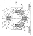
- Fig. 1 of the drawing thus shows fully schematically one embodiment of the glide bearing in accordance with the invention as applied to supporting of a roll, which roll forms a nip with a backup roll.
- the roll itself has been illustrated with a line of dots and dashes and denoted with the reference numeral 1, and the axle of the roll is denoted with the reference numeral 3.
- the reference numeral 2 denotes the backup roll which forms a nip N with the roll 1, which nip is, for instance, a calendering nip.
- the nip plane is denoted by the reference sign A ⁇ A.
- journalling of the roll 1 the journalling of at least one end of the roll must comprise an axial bearing receiving axial loads because the glide bearing arrangement in accordance with the invention is intended to serve mainly merely as a radial bearing of the roll.
- the glide bearing arrangement in accordance with the invention shown in Fig. 1 comprises bearing elements 10,20,30,40 which are mounted in a bearing block 4 and which rest against the axle 3 of the roll.
- the journalling arrangement comprises a main bearing 10,30 which acts in the main loading direction, i.e. in the direction of the nip plane A ⁇ A, and which is loaded towards the nip N, a counter-bearing 20 acting in an opposite direction, and side bearings 40 acting in opposite directions in a direction transverse to the nip plane A ⁇ A.
- a main bearing 10,30 which acts in the main loading direction, i.e. in the direction of the nip plane A ⁇ A, and which is loaded towards the nip N
- a counter-bearing 20 acting in an opposite direction
- side bearings 40 acting in opposite directions in a direction transverse to the nip plane A ⁇ A.
- the main bearing is divided into three parts such that it comprises a first bearing element 10 acting in the nip plane and, in addition to this, second bearing elements 30 arranged at an angle and situated symmetrically with respect to the nip plane.
- the arrangement of the bearing elements on the axle of the roll and, for instance, the "symmetricalness" of the elements may, however, even substantially differ from the illustration of Fig. 1 according to each particular application, as shown, for instance, hereafter in connection with Figs. 2 ⁇ 4.
- the arrangement of the bearing elements shown in Fig. 1 is only one embodiment which is primarily intended for a construction in which the roll 1 provided with said bearings each time forms only one nip with the backup roll. This is the case, for instance, in a soft calender comprising two rolls. However, it is not desired to exclude the possibility that this kind of journalling is also employed in another connection, as is attempted to be illustrated, for instance, by means of Fig. 2.
- the first bearing element 10 and the second bearing elements 30 may be in structure similar to one another such that they comprise a cylinder 11,31 fitted in the bearing block 4, a loading piston 13,33 being movably disposed in said cylinder.
- a pressure space 12,32 is formed in the cylinder 11,31 under the loading piston 13,33, and by passing a pressure medium into said pressure space, the loading piston 13,33 is caused to be loaded towards the axle 3.
- a bearing shoe 16,36 is attached to that end of the loading piston 13,33 which is on the side of the axle 3, and lubricating oil pockets 15,35 opening towards the axle 3 are formed in said bearing shoe.
- the loading piston 13,33 is provided with capillary through bores 14,34, which thus connect the pressure space 12,32 of the cylinder with the lubricating oil pockets 15,35 of the bearing shoe.
- the pressure medium is thus able to enter the lubricating oil pockets 15,35 through the capillary bores 14,34 so that an oil film is formed between the bearing shoe 16,36 and the axle 3, the bearing shoe 16,36 being supported against the axle 3 through said oil film.
- the counter-bearing 20 is in structure similar to the bearing elements 10, 30 of the main bearing such that the counter-bearing element 20 comprises a cylinder 21 fitted in the bearing block 4 and a loading piston 23 movably disposed in the cylinder.
- the loading piston 23 further comprises a bearing shoe 26 which is provided with lubricating oil pockets 25.
- the bearing shoe 26 is provided with capillary bores 24, along which oil from a pressure space 22 situated under the loading piston 23 can enter lubricating oil pockets 25 to form an oil film between the bearing shoe 26 and the neck of the axle 3.
- the counter-bearing element 20 is mounted in the nip plane A ⁇ A such that its direction of action is parallel to the nip plane but opposite to the direction of action of the main bearing.
- Fig. 1 further shows that the axle 3 is supported by means of bearings acting in a direction transverse to the nip plane A ⁇ A, i.e. by means of side bearings 40.
- the side bearings 40 comprise a frame part 42 fitted in the bearing block 4 and a bearing shoe 41 disposed on support of the frame part.
- the bearing shoes 41 are loaded by means of hydraulic fluid against the axle 3 of the roll.
- the actual purpose of the side bearings 40 is only to maintain the axle 3 in its proper position and to attenuate vibrations in a transverse direction.
- the loading of the roll nip N is produced by means of the bearing elements 10,30 of the main bearing. Owing to this, the nip load can be calculated directly from the oil pressures of the bearing elements 10,30. Thus, precise regulation of the nip load can be accomplished by fairly simple steps in the arrangement in accordance with the invention.
- the main bearing is divided into three separate bearing elements 10,30, because of which the bearing can provide, when needed, fairly high loading forces. In present-day soft calenders, in many cases, it must be possible to apply in linear load a range that corresponds to the zero load of the bearing.
- the zero load situation does not pose any problem, since the adjustment of loading to the zero loading situation is easy to accomplish and to provide by means of the main bearing 10,30 and the counter-bearing element 20.
- the bearing elements 10,20,30 are not fixedly secured with respect to the bearing block 4, but each of the bearing elements is movable. Because of this, vibrations can be effectively attenuated.
- opening and closing of the nip N may be taken care of by means of the bearing elements.
- the bearing element may then also be used for quick-opening of the set of rolls.
- the glide bearing arrangement shown in Fig. 1 is also suitable for use in rolls that are loaded from outside by two nips which have a common nip plane, i.e. in which the nips are in the same plane.
- Such applications are in certain types of calenders and presses. In that case there may be several rolls in a common nip plane (e.g. supercalenders, and machine and soft calenders comprising many nips). If such an arrangement were desired to be illustrated by means of Fig. 1, it might be done most simply by adding a second nip roll underneath the roll 1, the nip formed by said nip roll with the roll 1 being in the same nip plane with the nip N between the backup roll 2 and the roll 1.
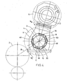
- Fig. 2 schematically shows the application of a glide bearing arrangement to a centre roll of a press, which roll is denoted with the reference numeral 1 in Fig. 2.
- the centre roll 1 forms press nips N 1 ,N 2 (two nips) with backup rolls 2 and 5 such that said nips N 1 ,N 2 are not situated in a common nip plane, but nip planes B ⁇ B and C ⁇ C form an angle with each other. Consequently, the centre roll 1 and thus its bearings are subjected to substantial loads in two different directions, with the result that there exists no actual principal loading direction for the roll.
- the bearing elements 10,20,30,40 have to be grouped so that they receive the applied loads in the best possible way.
- the grouping of the bearing elements corresponds to that described in more detail in Fig.
- the main bearing elements 10,30 and the counter-bearing elements 20 do not act in the direction of either of the nip planes B-B, C-C nor in the direction of the vertical plane, but, instead, the bearing element 10,20,30,40 groups are placed around the neck of the axle 3 in a position required by the "imaginary principal loading direction".
- the arrangement shown in Fig. 3 corresponds to the application of the glide bearing arrangement shown in Fig. 2 to a centre roll of a press, which roll is denoted with the reference numeral 1 in Fig. 3 too.
- the centre roll 1 forms press nips N 1 ,N 2 (two nips) with backup rolls 2 and 5 so that said nips N 1 ,N 2 are not situated in a common nip plane, but nip planes B ⁇ B and C-C form an angle with each other. Consequently, the centre roll 1 and thus its bearings are subjected to substantial loads in two different directions, with the result that there exists no actual principal loading direction for the roll in the arrangement of Fig. 3, either.
- the grouping of the glide bearing elements 10,20,30,40 differs from that of Fig. 2, firstly, so that the so-called counter-bearing element 20 does not act in a direction opposite to the imaginary resultant force of the "main bearing elements" 10,30, and, secondly, so that the groups of the bearing elements are placed around the neck of the axle 3 in a position different from that of Fig. 2.
- the "counter-bearing element” 20 is arranged almost in the nip plane B ⁇ B of the first nip N 1 , and thus said counter-bearing element 20 substantially receives the forces directed to the centre roll 1 in the direction of the first nip plane B ⁇ B.
- the "main bearing elements" 10,30 are in turn arranged so that they receive the load caused by the weight of the centre roll 1 itself as well as the load directed to the bearings through the second nip N 2 in the direction of the second nip plane C-C.
- the most appropriate grouping of the bearing elements 10,20,30,40 depends, as already previously stated, on the forces acting on the bearings of the centre roll 1 in the directions of the nip planes B ⁇ B, C-C and on the effect of the weight of the centre roll 1 itself.
- Fig. 4 shows, in a way corresponding to Figs. 2 and 3, the application of a glide bearing arrangement to journalling of a centre roll 1 of a press, however, differing from said figures in such a way that, in the illustration of Fig. 4, the first nip N 1 is formed between the centre roll 1 and a first backup roll 2 in a way corresponding to Figs. 2 and 3, but the second nip N 2 of the press is an extended nip which is formed between the centre roll 1 and a belt mantle roll 5 provided as a second backup roll.
- the directions of nip planes B ⁇ B, C ⁇ C differ substantially from each other in the embodiment of Fig. 4 too.
- an extended nip causes problems of its own in journalling of a roll especially for the reason that both of the rolls forming such an extended nip are subjected to very high forces from the nip.
- this has been taken into account such that the main bearing elements 10,30 in the journalling of the centre roll 1 are arranged to act in the nip plane C-C of the extended nip N 2 between the centre roll 1 and the belt mantle roll 5.
- a counter-bearing element 20 is also mounted to act in a direction opposite to said second nip plane C ⁇ C with respect to the main bearing elements 10,30.
- journalling system in the embodiment of Fig. 4 is provided further with an additional element 50 which is arranged to act almost in the direction of the first nip plane B-B so that said additional bearing element 50 substantially receives together with the counter-bearing element 20 the load directed to the bearings from the first nip N 1 .
- journalling arrangement for the centre roll 1 of the press shown in Figs. 2 ⁇ 4 and differing from the arrangement shown in Fig. 1, intended for journalling a calender roll in particular, is that in the centre roll application the journalling arrangement is intended only for journalling of the roll, and the nips are not intended to be opened and closed by means of the bearing elements, but the opening and the closing are intended to be taken care of by other more conventional means. It would indeed be difficult to accomplish the opening and the closing of the nips in the arrangements shown in Fig. 2 ⁇ 4 because the centre roll forms two nips while the nip planes pass substantially across each other.
Abstract
Description
Claims (8)
- A roll for a paper machine or paper finishing device comprising at least one backup roll (2, 5), said roll (1) being provided with a roll axle (3) and glide bearings and being mounted revolvingly in a frame member such as a bearing block (4) which roll is a nip roll and forms a roll nip (N, N1, N2) and a nip plane (A-A, B-B, C-C) with said at least one backup roll (2, 5) whereby the glide bearings of the roll (1) comprise several hydrostatic bearing elements (10, 20, 30, 40) provided with bearing shoes (16, 26, 36, 41) positioned around the neck of the roll axle (3) for supporting said axle (3) and thus the roll (1) revolvingly with respect to said frame member whereby the bearing elements (10, 20, 30, 40) are hydraulically operating piston-cylinder devices loadable by means of a pressure medium so that each of the bearing shoes (16, 26, 36, 41) of the bearing elements is able to be positioned freely around the neck of the axle (3) characterized in that the bearing elements (10, 30) constituting the main bearing of the roll comprise several bearing elements (10, 30) placed around the periphery of the axle (3) the resultant of the forces produced by said bearing elements being opposite in direction to the resultant of the force directed to the bearings from the roll nip (N) in the direction of the nip plane (A-A) and of the force directed to the bearings from the weight of the roll (1).
- A roll as claimed in claim 1 characterized in that at least in the principal loading direction of the roll in particular in the direction of a nip plane (A-A) the roll (1) is displaceable by means of bearing elements (10, 20, 30) especially for the purpose of closing and opening the nip (N).
- A roll as claimed in claims 1 or 2 characterized in that the loading pressure of the roll nip (N) is arranged to be produced by means of bearing elements (10, 30) acting in the direction of the nip plane (A-A).
- A roll as claimed in any one of the preceding claims characterized in that the loading of the roll nip (N) is determined directly from the pressure of a hydraulic medium of the bearing elements (10, 20, 30) acting in the direction of the nip plane (A-A) and regulated according to it to a desired level.
- A roll as claimed in any one of the preceding claims characterized in that the main bearing of the roll comprises three bearing elements (10, 30) of which one bearing element (10) is arranged to act directly in the direction of the resultant force and the other two bearing elements (30) symmetrically with respect to said bearing element (10).
- A roll as claimed in any one of the preceding claims characterized in that the roll is a calender roll or a press roll which roll (1) is loaded from outside radially from two directions through roll nips the nip planes of which roll nips substantially coincide.
- A roll as claimed in any one of claims 1 to 5 characterized in that the roll is a centre roll or an equivalent roll (1) of a press which roll (1) is loaded from outside radially from at least two different directions through roll nips (N1, N2) the directions of whose nip planes (B-B, C-C) pass across and intersect each other whereby the bearing elements (10, 20, 30, 40, 50) of the glide bearing are arranged and grouped on the neck of the axle (3) so that they receive the loads coming from the directions of the nip planes (B-B, C-C) and compensate for the load directed to the bearings from the weight of the roll (1).
- A roll as claimed in claim 6 or 7 characterized in that one of the nips producing an external load on the roll (1) is for instance an extended nip (N2) provided by means of a belt mantle roll (5) most of the bearing elements (10, 20, 30) of the glide bearing being arranged to act in the direction of the nip plane (C-C) of said extended nip (N2).
Applications Claiming Priority (3)
| Application Number | Priority Date | Filing Date | Title |
|---|---|---|---|
| FI970624 | 1997-02-14 | ||
| FI970624A FI117486B (en) | 1997-02-14 | 1997-02-14 | Roller for a paper machine or paper finishing machine |
| PCT/FI1998/000086 WO1998036184A1 (en) | 1997-02-14 | 1998-01-28 | Hydrostatic glide bearing for a roll or equivalent |
Publications (2)
| Publication Number | Publication Date |
|---|---|
| EP0897484A1 EP0897484A1 (en) | 1999-02-24 |
| EP0897484B1 true EP0897484B1 (en) | 2005-07-27 |
Family
ID=8548204
Family Applications (1)
| Application Number | Title | Priority Date | Filing Date |
|---|---|---|---|
| EP98902002A Expired - Lifetime EP0897484B1 (en) | 1997-02-14 | 1998-01-28 | Hydrostatic glide bearing for a roll or equivalent |
Country Status (9)
| Country | Link |
|---|---|
| US (1) | US6129453A (en) |
| EP (1) | EP0897484B1 (en) |
| JP (1) | JP2000509133A (en) |
| KR (1) | KR100444109B1 (en) |
| AT (1) | ATE300683T1 (en) |
| AU (1) | AU5866598A (en) |
| DE (1) | DE69830956T2 (en) |
| FI (1) | FI117486B (en) |
| WO (1) | WO1998036184A1 (en) |
Cited By (1)
| Publication number | Priority date | Publication date | Assignee | Title |
|---|---|---|---|---|
| DE102015212285B3 (en) * | 2015-07-01 | 2016-10-27 | Schaeffler Technologies AG & Co. KG | Linear guide system and method for performing measurements on a linear guide system |
Families Citing this family (12)
| Publication number | Priority date | Publication date | Assignee | Title |
|---|---|---|---|---|
| FI103911B (en) * | 1998-06-05 | 1999-10-15 | Valmet Corp | Bearing control device |
| FI104100B (en) | 1998-06-10 | 1999-11-15 | Valmet Corp | Integrated paper machine |
| FI104206B1 (en) * | 1998-06-15 | 1999-11-30 | Valmet Corp | Fast displacement system for hydrostatically stored roller |
| JP4135320B2 (en) * | 1999-03-31 | 2008-08-20 | 株式会社日立製作所 | Strip wiper device, strip wiping method, rolling equipment and rolling method |
| FI116310B (en) * | 2000-05-10 | 2005-10-31 | Metso Paper Inc | Deflection-compensated roll for paper / board or finishing machine |
| FI20002487A0 (en) * | 2000-11-14 | 2000-11-14 | Valmet Corp | Outer slide bearing for a roll to a paper / cardboard or finishing machine |
| US6394387B1 (en) * | 2000-12-22 | 2002-05-28 | Pratt & Whitney Canada Corp. | Rotor shaft support and drive arrangement |
| GB2430986A (en) * | 2005-10-05 | 2007-04-11 | Wind Power Ltd | A bearing arrangement |
| FI20055540A (en) * | 2005-10-07 | 2007-04-08 | Metso Paper Inc | Multi-roll calender sliding bearing |
| US11306611B2 (en) * | 2016-06-29 | 2022-04-19 | Dresser, Llc | Supressing vibrations of shafts using adjustable bearings |
| EP3276192B1 (en) * | 2016-07-29 | 2019-11-27 | Siemens Gamesa Renewable Energy A/S | Bearing arrangement |
| DE102017105577A1 (en) * | 2017-03-15 | 2018-09-20 | Thyssenkrupp Ag | Bearing arrangement and wind turbine |
Family Cites Families (11)
| Publication number | Priority date | Publication date | Assignee | Title |
|---|---|---|---|---|
| FR1382268A (en) * | 1963-11-05 | 1964-12-18 | Loire Atel Forges | Low friction bearing |
| US3422650A (en) * | 1967-02-23 | 1969-01-21 | Bliss Co | Gauge control for a rolling mill |
| DE2010628A1 (en) * | 1970-03-06 | 1971-10-14 | Glyco Metall Werke Daelen & So | Tube mill |
| GB1343518A (en) * | 1970-11-30 | 1974-01-10 | Ifield Lab Pty Ltd | Journal support bearings for rotating shafts |
| SE368854B (en) * | 1972-11-03 | 1974-07-22 | Skf Ind Trading & Dev | |
| US3891281A (en) * | 1974-04-08 | 1975-06-24 | Allis Chalmers | Pivoted pad bearing apparatus and method for bidirectional rotation |
| CH587688A5 (en) * | 1975-02-13 | 1977-05-13 | Escher Wyss Ag | |
| CH598501A5 (en) * | 1975-12-02 | 1978-04-28 | Escher Wyss Ag | |
| CH659865A5 (en) * | 1982-07-30 | 1987-02-27 | Escher Wyss Ag | HYDROSTATIC SUPPORT ELEMENT AND ITS USE IN A ROLLING DEVICE. |
| CH662754A5 (en) * | 1984-03-01 | 1987-10-30 | Escher Wyss Ag | TREATMENT MACHINE WITH ROTATABLE TREATMENT DRUM. |
| DE4319579C2 (en) * | 1993-06-14 | 1996-12-19 | Kleinewefers Gmbh | Bearing for a heated roller |
-
1997
- 1997-02-14 FI FI970624A patent/FI117486B/en not_active IP Right Cessation
-
1998
- 1998-01-28 JP JP10535387A patent/JP2000509133A/en active Pending
- 1998-01-28 AT AT98902002T patent/ATE300683T1/en active
- 1998-01-28 DE DE69830956T patent/DE69830956T2/en not_active Expired - Lifetime
- 1998-01-28 US US09/171,165 patent/US6129453A/en not_active Expired - Fee Related
- 1998-01-28 EP EP98902002A patent/EP0897484B1/en not_active Expired - Lifetime
- 1998-01-28 WO PCT/FI1998/000086 patent/WO1998036184A1/en active IP Right Grant
- 1998-01-28 KR KR10-1998-0708148A patent/KR100444109B1/en not_active IP Right Cessation
- 1998-01-28 AU AU58665/98A patent/AU5866598A/en not_active Abandoned
Cited By (1)
| Publication number | Priority date | Publication date | Assignee | Title |
|---|---|---|---|---|
| DE102015212285B3 (en) * | 2015-07-01 | 2016-10-27 | Schaeffler Technologies AG & Co. KG | Linear guide system and method for performing measurements on a linear guide system |
Also Published As
| Publication number | Publication date |
|---|---|
| FI970624A0 (en) | 1997-02-14 |
| EP0897484A1 (en) | 1999-02-24 |
| JP2000509133A (en) | 2000-07-18 |
| FI970624A (en) | 1998-08-15 |
| US6129453A (en) | 2000-10-10 |
| KR20000064894A (en) | 2000-11-06 |
| AU5866598A (en) | 1998-09-08 |
| FI117486B (en) | 2006-10-31 |
| DE69830956T2 (en) | 2006-05-24 |
| ATE300683T1 (en) | 2005-08-15 |
| KR100444109B1 (en) | 2005-05-17 |
| WO1998036184A1 (en) | 1998-08-20 |
| DE69830956D1 (en) | 2005-09-01 |
Similar Documents
| Publication | Publication Date | Title |
|---|---|---|
| EP0897484B1 (en) | Hydrostatic glide bearing for a roll or equivalent | |
| US4793250A (en) | Method and apparatus for controlling deflection of an adjustable crown roll | |
| CA1263551A (en) | Pressure roll for use in calenders or the like | |
| JP2543124Y2 (en) | Variable crown roll | |
| US5029521A (en) | Calender and method of operating the same | |
| EP0332594B1 (en) | Variable-crown roll | |
| US5018258A (en) | Support system for a variable-crown roll | |
| JP4101881B2 (en) | A method for quickly opening a series of rolls in a calendar, in particular a supercalender, and a hydraulic device for a series of rolls in a calendar, in particular a supercalender. | |
| EP1155190B1 (en) | Method and device for changing the natural frequency of a nip roll construction in a paper or board machine | |
| CA1070535A (en) | Deflection-compensated, preferably soft-surface roll for use in a calender | |
| US4856155A (en) | Method and device in an adjustable-crown roll | |
| US5896813A (en) | Gradient calender | |
| EP0886696B1 (en) | A tubular roll provided with hydraulically loaded glide bearings | |
| CA2249382C (en) | Hydrostatic glide bearing for a roll or equivalent | |
| US4757586A (en) | Glide-shoe arrangement for a variable-crown roll | |
| US3525301A (en) | Calender stack | |
| JPH0361847B2 (en) | ||
| US3418703A (en) | Antideflection roll with non-rotating beam and lever supports | |
| FI80772B (en) | Method in a bend-adjusted roll and a bend-adjusted roll | |
| WO2001021889A1 (en) | Method and arrangement for control of rolls in a calender | |
| FI74525C (en) | STOEDARRANGEMANG MELLAN GLIDSKORNA OCH BELASTNINGSKOLVARNA AV EN ZONREGLERBAR VALS. | |
| FI81184C (en) | BOEJNINGSKOMPENSERAD VALS. | |
| WO2006100345A1 (en) | Calender and a method in calendering fibre web, especially paper or board web | |
| JPH0665889A (en) | Variable crown roll for high rolling reduction |
Legal Events
| Date | Code | Title | Description |
|---|---|---|---|
| PUAI | Public reference made under article 153(3) epc to a published international application that has entered the european phase |
Free format text: ORIGINAL CODE: 0009012 |
|
| 17P | Request for examination filed |
Effective date: 19981009 |
|
| AK | Designated contracting states |
Kind code of ref document: A1 Designated state(s): AT DE FI FR GB IT SE |
|
| RAP1 | Party data changed (applicant data changed or rights of an application transferred) |
Owner name: VALMET CORPORATION(REG.NO.763281) |
|
| REG | Reference to a national code |
Ref country code: IE Ref legal event code: MM4A |
|
| RAP1 | Party data changed (applicant data changed or rights of an application transferred) |
Owner name: METSO PAPER, INC. |
|
| RAP1 | Party data changed (applicant data changed or rights of an application transferred) |
Owner name: METSO PAPER, INC. |
|
| 17Q | First examination report despatched |
Effective date: 20020924 |
|
| GRAP | Despatch of communication of intention to grant a patent |
Free format text: ORIGINAL CODE: EPIDOSNIGR1 |
|
| GRAS | Grant fee paid |
Free format text: ORIGINAL CODE: EPIDOSNIGR3 |
|
| GRAA | (expected) grant |
Free format text: ORIGINAL CODE: 0009210 |
|
| AK | Designated contracting states |
Kind code of ref document: B1 Designated state(s): AT DE FI FR GB IT SE |
|
| PG25 | Lapsed in a contracting state [announced via postgrant information from national office to epo] |
Ref country code: IT Free format text: LAPSE BECAUSE OF FAILURE TO SUBMIT A TRANSLATION OF THE DESCRIPTION OR TO PAY THE FEE WITHIN THE PRESCRIBED TIME-LIMIT;WARNING: LAPSES OF ITALIAN PATENTS WITH EFFECTIVE DATE BEFORE 2007 MAY HAVE OCCURRED AT ANY TIME BEFORE 2007. THE CORRECT EFFECTIVE DATE MAY BE DIFFERENT FROM THE ONE RECORDED. Effective date: 20050727 Ref country code: FI Free format text: LAPSE BECAUSE OF FAILURE TO SUBMIT A TRANSLATION OF THE DESCRIPTION OR TO PAY THE FEE WITHIN THE PRESCRIBED TIME-LIMIT Effective date: 20050727 |
|
| REG | Reference to a national code |
Ref country code: GB Ref legal event code: FG4D |
|
| REF | Corresponds to: |
Ref document number: 69830956 Country of ref document: DE Date of ref document: 20050901 Kind code of ref document: P |
|
| PG25 | Lapsed in a contracting state [announced via postgrant information from national office to epo] |
Ref country code: SE Free format text: LAPSE BECAUSE OF FAILURE TO SUBMIT A TRANSLATION OF THE DESCRIPTION OR TO PAY THE FEE WITHIN THE PRESCRIBED TIME-LIMIT Effective date: 20051027 |
|
| PLBE | No opposition filed within time limit |
Free format text: ORIGINAL CODE: 0009261 |
|
| STAA | Information on the status of an ep patent application or granted ep patent |
Free format text: STATUS: NO OPPOSITION FILED WITHIN TIME LIMIT |
|
| 26N | No opposition filed |
Effective date: 20060428 |
|
| EN | Fr: translation not filed | ||
| PG25 | Lapsed in a contracting state [announced via postgrant information from national office to epo] |
Ref country code: FR Free format text: LAPSE BECAUSE OF FAILURE TO SUBMIT A TRANSLATION OF THE DESCRIPTION OR TO PAY THE FEE WITHIN THE PRESCRIBED TIME-LIMIT Effective date: 20060922 |
|
| PGFP | Annual fee paid to national office [announced via postgrant information from national office to epo] |
Ref country code: GB Payment date: 20080124 Year of fee payment: 11 |
|
| PG25 | Lapsed in a contracting state [announced via postgrant information from national office to epo] |
Ref country code: FR Free format text: LAPSE BECAUSE OF FAILURE TO SUBMIT A TRANSLATION OF THE DESCRIPTION OR TO PAY THE FEE WITHIN THE PRESCRIBED TIME-LIMIT Effective date: 20050727 |
|
| GBPC | Gb: european patent ceased through non-payment of renewal fee |
Effective date: 20090128 |
|
| PG25 | Lapsed in a contracting state [announced via postgrant information from national office to epo] |
Ref country code: GB Free format text: LAPSE BECAUSE OF NON-PAYMENT OF DUE FEES Effective date: 20090128 |
|
| PGFP | Annual fee paid to national office [announced via postgrant information from national office to epo] |
Ref country code: DE Payment date: 20170120 Year of fee payment: 20 |
|
| PGFP | Annual fee paid to national office [announced via postgrant information from national office to epo] |
Ref country code: AT Payment date: 20170123 Year of fee payment: 20 |
|
| REG | Reference to a national code |
Ref country code: DE Ref legal event code: R071 Ref document number: 69830956 Country of ref document: DE |
|
| REG | Reference to a national code |
Ref country code: AT Ref legal event code: MK07 Ref document number: 300683 Country of ref document: AT Kind code of ref document: T Effective date: 20180128 |