EP0896899A2 - Heckleuchte von Kraftfahrzeugen - Google Patents
Heckleuchte von Kraftfahrzeugen Download PDFInfo
- Publication number
- EP0896899A2 EP0896899A2 EP98113338A EP98113338A EP0896899A2 EP 0896899 A2 EP0896899 A2 EP 0896899A2 EP 98113338 A EP98113338 A EP 98113338A EP 98113338 A EP98113338 A EP 98113338A EP 0896899 A2 EP0896899 A2 EP 0896899A2
- Authority
- EP
- European Patent Office
- Prior art keywords
- voltage
- current
- rear light
- light according
- leds
- Prior art date
- Legal status (The legal status is an assumption and is not a legal conclusion. Google has not performed a legal analysis and makes no representation as to the accuracy of the status listed.)
- Granted
Links
Images


Classifications
-
- B—PERFORMING OPERATIONS; TRANSPORTING
- B60—VEHICLES IN GENERAL
- B60Q—ARRANGEMENT OF SIGNALLING OR LIGHTING DEVICES, THE MOUNTING OR SUPPORTING THEREOF OR CIRCUITS THEREFOR, FOR VEHICLES IN GENERAL
- B60Q11/00—Arrangement of monitoring devices for devices provided for in groups B60Q1/00 - B60Q9/00
- B60Q11/005—Arrangement of monitoring devices for devices provided for in groups B60Q1/00 - B60Q9/00 for lighting devices, e.g. indicating if lamps are burning or not
-
- B—PERFORMING OPERATIONS; TRANSPORTING
- B60—VEHICLES IN GENERAL
- B60Q—ARRANGEMENT OF SIGNALLING OR LIGHTING DEVICES, THE MOUNTING OR SUPPORTING THEREOF OR CIRCUITS THEREFOR, FOR VEHICLES IN GENERAL
- B60Q1/00—Arrangement of optical signalling or lighting devices, the mounting or supporting thereof or circuits therefor
- B60Q1/26—Arrangement of optical signalling or lighting devices, the mounting or supporting thereof or circuits therefor the devices being primarily intended to indicate the vehicle, or parts thereof, or to give signals, to other traffic
- B60Q1/2696—Mounting of devices using LEDs
-
- H—ELECTRICITY
- H05—ELECTRIC TECHNIQUES NOT OTHERWISE PROVIDED FOR
- H05B—ELECTRIC HEATING; ELECTRIC LIGHT SOURCES NOT OTHERWISE PROVIDED FOR; CIRCUIT ARRANGEMENTS FOR ELECTRIC LIGHT SOURCES, IN GENERAL
- H05B45/00—Circuit arrangements for operating light-emitting diodes [LED]
- H05B45/10—Controlling the intensity of the light
-
- H—ELECTRICITY
- H05—ELECTRIC TECHNIQUES NOT OTHERWISE PROVIDED FOR
- H05B—ELECTRIC HEATING; ELECTRIC LIGHT SOURCES NOT OTHERWISE PROVIDED FOR; CIRCUIT ARRANGEMENTS FOR ELECTRIC LIGHT SOURCES, IN GENERAL
- H05B45/00—Circuit arrangements for operating light-emitting diodes [LED]
- H05B45/50—Circuit arrangements for operating light-emitting diodes [LED] responsive to malfunctions or undesirable behaviour of LEDs; responsive to LED life; Protective circuits
- H05B45/56—Circuit arrangements for operating light-emitting diodes [LED] responsive to malfunctions or undesirable behaviour of LEDs; responsive to LED life; Protective circuits involving measures to prevent abnormal temperature of the LEDs
Definitions
- the invention relates to a rear light of motor vehicles the preamble of claim 1.
- LED lights are only available as high-mounted brake lights Motor vehicles used.
- the adaptation of the LEDs to the vehicle voltage is realized via series resistors. It can under certain operating conditions to a current overload and a temperature overload of the LEDs. The consequence of Overloading can decrease the light output until failure or be a change in light color.
- the invention has for its object the generic Train tail light so that it is in any operating condition of the Motor vehicle works reliably.
- At least one of them Lights, preferably all lights, formed by LEDs.
- the operating current the LEDs will at least have a voltage range kept approximately constant. This means that there is no power overload and / or temperature overload of the LEDs. Your light output therefore remains at least approximately constant over the period of use. There is also no change in their light color.
- the control device is for the operation of a rear light Motor vehicle provided, which has LEDs as illuminants. With the control device is preferably a constant brightness of the LEDs over the entire voltage curve.
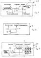
- the control device has an interface 1 (FIG. 1), via which the control electronics receive a function signal from the vehicle electrical system. It activates the control device with which the assigned LEDs are then controlled. Downstream of the interface 1 is a supply voltage regulator 2, with which the control device generates its supply voltage from the control signal supplied via the interface 1.
- the supply voltage regulator 2 is designed so that the quiescent current consumption is less than 1 mA.
- the supply voltage regulator 2 is followed by a constant current regulator 3 to 5 with the interposition of a diode 42.
- the constant current regulator 3 is assigned to the brake light 6, the constant current regulator 4 to the flashing light 7 and the constant current regulator 5 to the tail light 8 of the rear light.
- the constant current controllers 3 to 5 are each of identical design and measure the current at a measuring resistor 9 (FIG. 5). The measured resistance is compared with a reference voltage 11 by means of a comparator 10. The output signal of the comparator 10 is fed to an actuator 12, which is preferably a power MOSFET. An LED matrix 13 is regulated via this actuator 12 with the interposition of a protective diode 14. The control device monitors the vehicle electrical system voltage. If a predetermined voltage value U max is exceeded, the constant current controller 3 to 5 switches to a definable safe state in order to prevent the actuator 12 from being overloaded. The constant current controller 3 to 5 has a corresponding connection 15 for overvoltage protection. The constant current controller 3 to 5 is advantageously designed for a working range from 9 volts to 16 volts.
- a common overvoltage protection 16 is assigned to the constant current regulators 3 to 5 in order to prevent overloading of the actuator 12 of the respective constant current regulator 3 to 5.
- the overvoltage protection 16 has an actuator 17 in the form of a transistor.
- a resistor 18 and a protective diode 19 are connected upstream of it. The voltage is specified with the resistor 18.
- the overvoltage protection 16, as shown in FIG. 1, is connected to the interface 1 of the control device.
- the respective constant current controller 3 to 5 is switched via the actuator 17 of the overvoltage protection 16 in such a way that an overload of the actuator 12 of the respective constant current controller 3 to 5 is excluded.
- an LED failure detection 20 Via the supply voltage regulator 2 is at the interface 1 an LED failure detection 20 connected. It is the flashing light 7 assigned and monitors the failure of an LED of the flashing light 7, which is formed by an LED matrix. 7 shows the LED matrix 21, which forms the flashing light 7.
- the LED matrix 21 is as Quad matrix formed, which has four rows with four LEDs each. An actual value is tapped on the LED matrix 21, i.e. it will be the Tension across the upper and lower half of the matrix using a Comparator 22 compared. It receives the one measured on the LED matrix 21 Actual voltage value and compares it with one over one Voltage divider 23 supplied target voltage value. Are all LEDs of the LED matrix 21 in order, is only a component-related minor Deviation between the voltages of the upper and the lower half of the matrix.
- Comparator 22 then outputs a corresponding output signal that can be evaluated.
- This output signal 24 of the comparator 22 is fed to the interface 1 via which, for example triggered an optical and / or acoustic signal in the motor vehicle can be, which indicates to the driver that at least one LED in the flashing light 7 has failed.
- the failure detection 20 described can also be used for the brake light 6 or the tail light 8 are used.
- a total failure of a function of the rear light of the motor vehicle for example due to a cable break or a connector damage total failure detection 25 is provided (Fig. 1 and 4) to which the constant current regulator 3 to 5 Brake light, the flashing light 7 and the tail light 8 connected are.
- the output signal 26 of the total failure detection 25 is fed to the interface 1.
- An optical and / or an acoustic signal is triggered in the vehicle, to alert the driver that the rear light of the motor vehicle has failed completely.
- the total failure detection 25 has a comparator 27 (FIG. 4) which compares a reference voltage 28 with an actual voltage value, by means of the measuring resistor 9 of the respective constant current regulator 3 to 5 is measured. If the rear light fails, the Comparator 27, the output signal 26, which is fed to the interface 1 becomes.
- the tail light 8 is assigned a low voltage stage 29, the ensures that the tail light 8 below a limit voltage for example, switched from a four matrix to a two matrix becomes.
- the tail light 8 by a LED matrix 30 formed of a relay 31 with a coil 32 and Switch contacts 33 and a diode 43 are connected upstream.
- the relay 31 is controlled via an actuator 34, preferably a transistor.
- a relay 35 is connected upstream of the relay 31 Target voltage value 36 with a measured actual voltage value 37 compares.
- a voltage divider consists of two for voltage detection resistors 38, 39 connected in series are provided.
- the setpoint is formed by a resistor 40 and a Zener diode 41.
- the current control is preferably approximately for a working range 9 volts to about 16 volts.
- the control electronics themselves work down to one Voltage of 5.1 volts in the exemplary embodiment. This toggle function can, if desired, also for the brake light 6 and / or the flashing light 7 are used.
- the tail light 8 Around the matrix of four 30 the tail light 8 to switch to the matrix of two, it will Relay 31 switched over the actuator 34.
- the tail light 8 has two current levels.
- the tail light can be one Tail light function and a brake function.
- a low current is sufficient for the tail light function.
- For the braking function a high current is required because the LEDs for the tail light 8 can be controlled together with the LEDs of the brake light 7.
- the current value can be changed by changing the default voltage divider of the respective constant current controller 3 to 5 can be freely set.
- the level switching is done by connecting an additional one in parallel Resistance at the voltage divider reached.
- the setting of at least two current levels and their control by different signals is also with the brake light 6 and / or with flashing light 7 possible.
- the brake light 6, the flashing light 7 and the tail light 8 forming LEDs are advantageously arranged in matrix form. This has the Advantage that if one LED fails, the other LEDs continue to work to shine. If no value is placed on this security, the LEDs can also be connected in series, as shown in FIGS. 2a to 2c.
- Fig. 2a shows the possibility of the LEDs in rows of five parallel to each other to switch.
- Fig. 2b shows four LEDs connected in series, while 2c shows that the LEDs are also in a row of two can be arranged.
- the LEDs are in a five-matrix, according to FIG. 2e arranged in a four matrix and according to FIG. 2f in a two matrix.
- the brake light 6, the flashing light 7 and the tail light 8 advantageously a four matrix chosen to be at a forward voltage of about 2.5 volts per LED as little power loss as possible at the actuator 14 of the respective constant current regulator Get 3 to 5.
- At other operating voltages or LEDs with other forward voltages are also two, Three, five or other matrix arrangements of the LEDs are possible.
- the current for the LEDs of the various lights of the rear light of the motor vehicle is kept constant by a control over a certain voltage range.
- the current detection in the respective current controllers 3 to 5 takes place in each case via the transmitter 9 in the form of a measuring resistor.
- the current control can have several freely adjustable current levels, as has been explained by way of example for the tail light 8 with reference to FIG. 3.
- the different current levels are set via a variable divider ratio of the various resistors 38 to 40 of the low-voltage stage 29.
- the current regulators 3 to 5 are protected against overvoltage.
- the current regulators 3 to 5 are brought into a defined state in which there is no danger for the LEDs of the brake light 6, the flashing light 7 and the tail light 8 and for the current regulators 3 to 5 consists.
- the tail light 8 can be operated up to a voltage of U min , since from a switching threshold the four matrix 30 used as an example for the tail light 8 is switched to a two matrix. For example, the operation of the tail light 8 as a four-LED matrix is only possible from a voltage of, for example, 3.5 volts above rpm .
- the current for the brake light 6, the flashing light 7 and the tail light 8 is monitored and displayed by the total failure detection 25.
- the LED failure detection 20 monitors the voltage across the two halves of the LED matrix 21 in order to detect the failure of individual LEDs. If an LED fails in the LED matrix 21, this is noticeable by an increase in the voltage drop on the corresponding matrix half. Since the operating current for the LEDs is kept constant within a certain voltage range, an optimal luminous efficacy of the LEDs is obtained. The chip temperature of the LEDs can also be kept very low, so that the LEDs have a long service life.
Landscapes
- Engineering & Computer Science (AREA)
- Mechanical Engineering (AREA)
- Lighting Device Outwards From Vehicle And Optical Signal (AREA)
Abstract
Description
- Fig. 1
- ein Blockschaltbild einer erfindungsgemäßen Steuereinrichtung für LEDs,
- Fig. 2a bis Fig. 2f
- verschiedene Schaltungsbeispiele für in Gruppen angeordnete LEDs,
- Fig. 3
- das Schaltbild einer Niederspannungsstufe der erfindungsgemäßen Steuereinrichtung gemäß Fig. 1,
- Fig. 4
- das Schaltbild einer Gesamtausfallerkennung der erfindungsgemäßen Steuereinrichtung gemäß Fig. 1,
- Fig. 5
- das Schaltbild eines Konstantstromreglers der erfindungsgemäßen Steuereinrichtung gemäß Fig. 1,
- Fig. 6
- das Schaltbild eines Überspannungsschutzes der erfindungsgemäßen Steuerungseinrichtung gemäß Fig. 1,
- Fig. 7
- das Schaltbild einer LED-Ausfallerkennung der erfindungsgemäßen Steuereinrichtung gemäß Fig. 1.
Claims (12)
- Heckleuchte von Kraftfahrzeugen, mit einem Brems-, einem Blink- und einem Schlußlicht,
dadurch gekennzeichnet, daß zumindest eines der Lichter (6 bis 8) durch LEDs gebildet ist, die über einen Spannungsbereich mit zumindest annähernd konstantem Strom betrieben werden. - Heckleuchte noch Anspruch 1,
dadurch gekennzeichnet, daß der Strom durch einen Meßwertgebar (9), vorzugsweise einen Meßwiderstand, erfaßt wird. - Heckleuchte nach Anspruch 1 oder 2,
dadurch gekennzeichnet, daß dem Licht (6 bis 8) ein Stromregler (3 bis 5) zugeordnet ist, der einen Spannungssollwert mit einem Spannungsistwert vergleicht, und daß vorzugsweise der Stromregler (3 bis 5) ein Stellglied (12), vorteilhaft ein MOSFET, aufweist, das durch einen Vergleicher (10) des Stromreglers (3 bis 5) steuerbar ist. - Heckleuchte nach Anspruch 3,
dadurch gekennzeichnet, daß der Stromregler (3 bis 5) in wenigstens zwei Strompegel schaltbar ist, und daß vorzugsweise zur Einstellung der Strompegel das Tellerverhältnis von Widerständen (38 bis 40) veranderbar ist. - Heckleuchte nach einem der Ansprüche 1 bis 4,
dadurch gekennzeichnet, daß dem Licht (6 bis 8) ein Überspannungsschutz (16) vorgeschaltet ist, der vorteilhaft ein Stellglied (17), vorzugsweise einen Transistor, aufweist, der bei Überschreiten eines vorgegebenen Spannungswertes (Umax) schaltet. - Heckleuchte nach einem der Ansprüche 1 bis 5,
dadurch gekennzeichnet, daß den Lichtern (6 bis 8) eine Gesamtausfallerkennung (25) zugeordnet ist, die vorzugsweise einen vorgegebenen Spannungswert mit einem Ist-Spannungswert des Stromreglers (3 bis 5) vergleicht. - Heckleuchte nach Anspruch 5 oder 6,
dadurch gekennzeichnet, daß der Überspannungsschutz (16) dem Regler (3 bis 5) vorgeschaltet ist und bei Überschreiten der vorgegebenen Spannung (Umax) den Regler (3 bis 5) in einen Grundzustand schaltet. - Heckleuchte nach einem der Ansprüche 1 bis 7,
dadurch gekennzeichnet, daß zumindest das eine Licht (6 bis 8), vorzugsweise alle Lichter, durch eine LED-Matrix (13, 21, 30) gebildet ist. - Heckleuchte nach einem der Ansprüche 1 bis 8,
dadurch gekennzeichnet, daß eine LED-Ausfallerkennung (20) vorgesehen ist, die den Ausfall einer LED über die Messung eines Spannungsabfalles erfaßt, und daß vorzugsweise der Spannungsabfall über beide Hälften der LED-Matrix (13, 21, 30) gemessen wird. - Heckleuchte nach Anspruch 9,
dadurch gekennzeichnet, daß die Ausfallerkennung (20) einen Vergleicher (22) aufweist, der einen Spannungssollwert mit einem Spannungsistwert vergleicht. - Heckleuchte nach einem der Ansprüche 8 bis 10,
dadurch gekennzeichnet, daß eine Niederspannungsstufe (29) vorgesehen ist, die bei einer Schaltschwelle eine LCD-Matrix (13, 21, 30) mit einer vorgegebenen Zahl von LEDs in eine LED-Matrix mit der Hälfte der LEDs umschaltet, und daß die Niederspannungsstufe (29) vorteilhaft ein Relais (31) zum Umschalten aufweist. - Heckleuchte nach einem der Ansprüche 1 bis 11,
dadurch gekennzeichnet, daß alle Funktionen ihre Versorgungsspannung aus dem Steuersignal beziehen und der Ruhestrom ≤ 1 mA ist.
Applications Claiming Priority (2)
| Application Number | Priority Date | Filing Date | Title |
|---|---|---|---|
| DE19734750A DE19734750C2 (de) | 1997-08-12 | 1997-08-12 | Heckleuchte von Kraftfahrzeugen |
| DE19734750 | 1997-08-12 |
Publications (3)
| Publication Number | Publication Date |
|---|---|
| EP0896899A2 true EP0896899A2 (de) | 1999-02-17 |
| EP0896899A3 EP0896899A3 (de) | 2002-06-19 |
| EP0896899B1 EP0896899B1 (de) | 2009-09-02 |
Family
ID=7838640
Family Applications (1)
| Application Number | Title | Priority Date | Filing Date |
|---|---|---|---|
| EP98113338A Expired - Lifetime EP0896899B1 (de) | 1997-08-12 | 1998-07-17 | Heckleuchte von Kraftfahrzeugen |
Country Status (3)
| Country | Link |
|---|---|
| US (1) | US5896084A (de) |
| EP (1) | EP0896899B1 (de) |
| DE (2) | DE19734750C2 (de) |
Cited By (11)
| Publication number | Priority date | Publication date | Assignee | Title |
|---|---|---|---|---|
| WO2001003474A1 (de) * | 1999-06-30 | 2001-01-11 | Patent-Treuhand-Gesellschaft für elektrische Glühlampen mbH | Ansteuerschaltung für led und zugehöriges betriebsverfahren |
| WO2001030119A1 (de) * | 1999-10-18 | 2001-04-26 | Patent-Treuhand-Gesellschaft für elektrische Glühlampen mbH | Ansteuerschaltung für led und zugehöriges betriebsverfahren |
| EP1244334A2 (de) | 2001-03-22 | 2002-09-25 | Hella KG Hueck & Co. | Schaltungsanordnung für eine LED Leuchte |
| DE10214423A1 (de) * | 2002-03-30 | 2003-10-09 | Hella Kg Hueck & Co | Beleuchtungsschaltkreis, insbesondere für Kraftfahrzeuge |
| FR2845328A1 (fr) * | 2002-10-08 | 2004-04-09 | Koito Mfg Co Ltd | Lampe de vehicule a mode de fonctionnement multiple |
| EP1517588A1 (de) * | 2003-09-17 | 2005-03-23 | Moritex Corporation | Verfahren und Vorrichtung zum Anschluss eines Scheinwerfers |
| EP1658757A2 (de) * | 2003-08-27 | 2006-05-24 | Osram Sylvania Inc. | Treiberschaltung für eine led-fahrzeuglampe |
| FR2907304A1 (fr) * | 2006-10-11 | 2008-04-18 | Auteroche Ind Sa | Feu de vehicule ferroviaire |
| EP2012559A2 (de) * | 2007-07-05 | 2009-01-07 | Siemens Energy & Automation, Inc. | LED-Verkehrsleuchte |
| EP1363477A3 (de) * | 2002-05-07 | 2009-01-28 | Leopold Kostal GmbH & Co. KG | Elektrische Schaltungsanordnung sowie Verfahren zur Überprüfung der Intaktheit eines Photodiodenarrays |
| EP2908609A1 (de) * | 2014-01-27 | 2015-08-19 | odelo GmbH | Leuchtmittel und hiermit ausgestattete Kraftfahrzeugleuchte sowie Verfahren zu deren Betrieb |
Families Citing this family (44)
| Publication number | Priority date | Publication date | Assignee | Title |
|---|---|---|---|---|
| EP1006506A1 (de) * | 1998-12-03 | 2000-06-07 | Hewlett-Packard Company | Optische Anzeige für ein Fahrzeug |
| FR2787400B1 (fr) * | 1998-12-21 | 2001-01-26 | Valeo Vision | Installation de signalisation de la deceleration d'un vehicule automobile comprenant un feu emettant un flux lumneux d'intensite constante |
| DE19929430B4 (de) * | 1999-06-26 | 2008-10-09 | Daimler Ag | Leuchtdioden-Schlußleuchte |
| DE19945546B4 (de) * | 1999-09-23 | 2005-06-23 | Reitter & Schefenacker Gmbh & Co. Kg | Verfahren zur Ansteuerung von Leuchtmitteln von Fahrzeugen, vorzugsweise von Kraftfahrzeugen, sowie Vorrichtung zur Durchführung des Verfahrens |
| DE10017878A1 (de) * | 2000-04-11 | 2001-10-25 | Hella Kg Hueck & Co | Ansteuerungsvorrichtung für eine mit einer Anzahl von Leuchtdioden versehene Leuchte eines Kraftfahrzeuges |
| DE10027478A1 (de) | 2000-06-02 | 2001-12-06 | Hella Kg Hueck & Co | Beleuchtungseinrichtung für ein Kraftfahrzeug |
| US6357902B1 (en) | 2000-09-25 | 2002-03-19 | Brian Horowitz | After market LED taillight bulb |
| US6338647B1 (en) | 2000-12-21 | 2002-01-15 | Robert Fernandez | LED vehicular lights and connectors therefor |
| DE10108132A1 (de) | 2001-02-21 | 2002-08-29 | Hella Kg Hueck & Co | Treiber für LED-Leuchten im Kfz |
| ATE315884T1 (de) * | 2001-03-10 | 2006-02-15 | Siemens Plc | Elektrisches gerät und dazugehöriges verfahren |
| DE10115388A1 (de) | 2001-03-28 | 2002-10-10 | Patent Treuhand Ges Fuer Elektrische Gluehlampen Mbh | Ansteuerschaltung für ein LED-Array |
| DE10131824B4 (de) * | 2001-06-30 | 2011-09-29 | Hella Kgaa Hueck & Co. | Schaltungseinrichtung für die Ausfallerkennung von Leuchtdioden in einem Kraftfahrzeug |
| DE10137338A1 (de) | 2001-07-31 | 2003-02-20 | Hella Kg Hueck & Co | Beleuchtungseinrichtung |
| US6533445B1 (en) | 2002-03-11 | 2003-03-18 | Thomas W. Rogers | Vehicle light |
| JP2004009825A (ja) * | 2002-06-05 | 2004-01-15 | Koito Mfg Co Ltd | 車両用灯具装置 |
| JP2004009826A (ja) * | 2002-06-05 | 2004-01-15 | Koito Mfg Co Ltd | 車両用灯具装置 |
| JP4236894B2 (ja) * | 2002-10-08 | 2009-03-11 | 株式会社小糸製作所 | 点灯回路 |
| JP4094477B2 (ja) * | 2003-04-28 | 2008-06-04 | 株式会社小糸製作所 | 車両用灯具 |
| US6916110B2 (en) * | 2003-05-29 | 2005-07-12 | Rene C. Batiste | Flame simulating devices for use with lights and method thereof |
| DE102004036137B4 (de) * | 2004-07-26 | 2019-03-28 | Volkswagen Ag | Steuerungsvorrichtung für eine Beleuchtungseinrichtung eines Fahrzeugs und Verfahren zum Steuern einer solchen Beleuchtungseinrichtung |
| DE102004046763A1 (de) * | 2004-09-24 | 2006-03-30 | Schmitz-Gotha Fahrzeugwerke Gmbh | Fahrzeug-Leuchtenanordnung, insbesondere für Anhänger |
| US20060259202A1 (en) * | 2005-01-24 | 2006-11-16 | Vaish Himangshu R | Signaling system |
| US7301447B2 (en) * | 2005-04-13 | 2007-11-27 | Gm Global Technology Operations, Inc. | LED turn signal and error detecting method |
| DE102005032921B4 (de) * | 2005-07-14 | 2007-03-08 | Daimlerchrysler Ag | Beleuchtungsvorrichtung für ein Fahrzeug |
| DE102005036692A1 (de) * | 2005-08-04 | 2007-02-08 | Hella Kgaa Hueck & Co. | Beleuchtungseinrichtung für Fahrzeugleuchten |
| DE102006024607A1 (de) * | 2006-05-26 | 2007-11-29 | Bayerische Motoren Werke Ag | Leuchtsystem |
| DE102006055610A1 (de) * | 2006-11-24 | 2008-05-29 | Hella Kgaa Hueck & Co. | Verfahren zur gepulsten Bestromung von Glühlampen in Kraftfahrzeugen |
| DE202007007532U1 (de) * | 2007-05-26 | 2008-10-09 | Hella Kgaa Hueck & Co. | Elektrische Schaltung für Leuchtdioden |
| DE102008010000A1 (de) * | 2008-02-19 | 2009-08-20 | Hella Kgaa Hueck & Co. | Beleuchtungsschaltung und -vorrichtung für Kraftfahrzeuge |
| DE102009023645B4 (de) | 2009-05-25 | 2021-09-30 | Automotive Lighting Reutlingen Gmbh | LED-Modul |
| US8517583B2 (en) * | 2009-07-24 | 2013-08-27 | Jam Strait, Inc. | Loaded LED bulbs for incandescent/fluorescent/neon/xenon/halogen bulbs replacement in load sensitive applications and more |
| DE102011118555B4 (de) * | 2010-11-19 | 2019-08-29 | Magna Mirrors Holding Gmbh | Konstantstromquelle |
| WO2012077013A2 (en) | 2010-12-08 | 2012-06-14 | Koninklijke Philips Electronics N.V. | Control circuit for led lamps in automobile applications |
| JP5760171B2 (ja) * | 2010-12-28 | 2015-08-05 | パナソニックIpマネジメント株式会社 | Led点灯装置及びそれを用いた照明器具 |
| US8441194B2 (en) | 2011-01-31 | 2013-05-14 | Yao-Hung Huang | Multi-function vehicle light assembly |
| US8569953B2 (en) | 2011-01-31 | 2013-10-29 | Yao Hung Huang | Multi-function vehicle light assembly |
| DE102011113080A1 (de) | 2011-02-18 | 2012-08-23 | Volkswagen Aktiengesellschaft | Verfahren und Vorrichtung zur Diagnose von Leuchtmitteln in einem Fahrzeug |
| US8841862B2 (en) | 2011-06-29 | 2014-09-23 | Chong Uk Lee | LED driving system and method for variable voltage input |
| DE102011119230B4 (de) * | 2011-11-23 | 2013-07-11 | Audi Ag | Kraftwagen-Blinkleuchte und Verfahren zum Betreiben einer Blinkleuchte |
| WO2014013452A2 (en) * | 2012-07-19 | 2014-01-23 | Koninklijke Philips N.V. | Lighting device comprising a monitoring circuit |
| US9162613B2 (en) * | 2012-08-29 | 2015-10-20 | Yao Hung Huang | Vehicle rear light assembly |
| DE102013104335A1 (de) * | 2013-03-26 | 2014-10-16 | Continental Automotive Gmbh | Verfahren zur Auslösung einer Fahrerassistenzfunktion bei einer Detektion eines Bremslichtes mittels einer Kamera |
| CN105981475B (zh) | 2014-01-28 | 2018-08-28 | 皇家飞利浦有限公司 | 具有短路检测电路的电致发光设备 |
| DE102017116685A1 (de) * | 2017-07-24 | 2019-01-24 | Borgward Trademark Holdings Gmbh | Verfahren und Vorrichtung zur Steuerung der Beleuchtung eines Fahrzeugs, Beleuchtungsanordnung eines Fahrzeugs, System zum Überwachen der Fehlfunktion der Beleuchtung eines Fahrzeugs, und Fahrzeug |
Family Cites Families (22)
| Publication number | Priority date | Publication date | Assignee | Title |
|---|---|---|---|---|
| US4232680A (en) * | 1978-05-16 | 1980-11-11 | Hudleson Bruce D | Apparatus and method for transcutaneous electrotherapy nerve stimulator |
| DE3146328A1 (de) * | 1981-11-23 | 1983-06-01 | Siemens AG, 1000 Berlin und 8000 München | Leuchtdiodenvorrichtung mit schutzeinrichtung zur begrenzung des durchlassstroms |
| US4654629A (en) * | 1985-07-02 | 1987-03-31 | Pulse Electronics, Inc. | Vehicle marker light |
| US4631516A (en) * | 1985-09-03 | 1986-12-23 | Gerald Clinker | Auxiliary vehicle warning system |
| JPH01186442A (ja) * | 1988-01-22 | 1989-07-25 | Sanken Electric Co Ltd | 車両用標識灯の点灯方法及び点灯装置 |
| EP0342814B1 (de) * | 1988-05-20 | 1995-02-08 | Mitsubishi Denki Kabushiki Kaisha | Integrierte MOS-Schaltung zum Steuern von lichtermittierenden Dioden |
| US5463370A (en) * | 1988-07-18 | 1995-10-31 | Tamapack Co., Ltd. | Display device for a vehicle |
| EP0377771B1 (de) * | 1989-01-13 | 1995-04-05 | Siemens Aktiengesellschaft | Verfahren zur Regelung des Drehmomentverhaltens von mehrphasigen, elektronisch kommutierten Elektromotoren, insbesondere von Sychronmotoren |
| US4924343A (en) * | 1989-04-17 | 1990-05-08 | Sermed Incorporated | Solid state optical relay |
| US5001398A (en) * | 1989-07-03 | 1991-03-19 | Motorola, Inc. | Lamp intensity control system having over-current protection |
| US5352956A (en) * | 1989-10-16 | 1994-10-04 | Everbrite Electronics, Inc. | Power supply for gas discharge tube |
| US5053746A (en) * | 1990-05-07 | 1991-10-01 | Taneo Panfilo C | Vehicular communication device |
| DE4129094B4 (de) * | 1991-09-02 | 2005-08-25 | Hella Kgaa Hueck & Co. | Signalleuchte mit Leuchtdioden als Lichtquelle für Kraftfahrzeuge und deren Verwendung für unterschiedliche Signalleuchtenfunktionen |
| DE4202776A1 (de) * | 1992-01-31 | 1993-08-05 | Veba Kraftwerke Ruhr | Leuchtvorrichtung |
| US5325271A (en) * | 1992-06-10 | 1994-06-28 | Dominion Automotive Industries Corp. | Marker lamp with LED array and prismatic diffuser |
| US5644290A (en) * | 1993-06-16 | 1997-07-01 | Rhodes; Michael E. | Blackout control system |
| US5459478A (en) * | 1993-12-27 | 1995-10-17 | Illinois Tool Works, Inc. | Aircraft cockpit switch circuitry |
| US5663707A (en) * | 1995-04-11 | 1997-09-02 | Bartilucci; Gary M. | Signalling light visible through a rear view window of a vehicle |
| DE19618010C1 (de) * | 1996-05-04 | 1997-07-03 | Hella Kg Hueck & Co | Blinklichtsignalanlage für Kraftfahrzeuge |
| US5661645A (en) * | 1996-06-27 | 1997-08-26 | Hochstein; Peter A. | Power supply for light emitting diode array |
| DE19708659C1 (de) * | 1997-03-04 | 1998-05-20 | Hella Kg Hueck & Co | Blinklichtsignalanlage für Kraftfahrzeuge |
| DE19732828C2 (de) * | 1997-07-30 | 2001-01-18 | Siemens Ag | Schaltungsanordnung zur Ansteuerung eines Leuchtdioden-Arrays |
-
1997
- 1997-08-12 DE DE19734750A patent/DE19734750C2/de not_active Revoked
- 1997-12-01 US US08/980,501 patent/US5896084A/en not_active Expired - Fee Related
-
1998
- 1998-07-17 DE DE59814389T patent/DE59814389D1/de not_active Expired - Lifetime
- 1998-07-17 EP EP98113338A patent/EP0896899B1/de not_active Expired - Lifetime
Non-Patent Citations (1)
| Title |
|---|
| None |
Cited By (18)
| Publication number | Priority date | Publication date | Assignee | Title |
|---|---|---|---|---|
| WO2001003474A1 (de) * | 1999-06-30 | 2001-01-11 | Patent-Treuhand-Gesellschaft für elektrische Glühlampen mbH | Ansteuerschaltung für led und zugehöriges betriebsverfahren |
| US6400101B1 (en) | 1999-06-30 | 2002-06-04 | Patent-Treuhand-Gesellschaft Fuer Elektrische Gluehlampen Mbh | Control circuit for LED and corresponding operating method |
| WO2001030119A1 (de) * | 1999-10-18 | 2001-04-26 | Patent-Treuhand-Gesellschaft für elektrische Glühlampen mbH | Ansteuerschaltung für led und zugehöriges betriebsverfahren |
| US6515434B1 (en) | 1999-10-18 | 2003-02-04 | Patent-Treuhand-Gesellschaft Fuer Elektrische Gluehlampen Mbh | Control circuit for LED and corresponding operating method |
| EP1244334A2 (de) | 2001-03-22 | 2002-09-25 | Hella KG Hueck & Co. | Schaltungsanordnung für eine LED Leuchte |
| DE10114124A1 (de) * | 2001-03-22 | 2002-09-26 | Hella Kg Hueck & Co | Schaltungsanordnung |
| DE10214423A1 (de) * | 2002-03-30 | 2003-10-09 | Hella Kg Hueck & Co | Beleuchtungsschaltkreis, insbesondere für Kraftfahrzeuge |
| EP1363477A3 (de) * | 2002-05-07 | 2009-01-28 | Leopold Kostal GmbH & Co. KG | Elektrische Schaltungsanordnung sowie Verfahren zur Überprüfung der Intaktheit eines Photodiodenarrays |
| DE10346695B4 (de) * | 2002-10-08 | 2008-08-07 | Koito Manufacturing Co., Ltd. | Fahrzeugleuchte |
| FR2845328A1 (fr) * | 2002-10-08 | 2004-04-09 | Koito Mfg Co Ltd | Lampe de vehicule a mode de fonctionnement multiple |
| EP1658757A2 (de) * | 2003-08-27 | 2006-05-24 | Osram Sylvania Inc. | Treiberschaltung für eine led-fahrzeuglampe |
| EP1658757A4 (de) * | 2003-08-27 | 2007-12-26 | Osram Sylvania Inc | Treiberschaltung für eine led-fahrzeuglampe |
| EP2079276B1 (de) * | 2003-08-27 | 2018-10-10 | Osram Sylvania, Inc. | Antriebsschaltung für eine LED-Fahrzeugleuchte |
| EP1517588A1 (de) * | 2003-09-17 | 2005-03-23 | Moritex Corporation | Verfahren und Vorrichtung zum Anschluss eines Scheinwerfers |
| FR2907304A1 (fr) * | 2006-10-11 | 2008-04-18 | Auteroche Ind Sa | Feu de vehicule ferroviaire |
| EP2012559A2 (de) * | 2007-07-05 | 2009-01-07 | Siemens Energy & Automation, Inc. | LED-Verkehrsleuchte |
| EP2012559A3 (de) * | 2007-07-05 | 2013-07-24 | Siemens Industry, Inc. | LED-Verkehrsleuchte |
| EP2908609A1 (de) * | 2014-01-27 | 2015-08-19 | odelo GmbH | Leuchtmittel und hiermit ausgestattete Kraftfahrzeugleuchte sowie Verfahren zu deren Betrieb |
Also Published As
| Publication number | Publication date |
|---|---|
| EP0896899A3 (de) | 2002-06-19 |
| DE19734750C2 (de) | 2003-04-30 |
| DE19734750A1 (de) | 1999-02-18 |
| DE59814389D1 (de) | 2009-10-15 |
| EP0896899B1 (de) | 2009-09-02 |
| US5896084A (en) | 1999-04-20 |
Similar Documents
| Publication | Publication Date | Title |
|---|---|---|
| EP0896899A2 (de) | Heckleuchte von Kraftfahrzeugen | |
| EP1246511B1 (de) | Ansteuerschaltung für ein LED-Array | |
| EP1151639B1 (de) | Ansteuerschaltung für led und zugehöriges betriebsverfahren | |
| DE102005047610B4 (de) | Beleuchtungssteuerschaltung für Fahrzeuglampen | |
| DE102005044437B4 (de) | Beleuchtungssteuerschaltung für Fahrzeugbeleuchtungsausrüstung | |
| DE102006015053B4 (de) | LED-Blinker und Fehlerdetektionsverfahren | |
| DE102006006778B4 (de) | Fahrzeugbeleuchtungssystem | |
| EP2000358B1 (de) | Schaltungsanordnung zur Versorgung von Leuchtdioden in einem Anhänger | |
| DE19708659C1 (de) | Blinklichtsignalanlage für Kraftfahrzeuge | |
| DE10159765A1 (de) | Anordnung zur Ansteuerung einer Anzahl von lichtemittierenden Dioden und Verfahren zum Betreiben einer derartigen Anordnung | |
| EP0992961B1 (de) | Schaltungsanordnung zum Betreiben eines Leuchtzeichens | |
| EP1659831B1 (de) | Leuchteinrichtung für ein Kraftfahrzeug umfassend eine oder mehrere LED's | |
| DE4137611A1 (de) | Richtungs- und warnblinkanlage fuer ein fahrzeug, insbesondere fuer ein kraftfahrzeug | |
| DE102008037551B4 (de) | Vorrichtung zum Betreiben von Leuchtdiodenketten | |
| DE102006056148B4 (de) | Verfahren zur Funktionsüberwachung einer Lichtsignalanlage und Verkehrssteuerungs-Lichtsignalanlage | |
| EP1753267A1 (de) | Beleuchtungseinrichtung für Fahrzeugleuchten | |
| DE10236862A1 (de) | Schaltungsanordnung zur Stromversorgung und zum Steuern von Leuchtdiodenanordnungen, insbesondere in Fahrzeugleuchten | |
| EP1903836A1 (de) | Schaltungsanordnung zur Überwachung des Laststromes der Beleuchtungseinrichtung eines Kraftfahrzeuges | |
| EP2000360A1 (de) | Anhängeranschlussgerät | |
| DE10324609B4 (de) | Ansteuerschaltung und LED-Array sowie Verfahren zum Betreiben eines LED-Arrays | |
| EP1235465B1 (de) | Treiber für LED-Leuchten im Kfz | |
| EP3554196B1 (de) | Temperaturüberwachtes led-modul | |
| DE10206649A1 (de) | Anzeigevorrichtung | |
| DE19756916B4 (de) | Überwachungssystem | |
| DE3934421C1 (en) | Protective circuit for circuitry with light indicator in motor vehicle - has transistor breaking current flow in dependence on information voltage from resistor measuring current |
Legal Events
| Date | Code | Title | Description |
|---|---|---|---|
| PUAI | Public reference made under article 153(3) epc to a published international application that has entered the european phase |
Free format text: ORIGINAL CODE: 0009012 |
|
| AK | Designated contracting states |
Kind code of ref document: A2 Designated state(s): AT BE CH CY DE DK ES FI FR GB GR IE IT LI LU MC NL PT SE |
|
| AX | Request for extension of the european patent |
Free format text: AL;LT;LV;MK;RO;SI |
|
| PUAL | Search report despatched |
Free format text: ORIGINAL CODE: 0009013 |
|
| AK | Designated contracting states |
Kind code of ref document: A3 Designated state(s): AT BE CH CY DE DK ES FI FR GB GR IE IT LI LU MC NL PT SE |
|
| AX | Request for extension of the european patent |
Free format text: AL;LT;LV;MK;RO;SI |
|
| RIC1 | Information provided on ipc code assigned before grant |
Free format text: 7B 60Q 1/26 A, 7H 05B 33/08 B |
|
| 17P | Request for examination filed |
Effective date: 20021022 |
|
| AKX | Designation fees paid |
Designated state(s): DE ES FR GB IT SE |
|
| 17Q | First examination report despatched |
Effective date: 20070424 |
|
| GRAP | Despatch of communication of intention to grant a patent |
Free format text: ORIGINAL CODE: EPIDOSNIGR1 |
|
| RAP1 | Party data changed (applicant data changed or rights of an application transferred) |
Owner name: ODELO GMBH |
|
| GRAS | Grant fee paid |
Free format text: ORIGINAL CODE: EPIDOSNIGR3 |
|
| GRAA | (expected) grant |
Free format text: ORIGINAL CODE: 0009210 |
|
| AK | Designated contracting states |
Kind code of ref document: B1 Designated state(s): DE ES FR GB IT SE |
|
| REF | Corresponds to: |
Ref document number: 59814389 Country of ref document: DE Date of ref document: 20091015 Kind code of ref document: P |
|
| PG25 | Lapsed in a contracting state [announced via postgrant information from national office to epo] |
Ref country code: SE Free format text: LAPSE BECAUSE OF FAILURE TO SUBMIT A TRANSLATION OF THE DESCRIPTION OR TO PAY THE FEE WITHIN THE PRESCRIBED TIME-LIMIT Effective date: 20090902 |
|
| PG25 | Lapsed in a contracting state [announced via postgrant information from national office to epo] |
Ref country code: ES Free format text: LAPSE BECAUSE OF FAILURE TO SUBMIT A TRANSLATION OF THE DESCRIPTION OR TO PAY THE FEE WITHIN THE PRESCRIBED TIME-LIMIT Effective date: 20091213 |
|
| PLBE | No opposition filed within time limit |
Free format text: ORIGINAL CODE: 0009261 |
|
| STAA | Information on the status of an ep patent application or granted ep patent |
Free format text: STATUS: NO OPPOSITION FILED WITHIN TIME LIMIT |
|
| 26N | No opposition filed |
Effective date: 20100603 |
|
| GBPC | Gb: european patent ceased through non-payment of renewal fee |
Effective date: 20100717 |
|
| PG25 | Lapsed in a contracting state [announced via postgrant information from national office to epo] |
Ref country code: GB Free format text: LAPSE BECAUSE OF NON-PAYMENT OF DUE FEES Effective date: 20100717 |
|
| PGFP | Annual fee paid to national office [announced via postgrant information from national office to epo] |
Ref country code: DE Payment date: 20130722 Year of fee payment: 16 |
|
| PGFP | Annual fee paid to national office [announced via postgrant information from national office to epo] |
Ref country code: FR Payment date: 20130722 Year of fee payment: 16 |
|
| PGFP | Annual fee paid to national office [announced via postgrant information from national office to epo] |
Ref country code: IT Payment date: 20130729 Year of fee payment: 16 |
|
| REG | Reference to a national code |
Ref country code: DE Ref legal event code: R119 Ref document number: 59814389 Country of ref document: DE |
|
| REG | Reference to a national code |
Ref country code: FR Ref legal event code: ST Effective date: 20150331 |
|
| PG25 | Lapsed in a contracting state [announced via postgrant information from national office to epo] |
Ref country code: IT Free format text: LAPSE BECAUSE OF NON-PAYMENT OF DUE FEES Effective date: 20140717 Ref country code: DE Free format text: LAPSE BECAUSE OF NON-PAYMENT OF DUE FEES Effective date: 20150203 |
|
| REG | Reference to a national code |
Ref country code: DE Ref legal event code: R119 Ref document number: 59814389 Country of ref document: DE Effective date: 20150203 |
|
| PG25 | Lapsed in a contracting state [announced via postgrant information from national office to epo] |
Ref country code: FR Free format text: LAPSE BECAUSE OF NON-PAYMENT OF DUE FEES Effective date: 20140731 |