EP0896853B1 - Process and apparatus for manufacturing welded metal pipes - Google Patents
Process and apparatus for manufacturing welded metal pipes Download PDFInfo
- Publication number
- EP0896853B1 EP0896853B1 EP98401886A EP98401886A EP0896853B1 EP 0896853 B1 EP0896853 B1 EP 0896853B1 EP 98401886 A EP98401886 A EP 98401886A EP 98401886 A EP98401886 A EP 98401886A EP 0896853 B1 EP0896853 B1 EP 0896853B1
- Authority
- EP
- European Patent Office
- Prior art keywords
- welding
- electrodes
- process according
- metal sheet
- tube
- Prior art date
- Legal status (The legal status is an assumption and is not a legal conclusion. Google has not performed a legal analysis and makes no representation as to the accuracy of the status listed.)
- Expired - Lifetime
Links
Images


Classifications
-
- B—PERFORMING OPERATIONS; TRANSPORTING
- B23—MACHINE TOOLS; METAL-WORKING NOT OTHERWISE PROVIDED FOR
- B23K—SOLDERING OR UNSOLDERING; WELDING; CLADDING OR PLATING BY SOLDERING OR WELDING; CUTTING BY APPLYING HEAT LOCALLY, e.g. FLAME CUTTING; WORKING BY LASER BEAM
- B23K9/00—Arc welding or cutting
- B23K9/02—Seam welding; Backing means; Inserts
- B23K9/025—Seam welding; Backing means; Inserts for rectilinear seams
- B23K9/0253—Seam welding; Backing means; Inserts for rectilinear seams for the longitudinal seam of tubes
-
- B—PERFORMING OPERATIONS; TRANSPORTING
- B21—MECHANICAL METAL-WORKING WITHOUT ESSENTIALLY REMOVING MATERIAL; PUNCHING METAL
- B21C—MANUFACTURE OF METAL SHEETS, WIRE, RODS, TUBES OR PROFILES, OTHERWISE THAN BY ROLLING; AUXILIARY OPERATIONS USED IN CONNECTION WITH METAL-WORKING WITHOUT ESSENTIALLY REMOVING MATERIAL
- B21C37/00—Manufacture of metal sheets, bars, wire, tubes or like semi-manufactured products, not otherwise provided for; Manufacture of tubes of special shape
- B21C37/06—Manufacture of metal sheets, bars, wire, tubes or like semi-manufactured products, not otherwise provided for; Manufacture of tubes of special shape of tubes or metal hoses; Combined procedures for making tubes, e.g. for making multi-wall tubes
- B21C37/08—Making tubes with welded or soldered seams
-
- B—PERFORMING OPERATIONS; TRANSPORTING
- B23—MACHINE TOOLS; METAL-WORKING NOT OTHERWISE PROVIDED FOR
- B23K—SOLDERING OR UNSOLDERING; WELDING; CLADDING OR PLATING BY SOLDERING OR WELDING; CUTTING BY APPLYING HEAT LOCALLY, e.g. FLAME CUTTING; WORKING BY LASER BEAM
- B23K35/00—Rods, electrodes, materials, or media, for use in soldering, welding, or cutting
- B23K35/40—Making wire or rods for soldering or welding
- B23K35/406—Filled tubular wire or rods
-
- B—PERFORMING OPERATIONS; TRANSPORTING
- B23—MACHINE TOOLS; METAL-WORKING NOT OTHERWISE PROVIDED FOR
- B23K—SOLDERING OR UNSOLDERING; WELDING; CLADDING OR PLATING BY SOLDERING OR WELDING; CUTTING BY APPLYING HEAT LOCALLY, e.g. FLAME CUTTING; WORKING BY LASER BEAM
- B23K9/00—Arc welding or cutting
- B23K9/16—Arc welding or cutting making use of shielding gas
- B23K9/167—Arc welding or cutting making use of shielding gas and of a non-consumable electrode
-
- B—PERFORMING OPERATIONS; TRANSPORTING
- B23—MACHINE TOOLS; METAL-WORKING NOT OTHERWISE PROVIDED FOR
- B23K—SOLDERING OR UNSOLDERING; WELDING; CLADDING OR PLATING BY SOLDERING OR WELDING; CUTTING BY APPLYING HEAT LOCALLY, e.g. FLAME CUTTING; WORKING BY LASER BEAM
- B23K35/00—Rods, electrodes, materials, or media, for use in soldering, welding, or cutting
- B23K35/40—Making wire or rods for soldering or welding
- B23K35/406—Filled tubular wire or rods
- B23K2035/408—Filled tubular wire or rods with welded longitudinal seam
-
- B—PERFORMING OPERATIONS; TRANSPORTING
- B23—MACHINE TOOLS; METAL-WORKING NOT OTHERWISE PROVIDED FOR
- B23K—SOLDERING OR UNSOLDERING; WELDING; CLADDING OR PLATING BY SOLDERING OR WELDING; CUTTING BY APPLYING HEAT LOCALLY, e.g. FLAME CUTTING; WORKING BY LASER BEAM
- B23K2101/00—Articles made by soldering, welding or cutting
- B23K2101/04—Tubular or hollow articles
- B23K2101/06—Tubes
Definitions
- the invention relates to a method and a device for manufacturing welded metal tubes, said tubes being capable of containing one or several filling elements, such as powders, granules or mixtures thereof.
- the tubes obtained can be subsequently rolled, drawn and / or undergo intermediate cooking, of their kind confer a form compatible with use to which they are intended for.
- the process and the device of the invention can be used, in particular, for manufacture cored wires for arc welding electric.
- the metal sheet or strip is placed on a device allowing to animate said metallic sheet with a non-zero speed of movement along its longitudinal axis.
- a a succession of pebbles gives this strip, first, a substantially U-shaped, then a substantially U-shaped "O", by bringing together the two longitudinal edges of said strip, towards each other, said two edges longitudinal being substantially rectilinear and parallel to each other.
- the tube When the tube must contain elements of filling such as powders, granules or their mixtures, these are introduced inside the tube, when it is in the shape of a "U".
- the introduction of the filling elements is made by means of a mat on which the filling elements and which takes place in synchronism with the advance of the strip, so that the filling elements are discharged, continuously, by the mat inside the gutter formed by the tube in "U".
- the meeting of the two longitudinal edges of the strip, which are next to one of the other, is generally carried out by welding of said edges with each other.
- Multicathode TIG which is used for manufacturing tubes made of non-ferromagnetic material, such as steels austenitic stainless steels or copper alloys.
- this technique implements three electrodes aligned in the direction of tube travel and distant from each other by a constant value that we seek to minimize, but that depends on the size of the various constituent organs, requirements for electrical insulation of the electrodes and cooling of the assembly.
- Welding speeds in multicathode TIG welding are, in particular, a function of the thickness of the joint of weld and the nature of the material, thermal diffusivity.
- the high frequency welding can be done at speeds far superior to that of multicathode TIG welding.
- the energy is generated over the entire thickness of the edges to be welded one with each other, while in multicathode TIG welding, the energy of the arcs is only transmitted to the surface of edges and must then diffuse according to the thickness, from so that the underside is brought to a temperature higher than the melting temperature of the material considered.
- the multicathode TIG process leads to a productivity much lower than that of high frequency welding, thereby penalizing its industrial interest.
- the multicathode TIG process presents a major drawback namely the phenomenon of "blowing magnetic ", which results in interactions not controllable electric arcs between them, which interactions require limiting current intensities implemented in each of the electrodes and therefore, in final, to significantly reduce the speeds of welding.
- the penetration of a weld that is to say the strip thickness that can melt kind of soldering the two edges to each other, depends in particular the intensity of the current used in the multicathode TIG process and welding speed.
- the welding energy E is then expressed in J.cm -1 .
- a longer arc is on the one hand, more sensitive to magnetic interactions generating a deflection of it and, on the other hand, tends to hang more easily and for a longer time hot spot, i.e. molten metal, where it first results from an elongation and a deflection of the arc and then a brutal stall of it when the anodic spot, that is to say the root of the arc, comes reposition the cathode vertically.
- molten metal i.e. molten metal
- Document US-A-4,396,820 proposes a first solution to combat this phenomenon, namely to proceed to a crimping of one of the edges to be assembled in order allow welding of the tube over its entire thickness without the molten metal coming into contact with filling elements contained in the tube.
- document JP-A-59113996 considered to be the closest prior art, teaches a welding process monocathode for welding the longitudinal edges of a tube, in which a ground connection in wheel shape presses under the tube so as to distribute the welding current on both sides and on the other side of the joint, between the electrode and the earth connection.
- This process comprising only one electrode is however limited in speed.
- the aim of the present invention is therefore to propose a method and a device for manufacturing tubes metallic without the drawbacks of art prior.
- the invention therefore relates to a method of manufacturing a metal tube formed from a metal sheet having two substantially straight and parallel longitudinal edges, in which the two longitudinal edges of the metallic sheet by means of a welding process using at least one electric arc between at least three electrodes (Ei) and said metallic sheet in contact with at least three earth connections (PMi), in which the plane of each ground connection (PMi) is positioned at a distance (e i ) of between -5 mm and +25 mm relative to the plane of each corresponding electrode (Ei), the positive direction being the direction of movement relative of the metal sheet with respect to the electrodes (Ei).
- distance (ei) between the plane of the electrode and the plane of ground gain the distance between the plane passing through the end of each electrode (Ei) and perpendicular to the plane tube passing through the end of each socket of mass (PMi) corresponding and perpendicular to said tube; the planes (PEi) and (PPMi) are therefore parallel one to the other.
- the invention also relates to a device for manufacturing a metal tube from a metal sheet having two substantially straight and parallel longitudinal edges, comprising arc welding means for welding, with each other , the two longitudinal edges of the metal sheet using at least three electrodes (Ei) and at least three corresponding ground connections (PMi), each ground connection (PMi) being positioned at a distance (e i ) between - 5 mm and +25 mm relative to each electrode (Ei), the positive direction being the direction of relative movement of the metal sheet with respect to the electrodes (Ei).
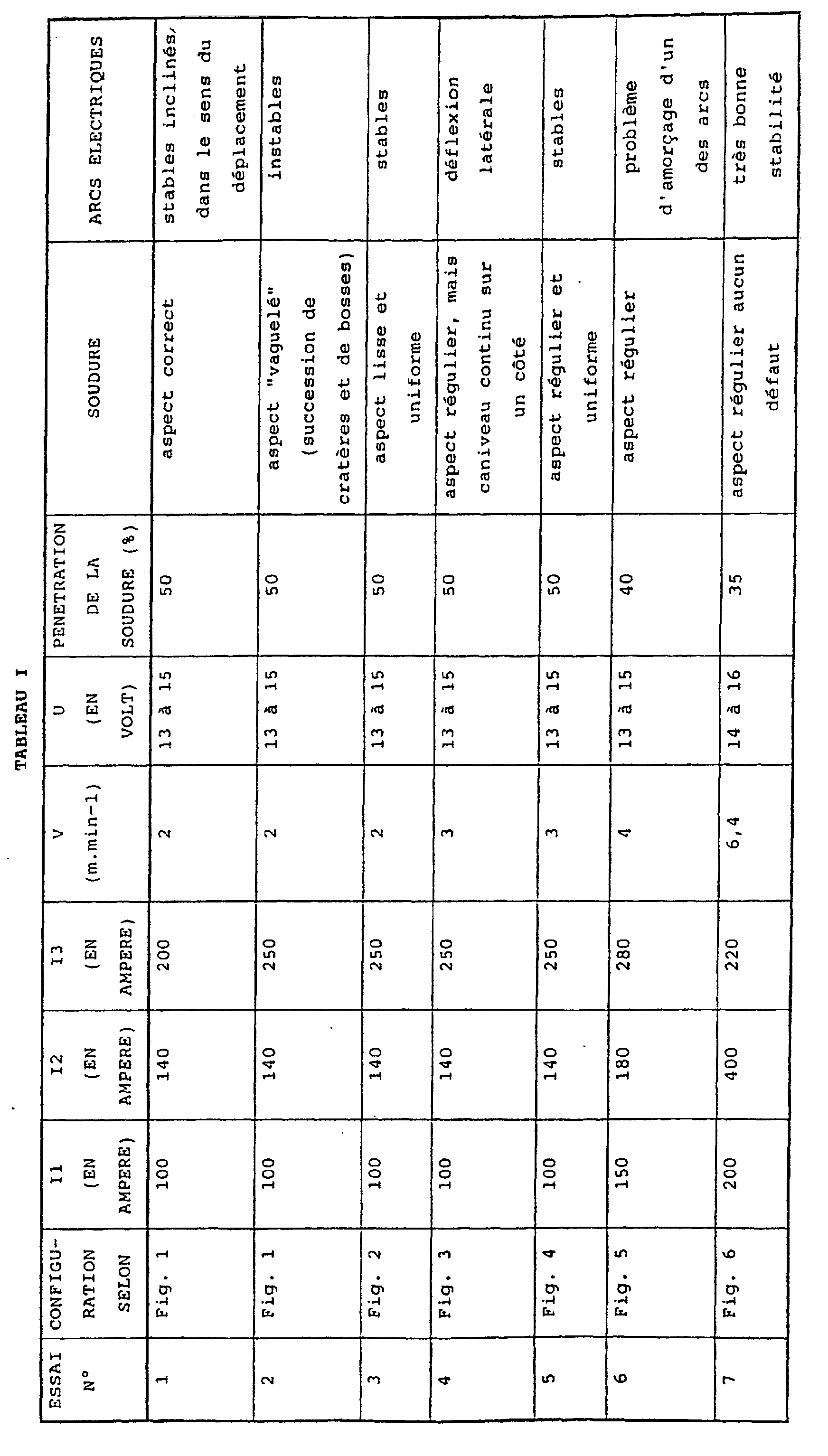
- Example 1 aims to study the influence of the position of the mass gain (s) (PMi) relative to to the electrodes (Ei) on the welding speed (V) and the appearance of the weld joint obtained.
- This example was made using a torch multi-cathode TIG welding with protective flux gaseous, the gas used being an Argon / Hydrogen mixture type Noxal 3 TM from Air Liquide and the torch work 3 electrodes (E1, E2, E3) spaced 25 mm apart.
- the gas used being an Argon / Hydrogen mixture type Noxal 3 TM from Air Liquide and the torch work 3 electrodes (E1, E2, E3) spaced 25 mm apart.
- a metal T tube is formed, continuous, successively in “U” (not shown), then in “O” by bringing together the 2 longitudinal edges BL and BL ' of a metallic sheet animated with a speed V of non-zero displacement along its longitudinal axis (arrow V in the figures).
- the 3 electrodes E1, E2 and E3 acting as cathodes are connected to the negative poles of generators welding (not shown) while the sockets masses PM1, PM2, PM2 'and PM3 are connected, as appropriate, to the positive poles of 3 generators GN1, GN2 and GN3, from so that the arcs can be established between the electrodes E1, E2 and E3 and the welding tube, which is connected to the positive poles of generators GN1 and GN2 and GN3 by means of said ground connections PM1, PM2, PM2 'and PM3 respectively.
- the number and the position mass gains vary.
- the weld S obtained is of variable appearance and penetration as a function of the operating conditions used, which are summarized in the following Tables I and II, in which I1, I2 and I3 are the intensities of the current through the electrodes E1, E2 and E3 respectively, V is the welding speed, and U is the welding voltage at the electrodes E1 to E3.
- test n ° 2 leads to an appearance weld bead poor and high instability of electric arcs.
- test 3 shows that one can remedy these problems by adopting the configuration shown in Figure 2, that is to say in retaining only one grounding PM3, which is located downstream of the electrodes E1 to E3; the cord of solder again becoming uniform and smooth.
- Test n ° 4 shows that when we increase the welding speed by adopting the configuration of the Figure 3, the other parameters remaining unchanged, we again, observe a lateral deflection of the arcs causing the appearance of the welding.
- FIG. 4 differs from Figure 3 only by the presence of an additional PM2 'earth connection symmetrical of the PM2 earth connection with respect to the tube.
- This problem can be remedied by controlling the paths taken by the currents to through the tube and minimizing the interactions between bows.
- test n ° 7 implements 3 electrodes E1 to E3 each associated with 3 earth connections PM1 to PM3, respectively.
- the flexibility of the electrical adjustments leads to an even better weld appearance, when e i is between + 7 and + 15 mm; this also makes it possible to very significantly increase the intensities used and therefore the welding speed while retaining very good arc stability and a flawless weld bead appearance.
- the distance e1 between the electrode E1 and the earth connection PM1 is about 9 mm
- the distance e2 is about 10 mm
- the distance e3 is of the order of 11 mm.
- test no. 8 was carried out using an octocathode torch, that is to say using 8 electrodes and 8 earth connections, each electrode being associated with a ground connection, so that the distance e i separating each electrode e i from each ground connection PM i is between - 5 and + 25 mm, or even between + 7 and + 15 mm.
- This test 8 confirms the observations of test no. 7, namely that an aspect weld is obtained regular and flawless, and arcs having very good stability and starting without problem, when the electrodes and their earth connections associated are positioned so that the distance ei is between - 5 and + 25 mm.
- the tube produced using the the invention must be filled with filling elements like powders, before being formed into an "O" then welded, or even subsequently rolled and / or drawn to a use diameter, performing a weld at full penetration of the two longitudinal edges of the metallic foil forming the tube may cause at least partial fusion of the filling elements it contains and / or contamination of the molten metal.
- Example 2 a tube containing powders of filling, i.e. a cored wire, 16.4 mm in diameter is welded on a small proportion of its thickness (penetration of around 40 to 50%) at means of a welding process using several electrodes, such as a multicathode TIG process analogous to those described in Example 1.
- the tube After welding, the tube is subjected to stages of rolling, drawing, recrystallization annealing and final drawing up to a diameter of 1.2 mm.
- Figures 7 and 8 show the cored wire obtained after welding and rolling up to a diameter of 12.7 mm ( Figure 7), and after drawing to a diameter of 1.2 mm (figure 8).
- this technique avoids any contamination of the weld by the contained powders in said tube and / or at least partial fusion of powders contained in the tube.
- This technique can also be applied to welding of an empty tube because it increases very significantly productivity, given that, any other thing being equal, the welding speed is a decreasing function of the desired penetration.
- the configuration of Figure 6 allows, for a torch tricathodes, to obtain a smooth appearance solder joint and regular and to overcome any deflection problem or "magnetic blowing".
- a torch hexacathodes electrodes E1 to E6
- an increase of the intensity on the tail electrodes increases the welding speed, but from a certain intensity value, it produces a blockage of the "liquid bath” upstream of these electrodes, which blockage of the "liquid bath” results by the formation of a metal bead upstream of the E6 electrode.
- This metal bead tends to reduce the distance separating the electrode from the molten metal liquid bath and can, when it gets bigger, short-circuit with the electrode and destroy it.
- the metal bead can go from periodically, under the electrode without destroying it, but, in this case, the appearance of the weld is found strongly altered by the presence of bumps irregular distributed over the entire length of the cord welding.
- Tests 9 to 12 recorded in table III below were made using a TIG torch hexacathodes with a spacing of about 25 mm between the different electrodes.
- the configuration adopted in this example 3 is analogous to FIG. 6, that is to say that the electrode E1 is the electrode located furthest upstream and the electrode E6 is that located furthest downstream, when the 'We consider the relative direction of movement of the wire (according to arrow V in Figure 6). TEST NO.
- I1, I2, I3, I4, I5 and I6 are the intensities of current flowing respectively through the electrodes E1 to E6.
- test # 12 although the energy overall implemented by the first 5 electrodes (E1 to E5), which is identical to that of test n ° 9, namely an overall intensity of 950 A, and that the intensity on the sixth electrode (E6) is higher in test no. 12 (200 A) that in test n ° 9 (170 A) there is no bead formation in trial # 12, unlike in test No. 9. This is explained by the fact that in test n ° 12, the molten metal had time to solidify during its path between the electrodes E4 and E6, the electrode E5 not being supplied with current.
- the highest temperature that can reach a molten material is the boiling point of the most volatile element of said material.
- the most volatile element is, in general, manganese whose boiling point is of the order of 2,060 ° C.
- the length of this source energy depends only on the welding speed, desired penetration and characteristics thermal effects of the material, such as diffusivity.
- Figures 9a and 9b and 10a and 10b confirm the need to provide an increasing spacing between the cathodes to ensure the attachment of the feet of each electric arc on solidified metal.
- the welding speed is 8 ms -1 and the tube to be welded is approximately 2.2 mm thick.
- Figures 10a and 10b are similar to Figures 9a and 9b, except that, in this case, the electrodes are no longer equidistant from each other other.
- the distance between the E1 electrode and E2 and that between the electrode E2 and E3 are equal to 25 mm, since, as we have seen previously, these are not above liquid metal bath.
- the penetration into the molten zone depends on the conduction heat from the tube surface inward of it, that is to say according to its thickness.
- the penetration decreases not only in relative value, that is to say as a percentage of the thickness but also in absolute value, i.e. for the same speed of welding and for the same welding intensities, the penetration is all the more effective as the thickness is weak.
- Figures 11 and 12 illustrate the penetration efficiency (in % and in mm, respectively) depending on the speed of welding of a heptacathode TIG process for two tubes of different thickness.
- Tests 13 to 16 recorded in Table IV below, aim to study the influence of a chamfering of longitudinal edges of the tube to be welded one with the other.
- the welding voltage is of the order of 14 to 16 v
- the welding speed is of the order of 6 m.min -1
- the tube to be welded to a thickness of about 2.5 mm.
- a chamfer at a height h or heel of between approximately 1/3 and about 2/3 the thickness of the metal foil to from which the tube is made.
- a welded tube over its entire thickness, that is to say substantially free from such a crack.
- a forge welding is possible between two parts when the temperature of said two parts is between about 1200 ° C and the melting temperature of said steel.
- Figure 13 presents a partial cross-sectional view of a tube manufactured by the method according to the invention.
- the weld joint is consisting of a darker first upper part fusion welded and a lower part welded by forging; the forge welding area being substantially the axis of symmetry of line 3.
Landscapes
- Engineering & Computer Science (AREA)
- Mechanical Engineering (AREA)
- Physics & Mathematics (AREA)
- Plasma & Fusion (AREA)
- Arc Welding In General (AREA)
- Butt Welding And Welding Of Specific Article (AREA)
- Metal Extraction Processes (AREA)
Description
L'invention se rapporte à un procédé et à un dispositif de fabrication de tubes métalliques soudés, lesdits tubes étant susceptibles de contenir un ou plusieurs éléments de remplissage, tels des poudres, des granulés ou leurs mélanges. Après soudage, les tubes obtenus peuvent être subséquemment laminés, tréfilés et/ou subir une cuisson intermédiaire, de sortes de leur conférer une forme compatible avec l'utilisation à laquelle ils sont destinés. Le procédé et le dispositif de l'invention peuvent être utilisés, notamment, pour fabriquer des fils fourrés destinés au soudage à l'arc électrique.The invention relates to a method and a device for manufacturing welded metal tubes, said tubes being capable of containing one or several filling elements, such as powders, granules or mixtures thereof. After welding, the tubes obtained can be subsequently rolled, drawn and / or undergo intermediate cooking, of their kind confer a form compatible with use to which they are intended for. The process and the device of the invention can be used, in particular, for manufacture cored wires for arc welding electric.
Habituellement, pour fabriquer un tube métallique, de manière industrielle et continue, on utilise une feuille métallique ou feuillard dont la largeur et l'épaisseur sont adaptés au tube que l'on veut produire, c'est-à-dire compatibles avec l'utilisation ultérieure dudit tube.Usually, to make a metal tube, industrially and continuously, we use a metal foil or strip whose width and the thickness are adapted to the tube that we want to produce, i.e. compatible with subsequent use of said tube.
Pour ce faire, la feuille métallique ou feuillard est placée sur un dispositif permettant d'animer ladite feuille métallique d'une vitesse de déplacement non nulle selon son axe longitudinal. Durant son déplacement, une succession de galets confère à ce feuillard, d'abord, une forme sensiblement en "U", puis une forme sensiblement en "O", par rapprochement des deux bords longitudinaux dudit feuillard, l'un vers l'autre, lesdits deux bords longitudinaux étant sensiblement rectilignes et parallèles l'un à l'autre.To do this, the metal sheet or strip is placed on a device allowing to animate said metallic sheet with a non-zero speed of movement along its longitudinal axis. During its displacement, a a succession of pebbles gives this strip, first, a substantially U-shaped, then a substantially U-shaped "O", by bringing together the two longitudinal edges of said strip, towards each other, said two edges longitudinal being substantially rectilinear and parallel to each other.
Lorsque le tube doit contenir des éléments de remplissage tels des poudres, des granulés ou leurs mélanges, ceux-ci sont introduits à l'intérieur du tube, lorsque celui-ci est en forme de "U".When the tube must contain elements of filling such as powders, granules or their mixtures, these are introduced inside the tube, when it is in the shape of a "U".
L'introduction des éléments de remplissage est réalisée au moyen d'un tapis sur lequel sont disposés les éléments de remplissage et lequel se déroule en synchronisme avec l'avance du feuillard, de sorte que les éléments de remplissage soient déversés, en continu, par le tapis à l'intérieur de la gouttière que forme le tube en "U". On ajuste la quantité d'éléments de remplissage déversée par le tapis, par réglage de la hauteur desdits éléments de remplissage sur ledit tapis.The introduction of the filling elements is made by means of a mat on which the filling elements and which takes place in synchronism with the advance of the strip, so that the filling elements are discharged, continuously, by the mat inside the gutter formed by the tube in "U". We adjust the quantity of filling elements dumped by the carpet, by adjusting the height of said filling elements on said mat.
Ensuite, comme précédemment, une nouvelle succession de galets permet de conférer au tube sa forme en "O", c'est-à-dire sa forme sensiblement cylindrique.Then, as before, a new succession of rollers gives the tube its "O" shape, that is to say its substantially cylindrical shape.
La réunion des deux bords longitudinaux du feuillard, lesquels se trouvent en regard l'un de l'autre, est généralement réalisée par soudage desdits bords l'un avec l'autre.The meeting of the two longitudinal edges of the strip, which are next to one of the other, is generally carried out by welding of said edges with each other.
Actuellement, au moins deux procédés de soudage sont utilisés industriellement, à savoir le procédé de soudage par haute fréquence et le procédé TIG multicathodes.Currently, at least two welding processes are used industrially, namely the welding process by high frequency and the multicathode TIG process.
Toutefois, ceux-ci présentent chacun un certain nombre d'inconvénients.However, these each have a certain number of drawbacks.
Ainsi, lorsque l'on met en oeuvre un procédé de soudage haute fréquence pour souder les bords longitudinaux d'un tube contenant des poudres non totalement amagnétiques, celles-ci sont "aspirées" sous l'effet du champ magnétique très intense créé par le courant de soudage haute fréquence et viennent alors contaminer la soudure, de sorte d'y provoquer des défauts engendrant une plus grande fragilité du joint soudé, lequel ne peut plus, dès lors, supporter sans rupture des transformations ultérieures, telles des étapes de tréfilages et/ou de laminage subséquentes.So, when we implement a method of high frequency welding to weld the edges longitudinal of a tube containing powders not completely non-magnetic, these are "sucked" under the effect of the very intense magnetic field created by the high frequency welding current and then come contaminate the weld so as to cause defects causing greater fragility of the welded joint, which can therefore no longer bear without breaking subsequent transformations, such as stages of subsequent drawing and / or rolling.
Les documents EP-A-0158691, EP-A-0158693, EP-A-0589470, US-A-4,584,169, US-A-4,632,882 et US-A-5,192,016 ont déjà soulignés ce problème et tentés d'apporter des solutions. Toutefois, aucune de ces solutions n'est réellement satisfaisante du point de vue industriel, car celles-ci imposent, notamment, de fortes contraintes quant aux poudres de remplissage à utiliser ou nécessitent des investissements très coûteux et très peu rentables.The documents EP-A-0158691, EP-A-0158693, EP-A-0589470, US-A-4,584,169, US-A-4,632,882 and US-A-5,192,016 have already highlighted this problem and attempted to provide solutions. However, none of these solutions is really satisfactory from an industrial point of view, because these impose, in particular, strong constraints as to the filling powders to be used or require very expensive investments and very little profitable.
Une alternative réside dans le procédé de soudage TIG multicathodes, lequel est utilisé pour la fabrication de tubes en matériau non ferromagnétique, tels les aciers inoxydables austénitiques ou les alliages cuivreux.An alternative is the welding process Multicathode TIG, which is used for manufacturing tubes made of non-ferromagnetic material, such as steels austenitic stainless steels or copper alloys.
En général, cette technique met en oeuvre trois électrodes alignées dans le sens du déplacement du tube et distantes l'une de l'autre d'une valeur constante que l'on cherche à réduire au minimum, mais qui dépend de l'encombrement des différents organes constitutifs, des impératifs d'isolement électrique des électrodes et de refroidissement de l'ensemble.In general, this technique implements three electrodes aligned in the direction of tube travel and distant from each other by a constant value that we seek to minimize, but that depends on the size of the various constituent organs, requirements for electrical insulation of the electrodes and cooling of the assembly.
Les vitesses de soudage en soudage TIG multicathodes sont, notamment, fonction de l'épaisseur du joint de soudure et de la nature du matériau, donc de la diffusivité thermique. Cependant, à géométrie similaire, lorsque les deux procédés peuvent être utilisés, le soudage haute fréquence peut être effectué à des vitesses très supérieures à celle du soudage TIG multicathodes.Welding speeds in multicathode TIG welding are, in particular, a function of the thickness of the joint of weld and the nature of the material, thermal diffusivity. However, with similar geometry, when both methods can be used, the high frequency welding can be done at speeds far superior to that of multicathode TIG welding.
En effet, en soudage haute fréquence, l'énergie est générée sur toute l'épaisseur des bords à souder l'un avec l'autre, alors qu'en soudage TIG multicathodes, l'énergie des arcs n'est transmise qu'à la surface des bords et doit ensuite diffuser selon l'épaisseur, de sorte que la face inférieure soit portée à une température supérieure à la température de fusion du matériau considéré.Indeed, in high frequency welding, the energy is generated over the entire thickness of the edges to be welded one with each other, while in multicathode TIG welding, the energy of the arcs is only transmitted to the surface of edges and must then diffuse according to the thickness, from so that the underside is brought to a temperature higher than the melting temperature of the material considered.
En d'autres termes, le procédé TIG multicathodes conduit à une productivité très inférieure à celle du soudage haute fréquence en pénalisant, par là même, son intérêt industriel.In other words, the multicathode TIG process leads to a productivity much lower than that of high frequency welding, thereby penalizing its industrial interest.
En outre, le procédé TIG multicathodes présente un inconvénient majeur à savoir le phénomène de "soufflage magnétique", lequel se traduit par des interactions non maítrisables des arcs électriques entre eux, lesquelles interactions obligent à limiter les intensités de courant mises en oeuvre dans chacune des électrodes et donc, en final, à réduire considérablement les vitesses de soudage.In addition, the multicathode TIG process presents a major drawback namely the phenomenon of "blowing magnetic ", which results in interactions not controllable electric arcs between them, which interactions require limiting current intensities implemented in each of the electrodes and therefore, in final, to significantly reduce the speeds of welding.
En effet, la pénétration d'une soudure, c'est-à-dire l'épaisseur de feuillard pouvant entrer en fusion de sorte de souder les deux bords l'un à l'autre, dépend notamment de l'intensité du courant mis en oeuvre dans le procédé TIG multicathodes et de la vitesse de soudage.Indeed, the penetration of a weld, that is to say the strip thickness that can melt kind of soldering the two edges to each other, depends in particular the intensity of the current used in the multicathode TIG process and welding speed.
Toute chose étant égales par ailleurs, la
pénétration d'une soudure est une fonction de l'énergie
de soudage (E) qui peut s'exprimer par la formule I
suivante:
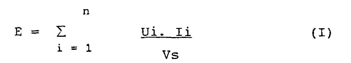
- Ui est la tension (en volt) de soudage de la cathode i;
- Ii est l'intensité (en ampère) du courant parcourant la cathode i;
- Vs est la vitesse de soudage (en cm.S-1);
- et n est le nombre (n ≥ 1) de cathode(s) i utilisée(s).
- Ui is the welding voltage (in volts) of cathode i;
- Ii is the intensity (in amperes) of the current flowing through cathode i;
- Vs is the welding speed (in cm.S -1 );
- and n is the number (n ≥ 1) of cathode (s) i used.
L'énergie de soudage E s'exprime alors en J.cm-1.The welding energy E is then expressed in J.cm -1 .
De là, on comprend que si l'on veut augmenter la vitesse de soudage tout en conservant la même pénétration, il est nécessaire d'augmenter l'énergie de soudage, c'est-à-dire la puissance délivrée par le ou les générateurs en augmentant l'intensité et/ou la tension sur l'une ou plusieurs des cathodes.From there, we understand that if we want to increase the welding speed while maintaining the same penetration it is necessary to increase the energy of welding, i.e. the power delivered by the generators by increasing the intensity and / or the voltage on one or more of the cathodes.
Cependant, en pratique, il est difficile de tirer parti de manière significative d'une augmentation de tension car, en procédé de soudage TIG multicathodes, la tension est une fonction croissante de la hauteur d'arc.However, in practice, it is difficult to draw started significantly from an increase in voltage because, in multicathode TIG welding process, the voltage is an increasing function of the arc height.
Or, une grande hauteur d'arc n'est pas favorable au soudage à grande vitesse. En effet, une grande hauteur d'arc engendre une diminution de la densité de puissance de l'arc à la surface de la pièce à souder, ce qui a pour effet, toute chose étant égale par ailleurs, d'élargir le cordon de soudure et donc de diminuer la pénétration, ce qui va à l'encontre de l'objectif recherché.However, a large arc height is not favorable to high speed welding. Indeed a great height arc causes a decrease in power density of the arc on the surface of the workpiece, which indeed, all else being equal, to expand the weld bead and therefore decrease penetration, this which goes against the objective sought.
En outre, un arc plus long est d'une part, plus sensible aux interactions magnétiques engendrant une déflexion de celui-ci et, d'autre part, a tendance à s'accrocher plus facilement et pendant un temps plus long au point chaud, c'est-à-dire au métal en fusion, d'où il résulte d'abord un allongement et un infléchissement de l'arc, puis un décrochage brutal de celui-ci lorsque la tache anodique, c'est-à-dire la racine de l'arc, vient se repositionner à la verticale de la cathode. On obtient alors une soudure discontinue caractéristique d'une trop grande vitesse de soudage.In addition, a longer arc is on the one hand, more sensitive to magnetic interactions generating a deflection of it and, on the other hand, tends to hang more easily and for a longer time hot spot, i.e. molten metal, where it first results from an elongation and a deflection of the arc and then a brutal stall of it when the anodic spot, that is to say the root of the arc, comes reposition the cathode vertically. We obtain then a discontinuous weld characteristic of too much high welding speed.
Il en résulte que l'augmentation de la puissance de l'arc électrique, nécessaire au maintien de la pénétration ne peut résulter que d'une augmentation de l'intensité.As a result, the increase in the power of the electric arc, necessary to maintain the penetration can only result from an increase in intensity.
Or, lorsque l'on augmente significativement l'intensité, sur l'une ou plusieurs des cathodes mises en oeuvre, on observe une instabilité accrue des arcs électriques et une formation d'un cordon de soudure très "vaguelé", c'est-à-dire une succession de cratères et de bosses à la surface du cordon de soudure.However, when we increase significantly the intensity, on one or more of the cathodes placed work, we observe an increased instability of the arcs electrical and a very welded bead formation "vaguelé", that is to say a succession of craters and bumps on the surface of the weld bead.
Ce phénomène est appelé "soufflage magnétique".This phenomenon is called "magnetic blowing".
On comprend aisément qu'un tel cordon de soudage "vaguelé" n'est pas apte à permettre un laminage et/ou un tréfilage subséquent exempt de problème de rupture.It is easy to understand that such a welding bead "vaguely" is not capable of allowing rolling and / or subsequent drawing free of breakage problem.
Par ailleurs, d'autres problèmes surviennent lorsque le tube à souder est préalablement rempli d'éléments de remplissage, par exemple des poudre métalliques.In addition, other problems arise when the tube to be welded is previously filled with filling, for example metallic powder.
Dans ce cas, l'exécution d'une soudure à pleine pénétration au moyen d'un procédé TIG multicathodes engendre de manière plus ou moins aléatoire, une fusion partielle desdits éléments de remplissage qu'il contient et/ou une contamination du métal fondu qui ne doit normalement résulter que de la fusion du feuillard.In this case, performing a full weld penetration using a multicathode TIG process more or less randomly, a fusion partial of said filling elements it contains and / or contamination of the molten metal which must not normally result only from the fusion of the strip.
Il s'en suit que le tube ne peut plus être laminé et/ou tréfilé sans que cette opération ne provoque une ou des ruptures étant donné que:
- la contamination du métal fondu par les éléments de remplissage conduit à la formation de défauts ou pour le moins d'un alliage dur, fragile et impossible à déformer sans provoquer de fissures, lesquelles sont autant d'amorces pour une rupture ultérieure du tube;
- la fusion partielle des éléments de remplissage à l'intérieur du tube donne naissance, après solidification, à de grosses particules indéformables qui blessent le tube jusqu'à provoquer sa rupture lorsqu'au cours d'un laminage ou d'un tréfilage ultérieur, le diamètre intérieur dudit tube devient de l'ordre de grandeur de la dimension des particules résultant de la fusion; et
- la volatilisation d'éléments de remplissage internes au tube provoque l'expulsion vers l'extérieur d'une partie de la soudure en fusion du fait de l'augmentation de la pression interne du tube.
- contamination of the molten metal by the filling elements leads to the formation of defects or at least of a hard alloy, fragile and impossible to deform without causing cracks, which are all primers for a subsequent rupture of the tube;
- the partial melting of the filling elements inside the tube gives rise, after solidification, to large non-deformable particles which injure the tube to the point of causing it to rupture when, during rolling or subsequent drawing, the inside diameter of said tube becomes of the order of magnitude of the dimension of the particles resulting from the fusion; and
- the volatilization of filling elements internal to the tube causes the expulsion towards the outside of part of the molten weld due to the increase in the internal pressure of the tube.
Le document US-A-4,396,820 propose une première solution pour lutter contre ce phénomène, à savoir de procéder à un soyage de l'un des bords à assembler afin de permettre un soudage du tube sur toute son épaisseur sans que le métal en fusion puisse venir au contact des éléments de remplissage contenus dans le tube.Document US-A-4,396,820 proposes a first solution to combat this phenomenon, namely to proceed to a crimping of one of the edges to be assembled in order allow welding of the tube over its entire thickness without the molten metal coming into contact with filling elements contained in the tube.
Toutefois, ce procédé présente l'inconvénient de compliquer l'opération de formage, de réduire le volume "libre" à l'intérieur du tube et d'altérer la symétrie axiale du tube.However, this method has the disadvantage of complicate the forming operation, reduce the volume "free" inside the tube and alter the symmetry axial of the tube.
Une autre solution consisterait à effectuer des soudures à pénétration partielle, c'est-à-dire à ne provoquer qu'une fusion d'une partie de l'épaisseur du feuillard au niveau des deux bords longitudinaux devant être soudés l'un à l'autre. Cependant, les soudures à pénétration partielle sont unanimement proscrites par l'homme du métier car la partie du plan de joint non soudé constitue une entaille sous la racine du cordon de soudure, laquelle est réputée se propager lors de toute réduction de la section du tube imposée par une étape de tréfilage ou de laminage subséquente.Another solution would be to perform partial penetration welds, i.e. not cause that a fusion of part of the thickness of the strip at the two longitudinal edges in front be welded to each other. However, the welds to partial penetration are unanimously prohibited by the skilled person because the part of the joint plane not soldered constitutes a notch under the root of the bead which is known to spread during any reduction of the section of the tube imposed by a step of subsequent drawing or rolling.
Par ailleurs, le document JP-A-59113996, considéré comme l'art antérieur le plus proche, enseigne un procédé de soudage monocathode pour souder les bords longitudinaux d'un tube, dans lequel une prise de masse en forme de roue vient appuyer sous le tube de manière à répartir le courant de soudage de part et d'autre du joint, entre l'électrode et la prise de masse. Ce procédé ne comprenant qu'une seule électrode est cependant limité en vitesse.Furthermore, document JP-A-59113996, considered to be the closest prior art, teaches a welding process monocathode for welding the longitudinal edges of a tube, in which a ground connection in wheel shape presses under the tube so as to distribute the welding current on both sides and on the other side of the joint, between the electrode and the earth connection. This process comprising only one electrode is however limited in speed.
Le but de la présente invention est donc de proposer un procédé et un dispositif de fabrication de tubes métalliques ne présentant pas les inconvénients de l'art antérieur.The aim of the present invention is therefore to propose a method and a device for manufacturing tubes metallic without the drawbacks of art prior.
L'invention concerne alors un procédé de fabrication
d'un tube métallique formé à partir d'une feuille
métallique ayant deux bords longitudinaux sensiblement
rectilignes et parallèles, dans lequel on soude, l'un
avec l'autre, les deux bords longitudinaux de la feuille
métallique au moyen d'un procédé de soudage mettant en
oeuvre au moins un arc électrique entre au moins trois
électrodes (Ei) et ladite feuille métallique au contact
d'au moins trois prises de masses (PMi),
dans lequel le plan de chaque prise de masse (PMi)
est positionnée à une distance (ei) comprise entre -5 mm
et +25 mm par rapport au plan de chaque électrode (Ei)
correspondante, le sens positif étant le sens de
déplacement relatif de la feuille métallique par rapport aux
électrodes (Ei).The invention therefore relates to a method of manufacturing a metal tube formed from a metal sheet having two substantially straight and parallel longitudinal edges, in which the two longitudinal edges of the metallic sheet by means of a welding process using at least one electric arc between at least three electrodes (Ei) and said metallic sheet in contact with at least three earth connections (PMi),
in which the plane of each ground connection (PMi) is positioned at a distance (e i ) of between -5 mm and +25 mm relative to the plane of each corresponding electrode (Ei), the positive direction being the direction of movement relative of the metal sheet with respect to the electrodes (Ei).
Dans le cadre de la présente invention, on appelle distance (ei) entre le plan de l'électrode et le plan de prise de masse, la distance séparant le plan passant par l'extrémité de chaque électrode (Ei) et perpendiculaire au tube du plan passant par l'extrémité de chaque prise de masse (PMi) correspondante et perpendiculaire audit tube; les plans (PEi) et (PPMi) sont donc parallèles l'un à l'autre.In the context of the present invention, distance (ei) between the plane of the electrode and the plane of ground gain, the distance between the plane passing through the end of each electrode (Ei) and perpendicular to the plane tube passing through the end of each socket of mass (PMi) corresponding and perpendicular to said tube; the planes (PEi) and (PPMi) are therefore parallel one to the other.
Selon le cas, le procédé de l'invention comprend l'une ou plusieurs des caractéristiques suivantes:
- la distance (ei) plan électrode/plan prise de masse est comprise entré 0 mm et +20 mm et, de préférence, entre +7 mm et +15 mm;
- on règle les écartements entre les électrodes afin d'assurer l'accrochage du pied de chaque arc électrique sur du métal solidifié;
- l'écartement entré une électrode (E1) et une électrode (E2) successives est inférieur ou égale à l'écartement entre une électrode (E2) et une électrode (E3) successives;
- l'intensité du courant parcourant une électrode est supérieure ou égale à 50 A et, de préférence, supérieure ou égale à 100 A;
- la vitesse relative de déplacement de la feuille est supérieure ou égale à 2 m.s-1, de préférence supérieure ou égale à 5 m.s-1;
- il comporte, en outre, une étape de chanfreinage d'au moins une partie des deux bords longitudinaux de la feuille métallique, de sorte de présenter avant soudage, un chanfrein en "V" ayant un angle d'ouverture (α) compris entre environ 30° et environ 120°, de préférence entre environ 60° et environ 90°;
- ledit chanfrein a une hauteur comprise
entre environ 1/3et environ 2/3 de l'épaisseur de la feuille métallique; - la feuille métallique est remplie d'au moins un élément de remplissage, préalablement à son soudage;
- on réalise une soudure incomplète des deux bords
longitudinaux de ladite feuille métallique, l'un avec
l'autre, par fusion partielle d'environ 20% à
environ 80% de l'épaisseur de ladite feuille au niveau desdits bords et, de préférence, d'environ 40% àenviron 60%; - on réalise, en outre, une soudure de forge desdits bords, l'un avec l'autre, par application d'une pression mécanique latérale sur au moins une partie de la paroi externe de la feuille, de sorte d'obtenir une soudure sensiblement complète selon toute l'épaisseur;
- après soudage, le tube subit au moins une étape de tréfilage, de laminage et/ou recuit de recristallisation.
- the distance (ei) of the electrode plane / grounded plane is between 0 mm and +20 mm and, preferably, between +7 mm and +15 mm;
- the distances between the electrodes are adjusted in order to ensure the attachment of the base of each electric arc to solidified metal;
- the spacing between a successive electrode (E 1 ) and an electrode (E 2 ) is less than or equal to the spacing between a successive electrode (E2) and an electrode (E 3 );
- the intensity of the current flowing through an electrode is greater than or equal to 50 A and, preferably, greater than or equal to 100 A;
- the relative speed of movement of the sheet is greater than or equal to 2 ms -1 , preferably greater than or equal to 5 ms -1 ;
- it further comprises a chamfering step of at least part of the two longitudinal edges of the metal sheet, so as to present before welding, a "V" chamfer having an opening angle (α) of between approximately 30 ° and about 120 °, preferably between about 60 ° and about 90 °;
- said chamfer has a height of between about 1/3 and about 2/3 of the thickness of the metal sheet;
- the metal sheet is filled with at least one filling element, prior to welding;
- an incomplete weld of the two longitudinal edges of said metal sheet is made, with each other, by partial fusion of approximately 20% to approximately 80% of the thickness of said sheet at the level of said edges and, preferably, from about 40% to about 60%;
- one carries out, in addition, a forge weld of said edges, one with the other, by application of a lateral mechanical pressure on at least a part of the external wall of the sheet, so as to obtain a weld substantially complete according to all the thickness;
- after welding, the tube undergoes at least one drawing, rolling and / or recrystallization annealing step.
L'invention concerne également un dispositif de fabrication d'un tube métallique à partir d'une feuille métallique ayant deux bords longitudinaux sensiblement rectilignes et parallèles, comportant des moyens de soudage à l'arc électrique pour souder, l'un avec l'autre, les deux bords longitudinaux de la feuille métallique mettant en oeuvre au moins trois électrodes (Ei) et au moins trois prises de masses (PMi) correspondantes, chaque prise de masse (PMi) étant positionnée à une distance (ei) comprise entre -5 mm et +25 mm par rapport à chaque électrode (Ei), le sens positif étant le sens de déplacement relatif de la feuille métallique par rapport aux électrodes (Ei). The invention also relates to a device for manufacturing a metal tube from a metal sheet having two substantially straight and parallel longitudinal edges, comprising arc welding means for welding, with each other , the two longitudinal edges of the metal sheet using at least three electrodes (Ei) and at least three corresponding ground connections (PMi), each ground connection (PMi) being positioned at a distance (e i ) between - 5 mm and +25 mm relative to each electrode (Ei), the positive direction being the direction of relative movement of the metal sheet with respect to the electrodes (Ei).
L'invention va maintenant être décrite plus en détail à l'aide d'exemples donnés à titre illustratif, mais non limitatif et en référence aux figures annexées.The invention will now be described in more detail. detail using examples given by way of illustration, but not limiting and with reference to the appended figures.
L'exemple 1 vise à étudier l'influence de la position de la ou des prises de masses (PMi) par rapport aux électrodes (Ei) sur la vitesse (V) de soudage et l'aspect du joint de soudure obtenu.Example 1 aims to study the influence of the position of the mass gain (s) (PMi) relative to to the electrodes (Ei) on the welding speed (V) and the appearance of the weld joint obtained.
Cet exemple a été réalisé à l'aide d'une torche de
soudage TIG multi-cathodes avec flux de protection
gazeux, le gaz utilisé étant un mélange Argon/Hydrogène
type Noxal 3™ de Air Liquide et la torche mettant en
oeuvre 3 électrodes (E1, E2, E3) espacées de 25 mm.This example was made using a torch
multi-cathode TIG welding with protective flux
gaseous, the gas used being an Argon / Hydrogen
Plus précisément, et ainsi que schématisé sur les figures 1 à 6, un tube T métallique est formé, en continu, successivement en "U" (non représenté), puis en "O" par rapprochement des 2 bords longitudinaux BL et BL' d'une feuille métallique animée d'une vitesse V de déplacement non nulle selon son axe longitudinal (flèche V sur les figures).More specifically, and as shown schematically on the Figures 1 to 6, a metal T tube is formed, continuous, successively in "U" (not shown), then in "O" by bringing together the 2 longitudinal edges BL and BL ' of a metallic sheet animated with a speed V of non-zero displacement along its longitudinal axis (arrow V in the figures).
Les 3 électrodes E1, E2 et E3 agissant comme cathodes sont reliées aux pôles négatifs de générateurs de soudage (non représenté) alors que les prises de masses PM1, PM2, PM2' et PM3 sont reliées, selon le cas, aux pôles positifs de 3 générateurs GN1, GN2 et GN3, de sorte que les arcs électriques puissent s'établir entre les électrodes E1, E2 et E3 et le tube à souder, lequel est relié aux pôles positifs des générateurs GN1 et GN2 et GN3 par l'intermédiaire desdites prises de masses PM1, PM2, PM2' et PM3 respectivement.The 3 electrodes E1, E2 and E3 acting as cathodes are connected to the negative poles of generators welding (not shown) while the sockets masses PM1, PM2, PM2 'and PM3 are connected, as appropriate, to the positive poles of 3 generators GN1, GN2 and GN3, from so that the arcs can be established between the electrodes E1, E2 and E3 and the welding tube, which is connected to the positive poles of generators GN1 and GN2 and GN3 by means of said ground connections PM1, PM2, PM2 'and PM3 respectively.
Selon la figure considérée, le nombre et la position des prises de masses varient.According to the figure considered, the number and the position mass gains vary.
Le plan de joint PJ de soudure résultant du rapprochement des 2 bords longitudinaux BL et BL' de la feuille métallique, l'un vers l'autre, par exemple de par l'action mécanique à la surface du tube T à souder de galets d'entraínement et de pressage (G1, G2, G3, G1', G2', G3'), est soumis à une opération de soudage par action simultanée de 3 arcs électriques (non représentés) jaillissant entre les électrodes E1 à E3 et le tube T.The PJ weld joint plane resulting from approximation of the two longitudinal edges BL and BL 'of the metal foil, one towards the other, for example by the mechanical action on the surface of the tube T to be welded drive and pressing rollers (G1, G2, G3, G1 ', G2 ', G3'), is subjected to a welding operation by simultaneous action of 3 electric arcs (not shown) gushing between the electrodes E1 to E3 and the tube T.
La soudure S obtenue est d'aspect et de pénétration
variables en fonction des conditions opératoires mises en
oeuvre, lesquelles sont résumées dans les tableaux I et
II suivants, dans lesquels I1, I2 et I3 sont les
intensités du courant à travers les électrodes E1, E2 et
E3 respectivement, V est la vitesse de soudage, et U est
la tension de soudage aux électrodes E1 à E3.
Il apparaít donc clairement au vu du tableau I précédent, que le trajet suivi par le courant à travers le tube en cours de fabrication a une incidence directe non seulement sur l'aspect du cordon de soudure, mais aussi sur la stabilité des arcs électriques; cette incidence étant d'autant plus marquée que les intensités mises en oeuvre sont élevées.It therefore appears clearly in the light of Table I previous, that the path followed by the current through the tube being manufactured has a direct impact not only on the appearance of the weld bead, but also on the stability of electric arcs; this incidence being all the more marked as the intensities implementations are high.
Ainsi, bien que les essais n° 1 et n° 2 ne se
différencient que par la valeur de l'intensité I3,
l'essai n° 2 conduit à un cordon de soudage d'aspect
médiocre et à une forte instabilité des arcs électriques.Thus, although
Toutefois, l'essai n° 3 montre que l'on peut
remédier à ces problèmes en adoptant la configuration
représentée sur la figure 2, c'est-à-dire en ne
conservant qu'une seule prise de masse PM3, laquelle est
située en aval des électrodes E1 à E3; le cordon de
soudure redevenant d'aspect uniforme et lisse.However,
L'essai n°4 montre que lorsque l'on augmente la vitesse de soudage en adoptant la configuration de la figure 3, les autres paramètres restant inchangés, on observe, là encore, une déflexion latérale des arcs électriques conduisant à une dégradation de l'aspect de la soudure.Test n ° 4 shows that when we increase the welding speed by adopting the configuration of the Figure 3, the other parameters remaining unchanged, we again, observe a lateral deflection of the arcs causing the appearance of the welding.
Néanmoins, il est possible de remédier à ces problèmes en adoptant la configuration de la figure 4, laquelle se différencie de la figure 3 uniquement par la présence d'une prise de masse PM2' supplémentaire symétrique de la prise de masse PM2 par rapport au tube.However, it is possible to remedy these problems by adopting the configuration of FIG. 4, which differs from Figure 3 only by the presence of an additional PM2 'earth connection symmetrical of the PM2 earth connection with respect to the tube.
Il ressort de ces différents essais qu'adopter une configuration symétrique tant géométrique qu'électrique, par rapport au plan dans lequel sont situées les électrodes permet d'obtenir une grande souplesse de réglage et d'augmenter les intensités du courant à travers les cathodes, donc la vitesse de soudage et ce, pour une pénétration donnée et sans problème de "soufflage magnétique" des arcs électriques, c'est-à-dire de déflexion latérale de ceux-ci.It appears from these various tests that adopting a symmetrical configuration both geometric and electric, relative to the plane in which the electrodes provides great flexibility setting and increasing the current intensities to through the cathodes, so the welding speed and this, for a given penetration and without problem of "magnetic blowing" of electric arcs, ie lateral deflection of these.
Il résulte de ces essais que, pour obtenir une soudure d'aspect correct et des arcs électriques stables, il est nécessaire de positionner la ou les prises de masses sur la génératrice du tube opposé au plan de soudure.It follows from these tests that, to obtain a correct appearance welding and stable electric arcs, it is necessary to position the socket (s) masses on the generatrix of the tube opposite the plane of welding.
Toutefois, cette condition n'est pas suffisante à elle seule.However, this condition is not sufficient to she alone.
En effet, il a été observé, par ailleurs, que si l'on dispose une prise de masse à l'intérieur de l'espace séparant la première de la dernière électrode, la souplesse des réglages, la stabilité des arcs électriques et la régularité des cordons de soudure sont moins bonnes que si la prise de masse est positionnée à l'aplomb de la dernière électrode ou légèrement au-delà, ainsi que représenté sur la figure 5 et en adoptant les paramètres de l'essai n° 6.Indeed, it has been observed, moreover, that if we have a ground connection inside the space separating the first from the last electrode, the flexibility of adjustments, stability of electric arcs and the regularity of the weld beads are less good only if the mass gain is positioned directly above the last electrode or slightly beyond, as well as shown in Figure 5 and adopting the parameters of test n ° 6.
Toutefois, si l'essai n° 6 a permis d'obtenir un
cordon de soudure d'aspect satisfaisant, il a été
observé, en outre, des difficultés d'amorçage de
l'électrode centrale.However, if
Par ailleurs, l'existence d'une prise de masse unique conduit à ce que la somme des courants mis en oeuvre dans les diverses électrodes provoque un échauffement plus ou moins important et durable de la zone de contact mobile entre le tube qui se déplace et la prise de masse qui est fixe.In addition, the existence of a mass gain single leads to the sum of the currents put in work in the various electrodes causes a more or less significant and lasting heating of the movable contact area between the moving tube and the grounding which is fixed.
Il est possible de remédier à ce problème en contrôlant les chemins empruntés par les courants à travers le tube et en minimisant les interactions entre les arcs.This problem can be remedied by controlling the paths taken by the currents to through the tube and minimizing the interactions between bows.
Ceci peut être réalisé au moyen d'un système
multimasses, c'est-à-dire mettant en oeuvre plusieurs
prises de masse isolées les unes des autres et
positionnées chacune en regard de l'électrode à laquelle
elle correspond, ainsi que représenté sur la figure 6 et
expérimenté dans l'essai n° 7.This can be achieved by means of a system
multi-mass, that is to say using several
ground connections isolated from each other and
each positioned opposite the electrode at which
it corresponds, as shown in Figure 6 and
experienced in
Plus précisément, l'essai n° 7 met en oeuvre 3
électrodes E1 à E3 associées chacune à 3 prises de masses
PM1 à PM3, respectivement.More specifically, test n ° 7
Si l'on appelle ei la distance séparant la verticale de l'électrode Ei de la position de la prise de masse PMi (avec i = 1,2 ou 3), ainsi que représenté sur la figure 6, on constate que les problèmes d'amorçage d'arcs électriques disparaissent totalement lorsque la distance ei est comprise entre - 5 et + 25 mm, le sens positif étant le sens de déplacement relatif du tube par rapport aux éléments, tel que donné par la flèche v.If we call e i the distance separating the vertical of the electrode E i from the position of the earth connection PM i (with i = 1,2 or 3), as shown in FIG. 6, we note that the arcing problems arises completely when the distance e i is between - 5 and + 25 mm, the positive direction being the direction of relative displacement of the tube with respect to the elements, as given by the arrow v.
De préférence, la souplesse des réglages électriques conduit à un aspect de soudure encore meilleur, lorsque ei est compris entre + 7 et + 15 mm; ceci permet en outre d'augmenter très sensiblement les intensités mises en oeuvre et donc la vitesse de soudage tout en conservant une très bonne stabilité d'arc électrique et un aspect de cordon de soudage sans défaut.Preferably, the flexibility of the electrical adjustments leads to an even better weld appearance, when e i is between + 7 and + 15 mm; this also makes it possible to very significantly increase the intensities used and therefore the welding speed while retaining very good arc stability and a flawless weld bead appearance.
A titre indicatif, sur la figure 6, la distance e1 entre l'électrode E1 et la prise de masse PM1 est de l'ordre de 9 mm, la distance e2 est de l'ordre de 10 mm et la distance e3 est de l'ordre de 11 mm.As an indication, in figure 6, the distance e1 between the electrode E1 and the earth connection PM1 is about 9 mm, the distance e2 is about 10 mm and the distance e3 is of the order of 11 mm.
Afin de vérifier l'essai n° 7, un essai n° 8 a été réalisé au moyen d'une torche octocathode, c'est-à-dire mettant en oeuvre 8 électrodes et 8 prises de masses, chaque électrode étant associée à une prise de masse, de sorte que la distance ei séparant chaque électrode ei de chaque prise de masse PMi est comprise entre - 5 et + 25 mm, voire entre + 7 et + 15 mm.In order to verify test no. 7, a test no. 8 was carried out using an octocathode torch, that is to say using 8 electrodes and 8 earth connections, each electrode being associated with a ground connection, so that the distance e i separating each electrode e i from each ground connection PM i is between - 5 and + 25 mm, or even between + 7 and + 15 mm.
Dans cet exemple 8 la configuration adoptée est
analogue à la configuration de la figure 6 et les
paramètres de soudage adoptés sont donnés dans le
tableau II ci-après.
(A)
(A)
(A)
(A)
(A)
(A)
(A)
(A)
(V)
m.min-1
(AT)
(AT)
(AT)
(AT)
(AT)
(AT)
(AT)
(AT)
(V)
m.min -1
Cet essai 8 confirme les observations de l'essai n° 7, à savoir que l'on obtient une soudure d'aspect régulier et sans défaut, et des arcs électriques ayant une très bonne stabilité et s'amorçant sans problème, lorsque les électrodes et leurs prises de masses associées sont positionnées de sorte que la distance ei soit comprise entre - 5 et + 25 mm.This test 8 confirms the observations of test no. 7, namely that an aspect weld is obtained regular and flawless, and arcs having very good stability and starting without problem, when the electrodes and their earth connections associated are positioned so that the distance ei is between - 5 and + 25 mm.
Lorsque le tube fabriqué au moyen du procédé de l'invention doit être rempli d'éléments de remplissage tels des poudres, avant d'être formé en "O" puis soudé, voire subséquemment laminé et/ou tréfilé jusqu'à un diamètre d'utilisation, l'exécution d'une soudure à pleine pénétration des deux bords longitudinaux de la feuille métallique formant le tube risque d'engendrer une fusion au moins partielle des éléments de remplissage qu'il contient et/ou une contamination du métal fondu.When the tube produced using the the invention must be filled with filling elements like powders, before being formed into an "O" then welded, or even subsequently rolled and / or drawn to a use diameter, performing a weld at full penetration of the two longitudinal edges of the metallic foil forming the tube may cause at least partial fusion of the filling elements it contains and / or contamination of the molten metal.
Afin de résoudre ce problème de fusion partielle des éléments de remplissage contenus dans un tel tube, tel un fil fourré, il peut être nécessaire de réaliser une soudure à pénétration partielle, c'est-à-dire selon une partie seulement de l'épaisseur de la paroi dudit tube.In order to solve this problem of partial merger of filling elements contained in such a tube, such as a cored wire, it may be necessary to make a partial penetration welding, i.e. according to a only part of the thickness of the wall of said tube.
Dans l'exemple 2, un tube contenant des poudres de remplissage, c'est-à-dire un fil fourré, de 16,4 mm de diamètre est soudé sur une faible proportion de son épaisseur (pénétration de l'ordre de 40 à 50% environ) au moyen d'un procédé de soudage mettant en oeuvre plusieurs électrodes, tel un procédé TIG multicathodes analogue à ceux décrits dans l'exemple 1.In Example 2, a tube containing powders of filling, i.e. a cored wire, 16.4 mm in diameter is welded on a small proportion of its thickness (penetration of around 40 to 50%) at means of a welding process using several electrodes, such as a multicathode TIG process analogous to those described in Example 1.
Après soudage, le tube est soumis à des étapes de laminage, tréfilage, recuit de recristallisation et tréfilage final jusqu'à un diamètre de 1,2 mm.After welding, the tube is subjected to stages of rolling, drawing, recrystallization annealing and final drawing up to a diameter of 1.2 mm.
Les figures 7 et 8 représentent le fil fourré obtenu après soudage et laminage jusqu'à un diamètre de 12,7 mm (figure 7), et après tréfilage jusqu'à un diamètre de 1,2 mm (figure 8).Figures 7 and 8 show the cored wire obtained after welding and rolling up to a diameter of 12.7 mm (Figure 7), and after drawing to a diameter of 1.2 mm (figure 8).
On constate, de manière surprenante, que les
différentes étapes de déformation dû fil (laminage,
tréfilage...) n'engendrent pas de propagation de la
fissure 1 que constitue la partie du plan de joint non
soudé.It is surprising to note that the
different stages of wire deformation (rolling,
wire drawing ...) do not cause propagation of the
En fait, le rapport initial entre la partie soudée 2
et non soudé 1, est conservé quelque soit le diamètre
d'observation, c'est-à-dire le diamètre du fil fourré
après déformation.In fact, the initial relationship between the welded
Il ressort de cet exemple 2 qu'il est possible de réduire par laminage et/ou tréfilage la section d'un tube soudé seulement sur une partie de son épaisseur et ce sans risquer une rupture dudit fil fourré par propagation de la fissure.It emerges from this example 2 that it is possible to reduce the cross-section of a tube by rolling and / or drawing welded only over part of its thickness and this without risk of breaking said cored wire by propagation from the crack.
En outre, cette technique permet d'éviter toute contamination de la soudure par les poudres contenues dans ledit tube et/ou une fusion au moins partielle des poudres contenues dans le tube.In addition, this technique avoids any contamination of the weld by the contained powders in said tube and / or at least partial fusion of powders contained in the tube.
Cette technique peut être également appliquée au soudage d'un tube vide car elle permet d'augmenter très significativement la productivité, étant donné que, toute chose étant égale par ailleurs, la vitesse de soudage est une fonction décroissante de la pénétration désirée. This technique can also be applied to welding of an empty tube because it increases very significantly productivity, given that, any other thing being equal, the welding speed is a decreasing function of the desired penetration.
Comme exposé dans l'exemple 1 précédent, la configuration de la figure 6 permet, pour une torche tricathodes, d'obtenir un joint de soudure d'aspect lisse et régulier et de pallier tout problème de déflexion ou "soufflage magnétique". Dans le cas d'une torche hexacathodes (électrodes E1 à E6), une augmentation de l'intensité sur les électrodes de queue (électrodes E4, E5 et/ou E6) permet d'augmenter la vitesse de soudage, mais à partir d'une certaine valeur d'intensité, il se produit un blocage du "bain liquide" en amont de ces électrodes, lequel blocage du "bain liquide" se traduit par la formation d'un bourrelet de métal en amont de l'électrode E6.As explained in Example 1 above, the configuration of Figure 6 allows, for a torch tricathodes, to obtain a smooth appearance solder joint and regular and to overcome any deflection problem or "magnetic blowing". In the case of a torch hexacathodes (electrodes E1 to E6), an increase of the intensity on the tail electrodes (E4 electrodes, E5 and / or E6) increases the welding speed, but from a certain intensity value, it produces a blockage of the "liquid bath" upstream of these electrodes, which blockage of the "liquid bath" results by the formation of a metal bead upstream of the E6 electrode.
Ce bourrelet de métal tend à réduire la distance séparant l'électrode du bain liquide de métal en fusion et peut, lorsqu'il grossit, entrer en court-circuit avec l'électrode et la détruire.This metal bead tends to reduce the distance separating the electrode from the molten metal liquid bath and can, when it gets bigger, short-circuit with the electrode and destroy it.
Parfois, le bourrelet de métal peut passer de manière périodique, sous l'électrode sans la détruire, mais, dans ce cas, l'aspect de la soudure s'en trouve fortement altéré de par la présence de bosses irrégulières distribuées sur toute la longueur du cordon de soudage.Sometimes the metal bead can go from periodically, under the electrode without destroying it, but, in this case, the appearance of the weld is found strongly altered by the presence of bumps irregular distributed over the entire length of the cord welding.
Une observation attentive du processus conduisant à la formation de ce bourrelet de métal montre que celui-ci apparaít lorsque l'un des arcs électriques attaque du métal fondu, c'est-à-dire du métal ayant été fondu par les électrodes situées en amont dudit arc et qui ne s'est pas encore solidifié.Careful observation of the process leading to the formation of this metal bead shows that it appears when one of the electric arcs attacks the molten metal, i.e. metal that has been melted by the electrodes located upstream of said arc and which have not not yet solidified.
Les essais 9 à 12 consignés dans le tableau III ci-après ont été réalisés au moyen d'une torche TIG hexacathodes présentant un écartement d'environ 25 mm entre les différentes électrodes. Tests 9 to 12 recorded in table III below were made using a TIG torch hexacathodes with a spacing of about 25 mm between the different electrodes.
La configuration adoptée dans cet exemple 3 est
analogue de la figure 6, c'est-à-dire que l'électrode E1
est l'électrode située le plus en amont et l'électrode E6
est celle située le plus en aval, lorsque l'on considère
le sens de déplacement relatif du fil (selon la flèche V
sur la figure 6).
(A)
(A)
(A)
(A)
(A)
(A)
(V)
(m.min-1)
(AT)
(AT)
(AT)
(AT)
(AT)
(AT)
(V)
(m.min -1 )
I1, I2, I3, I4, I5 et I6 sont les intensités de courant parcourant respectivement les électrodes E1 à E6.I1, I2, I3, I4, I5 and I6 are the intensities of current flowing respectively through the electrodes E1 to E6.
Dans les conditions de l'essai n° 9, on observe la formation d'un bourrelet de métal en amont de l'électrode E6.Under the conditions of test No. 9, the formation of a metal bead upstream of the electrode E6.
Toutefois, ainsi qu'il ressort de l'essai n°10, une diminution de l'intensité du courant traversant les électrodes E4 et E5, sans modification de l'intensité du courant sur l'électrode E6, conduit à une disparition de ce bourrelet de métal.However, as appears from test 10, a decrease in the intensity of the current flowing through electrodes E4 and E5, without changing the intensity of the current on the E6 electrode, leads to a disappearance of this metal bead.
Ceci peut s'expliquer par le fait que les électrodes E4 et E5 transmettent au tube une énergie moins importante dans l'essai 10 que dans l'essai 9, ce qui implique que le métal fondu à plus de temps pour se solidifier avant d'arriver à l'électrode E6, dans l'essai n° 10, de sorte que l'arc électrique généré par l'électrode E6 prend naissance sur du métal solidifié (essai 10) et non sur du métal fondu (essai 9).This can be explained by the fact that the electrodes E4 and E5 transmit less energy to the tube important in trial 10 than in trial 9, which implies that the molten metal takes longer to solidify before arriving at electrode E6, in the test # 10, so the electric arc generated by the E6 electrode originates on solidified metal (test 10) and not on molten metal (test 9).
Il ressort de l'essai n° 11 qu'une réduction de la vitesse de soudage, sans modification des autres paramètres électriques, provoquent une augmentation de l'énergie de soudage et, par conséquent, une diminution de la vitesse de refroidissement de la soudure avec apparition d'un bourrelet de métal devant l'électrode E6.It appears from test No. 11 that a reduction in the welding speed, without modification of the others electrical parameters, cause an increase in welding energy and therefore a decrease of the cooling rate of the weld with appearance of a metal bead in front of the E6 electrode.
En d'autres termes, contrairement à l'essai n°10, dans l'essai n° 11, la soudure est encore à l'état liquide en arrivant sous l'électrode E6 et l'arc électrique généré par l'électrode E6 prend donc naissance sur du métal en fusion, d'où formation d'un bourrelet de métal. Ces observations sont confirmées par l'essai n° 12.In other words, unlike test # 10, in test n ° 11, the weld is still in the state liquid arriving under the E6 electrode and the arc electric generated by the E6 electrode therefore takes birth on molten metal, resulting in the formation of a bead of metal. These observations are confirmed by test no. 12.
En effet, dans l'essai n° 12, bien que l'énergie globale mise en oeuvre par les 5 premières électrodes (E1 à E5), soit identique à celle de l'essai n° 9, à savoir une intensité globale de 950 A, et que l'intensité sur la sixième électrode (E6) soit plus élevée dans l'essai n° 12 (200 A) que dans l'essai n° 9 (170 A) il n'y a pas de formation de bourrelet dans l'essai n° 12, contrairement à l'essai n° 9. Ceci s'explique par le fait que dans l'essai n° 12, le métal en fusion a eu le temps de se solidifier durant son trajet entre les électrodes E4 et E6, l'électrode E5 n'étant pas alimentée en courant.Indeed, in test # 12, although the energy overall implemented by the first 5 electrodes (E1 to E5), which is identical to that of test n ° 9, namely an overall intensity of 950 A, and that the intensity on the sixth electrode (E6) is higher in test no. 12 (200 A) that in test n ° 9 (170 A) there is no bead formation in trial # 12, unlike in test No. 9. This is explained by the fact that in test n ° 12, the molten metal had time to solidify during its path between the electrodes E4 and E6, the electrode E5 not being supplied with current.
Il ressort clairement des essais 9 à 12, que l'écartement entre les différentes électrodes ne doit pas uniquement être dicté par les contraintes d'isolement électrique, de refroidissement ou de mécanique pure, contrairement à la pratique usuelle , mais doit aussi prendre en compte un certain nombre de paramètre conduisant à une optimisation du procédé de soudage et par, là même, du procédé de fabrication du tube.It is clear from tests 9 to 12 that the spacing between the different electrodes must not only be dictated by isolation constraints electrical, cooling or pure mechanical, contrary to usual practice, but must also take into account a certain number of parameters leading to an optimization of the welding process and by there, the tube manufacturing process.
En effet, en soudage TIG, une partie de l'énergie de l'arc électrique est transférée à la surface de la pièce à souder. Si l'on néglige les mouvements du bain liquide dont les origines sont diverses, mais dont la principale est l'effet Marangoni, c'est-à-dire un mouvement lié au gradient de tension superficielle en fonction du gradient de température entre le centre et le bord de la zone fondue, la propagation de la chaleur dans l'épaisseur de la pièce à souder, ici le tube, se fait par conduction.Indeed, in TIG welding, part of the energy of the electric arc is transferred to the work surface welding. If we neglect the movements of the liquid bath whose origins are diverse, but the main one is the Marangoni effect, that is to say a movement linked to the surface tension gradient as a function of the gradient temperature between the center and the edge of the area melted, the spread of heat in the thickness of the part to be welded, here the tube, is done by conduction.
Donc, si l'on veut obtenir une pénétration donnée en soudant à une vitesse élevée, il faut maintenir la surface du cordon de soudure à la plus haute température possible et suffisamment longtemps pour que l'isotherme de fusion ait le temps d'atteindre la pénétration souhaitée.So, if we want to obtain a given penetration in welding at high speed, the weld bead surface at the highest temperature possible and long enough for the isotherm time to reach penetration desired.
Or, la température la plus élevée que peut atteindre un matériau en fusion est la température d'ébullition de l'élément le plus volatil dudit matériau. Par exemple, dans le cas des aciers, l'élément le plus volatil est, en général, le manganèse dont la température d'ébullition est de l'ordre de 2 060°C.However, the highest temperature that can reach a molten material is the boiling point of the most volatile element of said material. For example, in the case of steels, the most volatile element is, in general, manganese whose boiling point is of the order of 2,060 ° C.
On voit alors que, pour optimiser le rendement énergétique d'un procédé de soudage qui procède par conduction simultanément à la vitesse d'exécution de la soudure, il faut avoir un apport énergétique continu, de sorte de maintenir la surface au voisinage de la température d'ébullition pendant un temps tel que l'isotherme "température de fusion" atteigne la profondeur, c'est-à-dire l'épaisseur, désirée. We then see that, to optimize the yield energy of a welding process which proceeds by conduction simultaneously with the speed of execution of the welding, you must have a continuous energy supply, kind of maintain the surface in the vicinity of the boiling point for a time such as the "melting temperature" isotherm reaches the depth, that is, the desired thickness.
En d'autres termes, il faut mettre en oeuvre une source d'énergie linéaire de forte puissance à son origine, de telle sorte que le métal soit rapidement porté à la température d'ébullition de l'élément le plus volatil, puis de puissance plus faible ensuite, étant donné qu'il suffit de compenser les pertes dues à la conduction et au rayonnement.In other words, you have to implement a high power linear power source at its origin, so that the metal is quickly brought to the boiling point of the highest element volatile, then of lower power then, being given that it is sufficient to compensate for the losses due to the conduction and radiation.
Il en résulte que la longueur de cette source d'énergie dépend uniquement de la vitesse de soudage, de la pénétration souhaitée et des caractéristiques thermiques du matériau, telle la diffusivité.As a result, the length of this source energy depends only on the welding speed, desired penetration and characteristics thermal effects of the material, such as diffusivity.
Dans le cas présent, c'est-à-dire en soudage mulitcathodes, il apparaít alors que:
- les intensités de courant les plus fortes doivent être concentrées sur les électrodes les plus en amont, de sorte de fournir l'énergie suffisante pour porter la surface du joint de soudure à haute température;
- le nombre d'électrodes devra être d'autant plus élevé que l'on souhaite souder rapidement;
- la distance entre les différentes électrodes doit être ajustée pour que le pied anodique des arcs électriques s'accroche sur du métal tout juste solidifié, de sorte d'éviter la formation des bourrelets précédemment décrits, tout en assurant un minimum de variations de température à la surface du joint de soudure;
- l'intensité du courant traversant les électrodes de queue, c'est-à-dire situées le plus en aval, devra être réglée pour apporter une énergie juste suffisante pour permettre d'élever la température de surface de matériau à souder jusqu'à la température d'ébullition de l'élément le plus volatil du joint de soudure.
- the highest current intensities must be concentrated on the most upstream electrodes, so as to supply sufficient energy to bring the surface of the solder joint to high temperature;
- the number of electrodes must be higher the faster you want to weld;
- the distance between the different electrodes must be adjusted so that the anode base of the electric arcs is attached to metal that has just solidified, so as to avoid the formation of the beads previously described, while ensuring a minimum of temperature variations at the solder joint surface;
- the intensity of the current passing through the tail electrodes, that is to say located furthest downstream, must be adjusted to provide energy just sufficient to allow the surface temperature of the material to be welded to be raised to the boiling temperature of the most volatile element in the solder joint.
Les figures 9a et 9b et 10a et 10b confirment la nécessité de prévoir un écartement croissant entre les cathodes afin d'assurer l'accrochage des pieds de chaque arc électrique sur du métal solidifié. Figures 9a and 9b and 10a and 10b confirm the need to provide an increasing spacing between the cathodes to ensure the attachment of the feet of each electric arc on solidified metal.
Plus précisément, les figures 9a et 9b représentent les isothermes à 2 000°C, à la température de fusion de 1 535°C (Tfus) et à 1 200°C, lesquelles ont été calculées à partir des équations de propagation de la chaleur et lesquelles ont été positionnées dans le plan correspondant soit à la surface du cordon, c'est-à-dire à une vue en coupe selon les axes X et Y avec Z = 0 (figure 9a), ou soit dans le plan perpendiculaire passant par l'axe dudit cordon, c'est-à-dire selon les axes X et Z avec Y=0 (figure 9b).More specifically, Figures 9a and 9b show isotherms at 2000 ° C, at the melting temperature of 1,535 ° C (Tfus) and 1,200 ° C, which have been calculated from the heat propagation equations and which have been positioned in the plane corresponding either to the surface of the cord, that is to say to a sectional view along the X and Y axes with Z = 0 (figure 9a), or either in the perpendicular plane passing through the axis of said cord, that is to say along the axes X and Z with Y = 0 (Figure 9b).
La torche utilisée pour obtenir le joint de soudure représenté sur les figures 9a et 9b est une torche hexacathode dont les électrodes E1 à E6 sont séparées les unes des autres d'une distance égale à environ 25 mm et sont parcourues respectivement par les courants suivants: I1= 350 A, I2 = 225 A, I3 = 200 A et I4=I5=I6= 250 A.The torch used to obtain the solder joint shown in Figures 9a and 9b is a torch hexacathode whose electrodes E1 to E6 are separated the from each other by a distance of approximately 25 mm and are traversed respectively by the following currents: I1 = 350 A, I2 = 225 A, I3 = 200 A and I4 = I5 = I6 = 250 A.
En outre, la vitesse de soudage est de 8 m.s-1 et le tube à souder a une épaisseur de 2.2 mm environ.In addition, the welding speed is 8 ms -1 and the tube to be welded is approximately 2.2 mm thick.
Il apparaít clairement sur les figures 9a et 9b que, dans ces conditions, les électrodes E5 et E6 sont situées au-dessus du bain de métal liquide formé par fusion au moins partielle des bords du tube à souder au moyen des électrodes E1 à E4 qui les précédent, ce qui implique la formation d'un bourrelet métallique à la surface du cordon de soudure, ainsi que susmentionné.It is clear from Figures 9a and 9b that, under these conditions, the electrodes E5 and E6 are located above the bath of liquid metal formed by fusion at less partial of the edges of the tube to be welded by means of electrodes E1 to E4 which precede them, which implies the formation of a metallic bead on the surface of the weld bead, as mentioned above.
Les figures 10a et 10b sont analogues aux figures 9a et 9b, à l'exception du fait que, dans ce cas, les électrodes ne sont plus équidistantes les unes des autres.Figures 10a and 10b are similar to Figures 9a and 9b, except that, in this case, the electrodes are no longer equidistant from each other other.
Plus précisément, la distance entre l'électrode E1 et E2 et celle entre l'électrode E2 et E3 sont égales à 25 mm, étant donné que, comme nous l'avons vu précédemment, celles-ci ne se trouvent pas au-dessus de bain de métal liquide. More specifically, the distance between the E1 electrode and E2 and that between the electrode E2 and E3 are equal to 25 mm, since, as we have seen previously, these are not above liquid metal bath.
Toutefois, la distance entre E3 et E4 a été portée à 30 mm, celle entre E4 et E5 à 40 mm et celle entre E5 et E6 à 45 mm.However, the distance between E3 and E4 has been increased to 30 mm, that between E4 and E5 at 40 mm and that between E5 and E6 to 45 mm.
Il apparaít clairement au vu des figures 10a et 10b, qu'augmenter les distances séparant les dernières électrodes (E4 à E6), tout en conservant les mêmes intensités de courant et la même vitesse de soudage, permet d'obtenir des isothermes de température de fusion distinctes pour chaque électrode, c'est-à-dire un amorçage des différents arcs électriques relatifs à chaque électrode sur du métal solidifié (figure 10a et 10b) et non plus sur du métal fondu (figure 9a et 9b).It is clear from the figures 10a and 10b, that increase the distances between the last electrodes (E4 to E6), while keeping the same current intensities and the same welding speed, allows to obtain isotherms of melting temperature separate for each electrode, i.e. a initiation of the various electric arcs relating to each electrode on solidified metal (Figure 10a and 10b) and no longer on molten metal (FIGS. 9a and 9b).
Comme nous l'avons vu dans l'exemple 3, lors de la mise en oeuvre d'un procédé de soudage multicathodes, la pénétration dans la zone fondue dépend de la conduction de la chaleur depuis la surface du tube vers l'intérieur de celui-ci, c'est-à-dire selon son épaisseur.As we saw in example 3, when implementation of a multicathode welding process, the penetration into the molten zone depends on the conduction heat from the tube surface inward of it, that is to say according to its thickness.
De là, lorsque l'on augmente l'épaisseur du tube, la pénétration décroít non seulement en valeur relative, c'est-à-dire en pourcentage de l'épaisseur mais aussi en valeur absolue, c'est-à-dire que pour une même vitesse de soudage et pour de mêmes intensités de soudage, la pénétration est d'autant plus efficace que l'épaisseur est faible.From there, when we increase the thickness of the tube, the penetration decreases not only in relative value, that is to say as a percentage of the thickness but also in absolute value, i.e. for the same speed of welding and for the same welding intensities, the penetration is all the more effective as the thickness is weak.
Ceci est d'ailleurs confirmé par les figures 11 et 12 lesquelles illustrent l'efficacité de pénétration (en % et en mm, respectivement) en fonction de la vitesse de soudage d'un procédé TIG heptacathode et ce, pour deux tubes d'épaisseur différente.This is moreover confirmed by Figures 11 and 12 which illustrate the penetration efficiency (in % and in mm, respectively) depending on the speed of welding of a heptacathode TIG process for two tubes of different thickness.
Plus précisément, les courbes C1 et C3 ont été obtenues avec un tube d'épaisseur 2,5 mm et les courbes C2 et C4 avec un tube d'épaisseur 2,2 mm; dans tous les cas, les intensités du courant traversant les différentes électrodes E1 à E7 sont respectivement les suivantes: I1 = 320 A, I2 = 300 A, I3 = I4 = I5 = I6 = I7 = 220 A.More precisely, curves C1 and C3 have been obtained with a 2.5 mm thick tube and the curves C2 and C4 with a 2.2 mm thick tube; in all the case, the intensities of the current flowing through the different electrodes E1 to E7 are respectively as follows: I1 = 320 A, I2 = 300 A, I3 = I4 = I5 = I6 = I7 = 220 A.
Les essais 13 à 16, consignés dans le tableau IV ci-après, visent à étudier l'influence d'un chanfreinage des bords longitudinaux du tube devant être soudés l'un avec l'autre.Tests 13 to 16, recorded in Table IV below, aim to study the influence of a chamfering of longitudinal edges of the tube to be welded one with the other.
Ces essais 13 à 16 ont été réalisés au moyen d'un procédé TIG hexacathodes, dont les électrodes E1 à E6 sont respectivement traversées par les courants suivants: I1 = 360 A, I2 = 320 A, I3 = 250 A, I4 = 220 A, I5 = 190 A et I6 = 180 A.These tests 13 to 16 were carried out using a hexacathode TIG process, including electrodes E1 to E6 are crossed respectively by the following currents: I1 = 360 A, I2 = 320 A, I3 = 250 A, I4 = 220 A, I5 = 190 A and I6 = 180 A.
En outre, la tension de soudage est de l'ordre de 14
à 16 v, la vitesse de soudage est de l'ordre de 6 m.min-1
et le tube à souder à une épaisseur d'environ 2.5 mm.
(en %)
(in %)
Il ressort clairement du tableau IV précédent qu'un chanfreinage des bords du tube permet d'augmenter la pénétration de la soudure.It is clear from the preceding table IV that chamfering the edges of the tube increases the weld penetration.
En d'autres termes, toute chose étant égale par ailleurs, on peut augmenter la pénétration ou pour une même pénétration augmenter la vitesse de soudage, en faisant en sorte que l'énergie apportée par les premières cathodes ne soit plus transférée à la surface du tube, mais partiellement au moins dans son épaisseur, ce qui peut être réalisé par le biais d'un chanfreinage avant soudage des bords du tube. In other words, everything being equal by elsewhere, we can increase penetration or for a same penetration increase the welding speed, ensuring that the energy provided by the first cathodes is no longer transferred to the surface of the tube, but partially at least in its thickness, which can be achieved by front chamfering welding of the edges of the tube.
On constate également, au vu du tableau IV, que pour une même hauteur de talon (1,3 mm), c'est-à-dire une même hauteur de bord non chanfreinée, l'efficacité de pénétration augmente proportionnellement à l'angle (α) d'ouverture du chanfrein; le chanfrein ayant une forme sensiblement en "V".It can also be seen from Table IV that for the same heel height (1.3 mm), i.e. the same non-chamfered edge height, the efficiency of penetration increases in proportion to the angle (α) opening the chamfer; the chamfer having a shape substantially "V" shaped.
Avantageusement, on choisit de réaliser un chanfrein à une hauteur h ou talon comprise entre environ 1/3 et environ 2/3 de l'épaisseur de la feuille métallique à partir de laquelle est réalisé le tube.Advantageously, we choose to make a chamfer at a height h or heel of between approximately 1/3 and about 2/3 the thickness of the metal foil to from which the tube is made.
Comme nous l'avons vu dans les exemples précédents
et illustrés, notamment, sur les figures 7 et 8, la
réalisation d'un soudage à pénétration partielle laisse
subsister une fissure sous le joint de soudure (référence
1 sur la figure 7).As we saw in the previous examples
and illustrated, in particular, in FIGS. 7 and 8, the
partial penetration welding
a crack remains under the weld joint (
Or, dans certains cas, il peut être préféré d'obtenir un tube soudé selon toute son épaisseur, c'est-à-dire sensiblement exempt d'une telle fissure.However, in some cases, it may be preferred to obtain a welded tube over its entire thickness, that is to say substantially free from such a crack.
Pour se faire, il suffit de compléter la soudure réalisée par fusion de la partie supérieure du joint par une soudure de forgeage de la partie inférieure; une soudure de forge étant une liaison intime de deux parties portées à très haute température, l'une avec l'autre.To do this, simply complete the weld produced by fusion of the upper part of the joint by a forging weld on the lower part; a forge weld being an intimate connection of two parts brought to very high temperature, one with the other.
A titre d'exemple, dans le cas des aciers, une soudure de forge est possible entre deux parties lorsque la température desdites deux parties est comprise entre environ 1 200°C et la température de fusion dudit acier.For example, in the case of steels, a forge welding is possible between two parts when the temperature of said two parts is between about 1200 ° C and the melting temperature of said steel.
Dans le cas présent pour réaliser une telle soudure de forge complémentaire de la soudure par fusion de la partie supérieure du joint, on opère une compression sur le tube, c'est-à-dire que l'on applique sur au moins une partie de la surface externe du tube une force tendant au rapprochement des deux bords à forger l'un vers l'autre, lesquels sont portés à une température supérieure à la température minimale nécessaire pour obtenir une telle soudure de forge de par l'énergie apportée par la fusion, laquelle se propage dans l'épaisseur du tube et notamment dans la partie inférieure du joint de soudure, laquelle est susceptible d'être soudée par forgeage.In this case to achieve such a weld complementary forging of the fusion welding of the upper part of the joint, compression is applied to the tube, that is to say that we apply to at least one part of the outer surface of the tube a force tending to bringing the two edges to be forged towards each other, which are brought to a temperature higher than the minimum temperature required to achieve such welding of forge by the energy brought by fusion, which propagates in the thickness of the tube and in particular in the lower part of the solder joint, which is likely to be welded by forging.
Un tel forgeage est représentée sur la figure 13 qui présente une vue partielle en coupe transversale d'un tube fabriqué par le procédé selon l'invention.Such forging is shown in Figure 13 which presents a partial cross-sectional view of a tube manufactured by the method according to the invention.
Sur cette figure 13, le joint de soudure est
constitué d'une première partie supérieure plus foncée
soudée par fusion et d'une partie inférieure soudée par
forgeage; la zone de soudure de forge étant sensiblement
l'axe de symétrie de la ligne 3.In this figure 13, the weld joint is
consisting of a darker first upper part
fusion welded and a lower part welded by
forging; the forge welding area being substantially
the axis of symmetry of
En fait, cette zone de l'épaisseur du tube pouvant subir une telle soudure de forge correspond approximativement à la zone qui est à une température d'au moins 1 200°C sur la face interne du tube, à savoir:
- la zone correspondant à X = -110 mm à X= -245 mm sur la figure 9b, et
- la zone correspondant à X= -135 mm à X= -260 mm sur la figure 10b.
- the zone corresponding to X = -110 mm to X = -245 mm in FIG. 9b, and
- the area corresponding to X = -135 mm at X = -260 mm in Figure 10b.
Claims (14)
- Process for manufacturing a metal pipe formed from a metal sheet having two substantially straight and parallel longitudinal edges, in which process the two longitudinal edges of the metal sheet are welded together by means of a welding process using at least one electric arc between at least three electrodes (Ei) and said metal sheet in contact with at least three earth connections (PMi);
in which the plane of each earth connection (PMi) is positioned at a distance (ei) of between -5 mm and +25 mm from the plane of each corresponding electrode (Ei), the positive direction being the direction of relative displacement of the metal sheet with respect to the electrodes (Ei). - Process according to Claim 1, characterized in that the electrode plane/earth connection plane distance (ei) is between 0 mm and +20 mm.
- Process according to either of Claims 1 and 2, characterized in that the electrode plane/earth connection plane distance (ei) is between +7 mm and +15 mm.
- Process according to one of Claims 1 to 3, characterized in that the separations between the electrodes are adjusted so as to ensure that the root of each electric arc attaches to solidified metal.
- Process according to one of Claims 1 to 4, characterized in that the separation between successive electrodes (E1 and E2) is less than or equal to the separation between successive electrodes (E2 and E3).
- Process according to one of Claims 1 to 5, characterized in that the intensity of the current flowing through an electrode is greater than or equal to 50 A and preferably greater than or equal to 100 A.
- Process according to one of Claims 1 to 6, characterized in that the relative speed of travel of the sheet is greater than or equal to 2 m.s-1, preferably greater than or equal to 5 m.s-1.
- Process according to one of Claims 1 to 7, characterized in that it furthermore includes a step of bevelling at least one portion of the two longitudinal edges of the metal sheet so as to have, before welding, a V-shaped groove with a cone angle (α) of between about 30° and about 120°, preferably between 60° and about 90°.
- Process according to Claim 8, characterized in that the said groove has a depth of between 1/3 and about 2/3 of the thickness of the metal sheet.
- Process according to one of Claims 1 to 9, characterized in that, before it is welded, the metal sheet is filled with at least one filling element.
- Process according to one of Claims 1 to 10, characterized in that the two longitudinal edges of the said metal sheet are incompletely welded together by partial melting of about 20% to about 80%, preferably about 40% to about 60%, of the thickness of the said sheet at the said edges.
- Process according to Claim 11, characterized in that the said edges are furthermore forge-welded together by applying lateral mechanical pressure on at least part of the outer wall of the sheet so as to obtain a substantially complete weld throughout the thickness.
- Process according to one of Claims 1 to 12, characterized in that, after welding, the pipe undergoes at least one drawing, rolling and/or recrystallization annealing step.
- Apparatus for manufacturing a metal pipe from a metal sheet having two substantially straight and parallel longitudinal edges,. which includes electric arc welding means for welding the two longitudinal edges of the metal sheet together using at least three electrodes (Ei) and at least three corresponding earth connections (PMi), each earth connection (PMi) being positioned at a distance (ei) of between -5 mm and +25 mm with respect to each electrode (Ei), the positive direction being the direction of relative displacement of the metal sheet with respect to the electrodes (Ei).
Applications Claiming Priority (2)
| Application Number | Priority Date | Filing Date | Title |
|---|---|---|---|
| FR9709512 | 1997-07-25 | ||
| FR9709512A FR2766399B1 (en) | 1997-07-25 | 1997-07-25 | METHOD FOR MANUFACTURING METAL TUBES |
Publications (2)
| Publication Number | Publication Date |
|---|---|
| EP0896853A1 EP0896853A1 (en) | 1999-02-17 |
| EP0896853B1 true EP0896853B1 (en) | 2003-10-29 |
Family
ID=9509650
Family Applications (1)
| Application Number | Title | Priority Date | Filing Date |
|---|---|---|---|
| EP98401886A Expired - Lifetime EP0896853B1 (en) | 1997-07-25 | 1998-07-24 | Process and apparatus for manufacturing welded metal pipes |
Country Status (14)
| Country | Link |
|---|---|
| US (1) | US6054667A (en) |
| EP (1) | EP0896853B1 (en) |
| JP (1) | JPH11170045A (en) |
| KR (1) | KR19990014151A (en) |
| AR (1) | AR016545A1 (en) |
| AT (1) | ATE252961T1 (en) |
| AU (1) | AU734722B2 (en) |
| BR (1) | BR9802575A (en) |
| CA (1) | CA2244290A1 (en) |
| DE (1) | DE69819252T2 (en) |
| ES (1) | ES2209079T3 (en) |
| FR (1) | FR2766399B1 (en) |
| NO (1) | NO983305L (en) |
| TW (1) | TW400263B (en) |
Families Citing this family (18)
| Publication number | Priority date | Publication date | Assignee | Title |
|---|---|---|---|---|
| US7058600B1 (en) * | 1997-09-26 | 2006-06-06 | Mci, Inc. | Integrated proxy interface for web based data management reports |
| FR2793178B1 (en) * | 1999-05-07 | 2004-02-13 | Soudure Autogene Francaise | AUTOMATIC MULTIPLASMA WELDING PROCESS AND INSTALLATION |
| FR2809646B1 (en) * | 2000-05-31 | 2002-09-27 | Air Liquide | METHOD AND DEVICE FOR HYBRID LASER-ARC WELDING WITH CONTROLLING THE POSITIONING OF MASS TAKES |
| FR2826891A1 (en) * | 2001-07-06 | 2003-01-10 | Soudure Autogene Francaise | Welding of tubes and tubular components comprises control of distribution and advancement of electric current in work pieces, using multi-arc welding techniques |
| US20040099644A1 (en) * | 2002-10-18 | 2004-05-27 | Allen John R. | System and method for post weld conditioning |
| ES2291832T3 (en) * | 2004-06-09 | 2008-03-01 | Nexans | PROCEDURE FOR CONTINUOUS MANUFACTURE OF METAL PIPES SOLDED WITH LONGITUDINAL CORD. |
| FR2877597B1 (en) * | 2004-11-09 | 2008-04-25 | Safmatic Sa | DOUBLE FLOW TYPE ARC WELDING TORCH SUITABLE FOR TUBE WELDING |
| AT507914B1 (en) * | 2009-03-11 | 2010-11-15 | Boehler Schweisstechnik | Flux cored wire |
| DE102010036426A1 (en) * | 2010-07-15 | 2012-01-19 | Bühler-Würz Kaltwalztechnik Gmbh | Method of manufacturing a fill wire filled with filler and welding wire |
| FR2971441B1 (en) | 2011-02-15 | 2014-01-24 | Air Liquide | METHOD FOR MANUFACTURING LASER WELDED THREADED WIRE WITH DIFFERENTIATED FILLING |
| EP2570202A1 (en) * | 2011-09-15 | 2013-03-20 | Nexans | Device for continuous production of welded metal tubes |
| FR2985207B1 (en) | 2012-01-03 | 2015-04-17 | Fro Air Liquide Welding Italia S P A | PROCESS AND INSTALLATION FOR MANUFACTURING LASER WELDED THREADED WIRE WITH MECHANICAL FLOW PROTECTION |
| EP2647466A1 (en) | 2012-04-03 | 2013-10-09 | FRO - Air Liquide Welding Italia S.P.A. | Method for manufacturing a cored wire comprising lubricants preventing the breakage of same during drawing or rolling |
| FR2989295B1 (en) | 2012-04-16 | 2017-12-08 | L'air Liquide Sa Pour L'etude Et L'exploitation Des Procedes Georges Claude | METHOD FOR MANUFACTURING LASER WELDED THREAD YARN WITH PREPARABLE PREPARATION OF THE STRIP EDGES |
| EP2735398A1 (en) | 2012-11-21 | 2014-05-28 | FRO - Air Liquide Welding Italia S.P.A. | Flux-cored wire for welding or plating |
| EP2842647B1 (en) | 2013-08-30 | 2020-11-11 | Lincoln Electric Italia S.r.l. | Method for manufacturing cored wire with elongation control |
| CN105215517B (en) * | 2015-10-08 | 2018-12-04 | 艾洛益(杭州)材料科技有限公司 | Double welding gun device is protected for the matched non-melt pole argon gas of metal pipe material molding machine |
| CN106363310B (en) * | 2016-10-08 | 2019-02-01 | 武汉船用机械有限责任公司 | A kind of production method of roller frame part |
Family Cites Families (9)
| Publication number | Priority date | Publication date | Assignee | Title |
|---|---|---|---|---|
| US1872008A (en) * | 1929-04-19 | 1932-08-16 | Smith Corp A O | Electric arc welding |
| GB876352A (en) * | 1959-03-02 | 1961-08-30 | Pirelli General Cable Works | Improvements in or relating to electric butt-joint seam welding |
| US3131284A (en) * | 1962-01-19 | 1964-04-28 | Carpenter Steel Co | Non-consumable electrode arc welding of tubing |
| FR1408975A (en) * | 1964-07-24 | 1965-08-20 | Union Carbide Corp | High speed multi-arc welding method and apparatus |
| US3349213A (en) * | 1966-08-19 | 1967-10-24 | Union Carbide Corp | Multi-arc seam welding devices |
| US3931489A (en) * | 1973-11-05 | 1976-01-06 | Kabel-Und Metallwerke Gutehoffnungshuette Aktiengesellschaft | Multiarc seam welding apparatus for thin metal sheet |
| AT374397B (en) * | 1980-07-21 | 1984-04-10 | Puschner Manfred Dr | METHOD FOR THE CONTINUOUS PRODUCTION OF FILLED WIRE, FILLED WIRE ELECTRODES OD. DGL. |
| JPS6044080B2 (en) * | 1982-12-17 | 1985-10-01 | 株式会社神戸製鋼所 | Manufacturing method of flux-cored welding wire |
| DE3736123A1 (en) * | 1987-10-26 | 1989-05-03 | Kabelmetal Electro Gmbh | METHOD AND DEVICE FOR PRODUCING THICK-WALLED TUBES OF SMALLER DIAMETER |
-
1997
- 1997-07-25 FR FR9709512A patent/FR2766399B1/en not_active Expired - Fee Related
-
1998
- 1998-07-03 TW TW087110779A patent/TW400263B/en not_active IP Right Cessation
- 1998-07-07 AU AU75024/98A patent/AU734722B2/en not_active Ceased
- 1998-07-17 NO NO983305A patent/NO983305L/en unknown
- 1998-07-23 US US09/121,675 patent/US6054667A/en not_active Expired - Fee Related
- 1998-07-23 CA CA002244290A patent/CA2244290A1/en not_active Abandoned
- 1998-07-24 AT AT98401886T patent/ATE252961T1/en not_active IP Right Cessation
- 1998-07-24 AR ARP980103671A patent/AR016545A1/en unknown
- 1998-07-24 ES ES98401886T patent/ES2209079T3/en not_active Expired - Lifetime
- 1998-07-24 JP JP10210095A patent/JPH11170045A/en active Pending
- 1998-07-24 EP EP98401886A patent/EP0896853B1/en not_active Expired - Lifetime
- 1998-07-24 BR BR9802575-9A patent/BR9802575A/en not_active Application Discontinuation
- 1998-07-24 KR KR1019980029847A patent/KR19990014151A/en not_active Application Discontinuation
- 1998-07-24 DE DE69819252T patent/DE69819252T2/en not_active Expired - Fee Related
Also Published As
| Publication number | Publication date |
|---|---|
| FR2766399A1 (en) | 1999-01-29 |
| DE69819252T2 (en) | 2004-07-22 |
| NO983305D0 (en) | 1998-07-17 |
| DE69819252D1 (en) | 2003-12-04 |
| FR2766399B1 (en) | 1999-09-03 |
| ATE252961T1 (en) | 2003-11-15 |
| KR19990014151A (en) | 1999-02-25 |
| ES2209079T3 (en) | 2004-06-16 |
| AU734722B2 (en) | 2001-06-21 |
| EP0896853A1 (en) | 1999-02-17 |
| CA2244290A1 (en) | 1999-01-25 |
| US6054667A (en) | 2000-04-25 |
| NO983305L (en) | 1999-01-26 |
| AR016545A1 (en) | 2001-07-25 |
| AU7502498A (en) | 1999-02-04 |
| JPH11170045A (en) | 1999-06-29 |
| TW400263B (en) | 2000-08-01 |
| BR9802575A (en) | 2000-10-17 |
Similar Documents
| Publication | Publication Date | Title |
|---|---|---|
| EP0896853B1 (en) | Process and apparatus for manufacturing welded metal pipes | |
| EP2605880B1 (en) | Arc welding device and process using an mig/mag torch combined with a tig torch | |
| EP1736270B2 (en) | TIG welding/brazing method with liquid bridge metal transfer | |
| EP2318170B1 (en) | Method of building up part of a metal workpiece by mig welding using pulsed current and wire feed | |
| EP1923165A1 (en) | Laser welding process improving penetration | |
| FR2764220A1 (en) | Welding large structures with any torch orientation | |
| FR2486844A1 (en) | PROCESS FOR MANUFACTURING FIBER WIRE FOR WELDING AND FOR SERVING AMES OF ELECTRODES AND FILLED-COATED RODS PRODUCTS OBTAINED WITH THIS PROCESS | |
| EP2802435B1 (en) | Mig/tig or mag/tig hybrid welding device | |
| FR2904576A1 (en) | SOUDO-TIG SOLDER WITH METAL TRANSFER BY DROPS AND WITH CONTROLLED FREQUENCY | |
| FR2832337A1 (en) | Equipment and method for producing hybrid welds, comprises use of laser welder with an electric arc welder which has a solid or hollow fusible electrode with a rectangular cross section | |
| FR2732630A1 (en) | Butt welding of two metal blanks | |
| LU86606A1 (en) | CORE TUBULAR METALLIC ELECTRODE AND USE OF THIS ELECTRODE FOR ARC CUTTING OF METALS | |
| CA2334985C (en) | Method for producing a flame support | |
| CH342303A (en) | Process for working by melting a part by means of an electric arc and apparatus for its implementation | |
| EP2313228B1 (en) | Slag-free mig/mag flux-cored wire containing lithium with co2-based gas, and method for mig/mag electric-arc welding using such flux-cored wire | |
| BE897784A (en) | APPARATUS AND METHOD FOR SPARK-TIP WELDING | |
| WO2004028736A2 (en) | Welding installation with narrow chamfers | |
| EP4015126B1 (en) | Tig-tack-welding method of two sheets or workpieces, corresponding welding method and welding station | |
| FR2816859A1 (en) | PROCESS AND PLANT FOR THE MANUFACTURE OF CONTINUOUSLY WELDED METAL TUBES, SUCH AS FURNISHED WELDING WIRES | |
| FR3054462A1 (en) | PROCESS FOR ATOMIZING METAL DROPS FOR THE OBTAINING OF A METALLIC POWDER | |
| EP1181126B1 (en) | Automatic method and installation of multiple plasma jet welding | |
| EP1655096B1 (en) | Installation for arc welding with several torches using a non-consumable electrode and double protective flux for welding tubes, each torch having the electrode tip located in the plane of the inner nozzle | |
| EP0022736B1 (en) | Process for shielding-gas electric-arc welding of steel, and its use | |
| EP2612725B1 (en) | Method and system for manufacturing a flux cored welding wire by laser welding with mechanical protection of the flux | |
| FR2978074A1 (en) | SYSTEM FOR CREATING A FUSION ZONE WITH MATERIAL CONTENT IN AN AMBIENT LIQUID |
Legal Events
| Date | Code | Title | Description |
|---|---|---|---|
| PUAI | Public reference made under article 153(3) epc to a published international application that has entered the european phase |
Free format text: ORIGINAL CODE: 0009012 |
|
| AK | Designated contracting states |
Kind code of ref document: A1 Designated state(s): AT BE CH CY DE DK ES FI FR GB GR IE IT LI LU MC NL PT SE |
|
| AX | Request for extension of the european patent |
Free format text: AL;LT;LV;MK;RO;SI |
|
| 17P | Request for examination filed |
Effective date: 19990817 |
|
| AKX | Designation fees paid |
Free format text: AT BE CH DE DK ES FI FR GB IE IT LI LU NL PT SE |
|
| 17Q | First examination report despatched |
Effective date: 20030220 |
|
| GRAH | Despatch of communication of intention to grant a patent |
Free format text: ORIGINAL CODE: EPIDOS IGRA |
|
| RTI1 | Title (correction) |
Free format text: PROCESS AND APPARATUS FOR MANUFACTURING WELDED METAL PIPES |
|
| GRAS | Grant fee paid |
Free format text: ORIGINAL CODE: EPIDOSNIGR3 |
|
| GRAA | (expected) grant |
Free format text: ORIGINAL CODE: 0009210 |
|
| AK | Designated contracting states |
Kind code of ref document: B1 Designated state(s): AT BE CH DE DK ES FI FR GB IE IT LI LU NL PT SE |
|
| PG25 | Lapsed in a contracting state [announced via postgrant information from national office to epo] |
Ref country code: NL Free format text: LAPSE BECAUSE OF FAILURE TO SUBMIT A TRANSLATION OF THE DESCRIPTION OR TO PAY THE FEE WITHIN THE PRESCRIBED TIME-LIMIT Effective date: 20031029 Ref country code: IE Free format text: LAPSE BECAUSE OF FAILURE TO SUBMIT A TRANSLATION OF THE DESCRIPTION OR TO PAY THE FEE WITHIN THE PRESCRIBED TIME-LIMIT Effective date: 20031029 Ref country code: GB Free format text: LAPSE BECAUSE OF FAILURE TO SUBMIT A TRANSLATION OF THE DESCRIPTION OR TO PAY THE FEE WITHIN THE PRESCRIBED TIME-LIMIT Effective date: 20031029 Ref country code: FI Free format text: LAPSE BECAUSE OF FAILURE TO SUBMIT A TRANSLATION OF THE DESCRIPTION OR TO PAY THE FEE WITHIN THE PRESCRIBED TIME-LIMIT Effective date: 20031029 Ref country code: AT Free format text: LAPSE BECAUSE OF FAILURE TO SUBMIT A TRANSLATION OF THE DESCRIPTION OR TO PAY THE FEE WITHIN THE PRESCRIBED TIME-LIMIT Effective date: 20031029 |
|
| REG | Reference to a national code |
Ref country code: GB Ref legal event code: FG4D Free format text: NOT ENGLISH |
|
| REG | Reference to a national code |
Ref country code: CH Ref legal event code: EP |
|
| REG | Reference to a national code |
Ref country code: IE Ref legal event code: FG4D Free format text: FRENCH |
|
| REF | Corresponds to: |
Ref document number: 69819252 Country of ref document: DE Date of ref document: 20031204 Kind code of ref document: P |
|
| PG25 | Lapsed in a contracting state [announced via postgrant information from national office to epo] |
Ref country code: SE Free format text: LAPSE BECAUSE OF FAILURE TO SUBMIT A TRANSLATION OF THE DESCRIPTION OR TO PAY THE FEE WITHIN THE PRESCRIBED TIME-LIMIT Effective date: 20040129 Ref country code: DK Free format text: LAPSE BECAUSE OF FAILURE TO SUBMIT A TRANSLATION OF THE DESCRIPTION OR TO PAY THE FEE WITHIN THE PRESCRIBED TIME-LIMIT Effective date: 20040129 |
|
| NLV1 | Nl: lapsed or annulled due to failure to fulfill the requirements of art. 29p and 29m of the patents act | ||
| GBV | Gb: ep patent (uk) treated as always having been void in accordance with gb section 77(7)/1977 [no translation filed] |
Effective date: 20031029 |
|
| PGFP | Annual fee paid to national office [announced via postgrant information from national office to epo] |
Ref country code: FR Payment date: 20040610 Year of fee payment: 7 |
|
| REG | Reference to a national code |
Ref country code: ES Ref legal event code: FG2A Ref document number: 2209079 Country of ref document: ES Kind code of ref document: T3 |
|
| PGFP | Annual fee paid to national office [announced via postgrant information from national office to epo] |
Ref country code: DE Payment date: 20040621 Year of fee payment: 7 |
|
| REG | Reference to a national code |
Ref country code: IE Ref legal event code: FD4D |
|
| PGFP | Annual fee paid to national office [announced via postgrant information from national office to epo] |
Ref country code: ES Payment date: 20040705 Year of fee payment: 7 |
|
| PG25 | Lapsed in a contracting state [announced via postgrant information from national office to epo] |
Ref country code: LU Free format text: LAPSE BECAUSE OF NON-PAYMENT OF DUE FEES Effective date: 20040724 |
|
| PG25 | Lapsed in a contracting state [announced via postgrant information from national office to epo] |
Ref country code: LI Free format text: LAPSE BECAUSE OF NON-PAYMENT OF DUE FEES Effective date: 20040731 Ref country code: CH Free format text: LAPSE BECAUSE OF NON-PAYMENT OF DUE FEES Effective date: 20040731 Ref country code: BE Free format text: LAPSE BECAUSE OF NON-PAYMENT OF DUE FEES Effective date: 20040731 |
|
| PLBE | No opposition filed within time limit |
Free format text: ORIGINAL CODE: 0009261 |
|
| STAA | Information on the status of an ep patent application or granted ep patent |
Free format text: STATUS: NO OPPOSITION FILED WITHIN TIME LIMIT |
|
| 26N | No opposition filed |
Effective date: 20040730 |
|
| BERE | Be: lapsed |
Owner name: *LA SOUDURE AUTOGENE FRANCAISE Effective date: 20040731 |
|
| REG | Reference to a national code |
Ref country code: CH Ref legal event code: PL |
|
| PG25 | Lapsed in a contracting state [announced via postgrant information from national office to epo] |
Ref country code: IT Free format text: LAPSE BECAUSE OF NON-PAYMENT OF DUE FEES;WARNING: LAPSES OF ITALIAN PATENTS WITH EFFECTIVE DATE BEFORE 2007 MAY HAVE OCCURRED AT ANY TIME BEFORE 2007. THE CORRECT EFFECTIVE DATE MAY BE DIFFERENT FROM THE ONE RECORDED. Effective date: 20050724 |
|
| PG25 | Lapsed in a contracting state [announced via postgrant information from national office to epo] |
Ref country code: ES Free format text: LAPSE BECAUSE OF NON-PAYMENT OF DUE FEES Effective date: 20050726 |
|
| PG25 | Lapsed in a contracting state [announced via postgrant information from national office to epo] |
Ref country code: DE Free format text: LAPSE BECAUSE OF NON-PAYMENT OF DUE FEES Effective date: 20060201 |
|
| PG25 | Lapsed in a contracting state [announced via postgrant information from national office to epo] |
Ref country code: FR Free format text: LAPSE BECAUSE OF NON-PAYMENT OF DUE FEES Effective date: 20060331 |
|
| REG | Reference to a national code |
Ref country code: FR Ref legal event code: ST Effective date: 20060331 |
|
| REG | Reference to a national code |
Ref country code: ES Ref legal event code: FD2A Effective date: 20050726 |
|
| BERE | Be: lapsed |
Owner name: *LA SOUDURE AUTOGENE FRANCAISE Effective date: 20040731 |
|
| PG25 | Lapsed in a contracting state [announced via postgrant information from national office to epo] |
Ref country code: PT Free format text: LAPSE BECAUSE OF NON-PAYMENT OF DUE FEES Effective date: 20040329 |