EP0896244A1 - Dispositif d'affichage d'image à projection par transparence - Google Patents
Dispositif d'affichage d'image à projection par transparence Download PDFInfo
- Publication number
- EP0896244A1 EP0896244A1 EP98114898A EP98114898A EP0896244A1 EP 0896244 A1 EP0896244 A1 EP 0896244A1 EP 98114898 A EP98114898 A EP 98114898A EP 98114898 A EP98114898 A EP 98114898A EP 0896244 A1 EP0896244 A1 EP 0896244A1
- Authority
- EP
- European Patent Office
- Prior art keywords
- light
- lens sheet
- lenticular lens
- incidence
- angle
- Prior art date
- Legal status (The legal status is an assumption and is not a legal conclusion. Google has not performed a legal analysis and makes no representation as to the accuracy of the status listed.)
- Granted
Links
Images


Classifications
-
- G—PHYSICS
- G02—OPTICS
- G02B—OPTICAL ELEMENTS, SYSTEMS OR APPARATUS
- G02B3/00—Simple or compound lenses
- G02B3/02—Simple or compound lenses with non-spherical faces
- G02B3/08—Simple or compound lenses with non-spherical faces with discontinuous faces, e.g. Fresnel lens
-
- G—PHYSICS
- G03—PHOTOGRAPHY; CINEMATOGRAPHY; ANALOGOUS TECHNIQUES USING WAVES OTHER THAN OPTICAL WAVES; ELECTROGRAPHY; HOLOGRAPHY
- G03B—APPARATUS OR ARRANGEMENTS FOR TAKING PHOTOGRAPHS OR FOR PROJECTING OR VIEWING THEM; APPARATUS OR ARRANGEMENTS EMPLOYING ANALOGOUS TECHNIQUES USING WAVES OTHER THAN OPTICAL WAVES; ACCESSORIES THEREFOR
- G03B21/00—Projectors or projection-type viewers; Accessories therefor
- G03B21/54—Accessories
- G03B21/56—Projection screens
- G03B21/60—Projection screens characterised by the nature of the surface
- G03B21/62—Translucent screens
- G03B21/625—Lenticular translucent screens
-
- H—ELECTRICITY
- H04—ELECTRIC COMMUNICATION TECHNIQUE
- H04N—PICTORIAL COMMUNICATION, e.g. TELEVISION
- H04N5/00—Details of television systems
- H04N5/74—Projection arrangements for image reproduction, e.g. using eidophor
Definitions
- This invention relates to a rear projection type image display device using one or more liquid crystal panels or the like, comprising a single projection lens and a screen.
- the transmission type screen constructed as shown in Figure 10 has been used heretofore.
- this type screen there are a Fresnel lens sheet 11 having a Fresnel lens on the surface of a transparent resin plate, a lenticular lens sheet 12 having semicylindrical convex lenses repeatedly formed in the horizontal direction on both sides thereof, and a front plate 13 using for the purpose of protecting the lenticular lens sheet or the like.
- a fine particles diffuser of quartz, glass, polymer or the like is mixed with the lenticular lens sheet 12 in order to increase the vertical angle of visibility in addition to the horizontal angle of visibility. Further, the fine particles diffuser is similarly dispersed in the Fresnel lens sheet 11 for the same purpose.
- the conventional transmission type screen has problems in respect of distinction and contrast of an image.
- ghost light such as stray light, which is unnecessary reflected light or the me generated from members for forming a projection optical system such as a projection light source, an enlargement lens, a Fresnel lens sheet and so on.
- members for forming a projection optical system have been painted black, and also the surface of the non-lens surface (e.g. the opposite surface to the lens surface of the Fresnel lens, the rise surface or the like) of the Fresnel lens has been roughened, but the effects could not been satisfied.
- the outside daylight such as interior lighting or the like is reflected in the inside of a lenticular lens or on the surface thereof.
- the outside daylight 14 incident from the observing surface side is diffusion-reflected by a fine particles diffuser 15, and the diffusion-reflected light 16 is returned to the observer side, so that the whole surface of a screen becomes white to degrade the contrast of an image projected from an image source.
- the black stripe ratio (the ratio of the black stripe width to the lenticular lens pitch) is high, it is apparent that the degree of degradation of contrast due to outside daylight becomes lower.
- the black stripe ratio is generally 50% or less.
- This invention has been proposed in order to solve the above problems, and it is, accordingly, an object of the invention to provide a rear projection type image display device having a transmission type screen with excellent contrast, in which stray light or unnecessary reflected light in a projection optical system can be reduced and light produced by reflection of outside daylight can be reduced.
- the rear projection type image display device of the present invention for solving the above problems comprises a single projection lens, a Fresnel lens sheet, and a lenticular lens sheet having a light shielding member such as black stripes or the like in an area where when the light entered through the Fresnel lens is transmitted, the outgoing light does not pass, wherein when the angle (deg) of incidence to the lenticular lens sheet is teen to be ⁇ , the total light transmittance (%) of the lenticular lens sheet to the light with the angle ⁇ of incidence is taken to be Tt( ⁇ ), and the light transmittance loss by a light absorbent contained in the lenticular lens sheet is taken to be ⁇ , in the central part of the lenticular lens sheet, Tt( ⁇ ) and ⁇ satisfy the following expressions (1) and (2):
- the main focal distance (mm) of the incidence side lens in the lenticular lens sheet is taken to be (f) and the distance (mm) between the top of the incidence side lens surface and the top of the light shielding member is taken to be (t), (f) and (t) satisfy the following expression (3): 0.7 ⁇ t/f ⁇ 1.2 because more bright screen can be obtained.
- the width of a light shielding member to the pitch of the incidence side lens in the lenticular lens sheet is 60% or more because stray light or unnecessary light can be reduced more effectively and reflection of outside daylight is remarkably lowered.
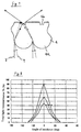
- Figures 1 and 2 show optical paths of the so-called ghost light (stray light, unnecessary reflected light) generated from a Fresnel lens or the like which causes the deterioration of contrast of a screen in a dark room.
- the condition of generating ghost light will be described by Figure 3.
- the axis of abscissas indicates the distance (mm) from the mechanical center of a screen, and the axis of ordinates indicates the outgoing angle (deg) of ghost light to the perpendicular line of the screen.
- ghost light transmitted from the Fresnel lens sheet is, as seen from Figure 3, generated only in the outer periphery of the Fresnel lens sheet, and the outgoing angle is directed toward the center of the Fresnel lens sheet.
- a curve (a) shows ghost light (2e) tracing a light ray as shown in Figure 1
- a curve (b) shows ghost light (3g) tracing a light ray as shown in Figure 2.
- the ghost light to be observed only at a specified position in the outer periphery of a screen is actually observed in a wider range than this.
- This circumstance is significantly influenced by the characteristic of a lenticular lens sheet used jointly with the Fresnel lens sheet.
- the outgoing light from the Fresnel lens sheet is diffused largely in the horizontal direction, even the light transmitted from the Fresnel lens sheet only to a specified angle is diffused in the horizontal direction after passed through the lenticular lens sheet, so that ghost light is observed in a wider angle than that shown in Figure 3.
- the calculation results of light transmittance to the angle of incidence of the conventional lenticular lens are shown in a graph (a) of Figure 4.
- the axis of ordinates indicates the total light transmittance Tt(%) of the lenticular lens sheet
- the axis of abscissas indicates the angle ⁇ (deg) of incidence of a light ray on the lenticular lens .
- the total light transmittance Tt is about 90%, so that the ghost light shown in Figure 3 is easily transmitted.
- a light ray 5 (a solid line) indicates an incident light ray with an incidence angle of 20°
- a light ray 6 (a broken line) indicates an incident light ray with an incidence angle of 30°
- the light entered the incidence side lens 4a of the lenticular lens sheet 4 at an angle above a certain angle (above 30° ) strikes black stripes 7 formed on the outgoing side of the lenticular lens sheet 3 not to come out on the observation side.
- the ghost light (stray light, unnecessary reflected light) generated by reflection in the interior of the Fresnel lens sheet is observed only at a certain specified position of the screen, and though the intensity varies, even if the observation position is changed, the position on the screen will not be changed.
- the generation status of ghost light in the Fresnel lens sheet is the same as that in the prior art, in the lenticular lens sheet in the present invention, the transmittance characteristic of outgoing light ray to the angle of an incident light ray is largely different from that of the prior art.
- the transmittance is about 50% or less.
- Figure 6 shows the construction of the lenticular lens sheet in the present invention.
- An incidence side lens 4a and an outgoing side lens 4b of the lenticular lens sheet 4 in the present invention are elliptical or circular sectional forms similarly to the conventional lenticular lens sheet.
- light rays incident at a large angle are as shown by a light ray 5 (a solid line) and a light ray 6 (a broken line) in Figure 5, have only some (the light ray 6) thereof cut by black stripes 7.
- Figure 7 shows the condition where a light ray is transmitted in the lenticular lens sheet in the present invention.
- a light ray 8 (a solid line) indicates a path with an incidence angle of 0°
- a light ray 9 (a broken line) indicates a path with an incidence angle of 20°
- a light ray with an incidence angle 20° is also cut by the black stripes 7 in the lenticular lens sheet to remarkably reduce unnecessary incident light ray which causes ghost.
- Figure 4 shows the results of calculating the total light ray transmittance of an example of a lenticular lens sheet in the present invention.
- graphs (b) and (c) are results of calculating the total light ray transmittance of an example of the lenticular lens sheet in the present invention. As shown in the graphs (b) and (c) of Figure 4, it is known that stray light with an angle of 20° or more transmitted from the Fresnel lens sheet is hardly transmitted.
- the light transmittance of an unnecessary reflected light ray from the Fresnel lens sheet is significantly influence by the position of the outgoing side lens to the main focus position of the incidence side lens. This circumstance will be described with reference to Figure 8.
- the axis of ordinates indicates the total light transmittance Tt (%) of the lenticular lens sheet, and the axis of abscissas indicates the angle ⁇ (deg) of incidence of a light ray on the lenticular lens sheet.
- Figure 8 shows the calculation results if t/f is 1.6 when the main focal distance (mm) of the incidence side lens in the lenticular lens sheet is indicated by (f) and the distance between the incidence side lens surface and a light shielding member is indicated by (t), and in the graphs (a), (b) and (c) of Figure 8, the respective ratios (hereinafter referred to as BS ratio) of the width of the light shielding member to the pitch of the incidence side lens are 45%, 60% and 70% (provided that calculation was done , taking the light transmission loss caused by a light absorbent contained in the lenticular lens sheet as 0%.).
- BS ratio the respective ratios
- the position of the outgoing side lens is remote from the main focus position of the incidence side lens designed to keep the practical horizontal angle of visibility, it is possible to remarkably lower the light transmittance to a light ray with a large incidence angle on the lenticular lens sheet.
- the light transmittance of a light ray which has an incidence angle of about 0 ° and is needed for displaying an image is also lowered, so that a desirable characteristic as a lenticular lens sheet can not be obtained.
- the position of the outgoing side lens to the main focus position of the incidence side lens is remote, the horizontal diffusion characteristic which is important as a characteristic of a lenticular lens is lowered, so it is not preferable in this respect.
- the total light transmittance to a light ray with an incidence angle of 20° on the lenticular lens sheet is low, and if the transmittance is 50 x (1 - ⁇ ) (%) or less, the ghost light can be remarkably reduced. It is more desirable that the transmittance is 30 x (1 - ⁇ ) (%) or less.
- the total light transmittance to a light ray with an incidence angle of 5° on the lenticular lens sheet is 70 % or more. It is desirable that the total light transmittance to a light ray with an incidence angle of 5 ° is 80 % or more.
- the ratio of black stripes can be heightened to reduce outside daylight reflection in a well-lighted room and improve the contrast of a screen.
- the 3-CRTs image display device light rays from three tubes, respectively are different in an angle of incidence on a lenticular lens sheet, so it is necessary to correct color shift caused by converging of light rays from three tubes, respectively on different positions of the outgoing side lens of the lenticular lens sheet.
- an image display device using one or more LCDs which is provided with a single projection lens, it is possible to converge light on a substantially feed position of an outgoing side lens of the lenticular lens sheet and correction for color shift is not needed, so that the ratio of black stripes can be heightened.
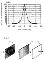
- a sheet having diffusing power is used as a Fresnel lens sheet, and an example of light ray diffusing characteristics of such a sheet is shown in Figure 9.
- most of light rays transmitted from the Fresnel lens sheet have an outgoing angle of ⁇ 10° .
- the total light transmittance is 50 % or more, so even if it is used in combination with the Fresnel lens sheet having diffusing power, there is no problem.
- the total light transmittance is measured by use of GP-1R goniometer manufactured by Murakami Color Laboratory, the contrast is evaluated by use of KL-37HW1 LCD type rear projection type projection television set manufactured by Sony Corporation, and the luminance is measure by a color color-difference meter CS-100 manufactured by Minolta Camera Co. , Ltd.
- a lenticular lens sheet so constructed that the lens pitch of a lenticular lens is 0.53mm, the thickness of a sheet is 0.62 mm, and the ratio of black stripes is 67 % is manufactured by a roll molding method using an extrusion molding machine manufactured by Toshiba Machine Co., Ltd. Black stripes are formed with black ink on the surface of this lepticular lens sheet by a screen printing method.
- the form of the above lenticular lens is expressed by the following expression.
- t/f is 0.9. (CR 2 / [1 + ⁇ 1 - (K + 1) C 2 R 2 ⁇ 1/2 ] + DR 4 + ER 6 + FR 8 + GR 10
- a Fresnel lens sheet which is combined with the above lenticular lens sheet to construct a rear projection type image display device is formed by a resin plate where a fine-particles diffuser agent is mixed, and the diffusing characteristic of the Fresnel lens sheet is shown in Figure 9.
- the results of measuring the total light transmittance Tt ( ⁇ ) (%) of the lenticular lens sheet of the present embodiment are shown in Table 3.
- the total light transmittance is the ratio of the total amount of light rays transmitted from the outgoing surface to the amount of light rays entering from the incident surface of the lenticular lens sheet (In Table 3, the measurement result on the embodiment 2 mentioned later is shown at the same time.).
- the lenticular lens sheet of the present embodiment and the described Fresnel lens sheet are installed in the described projection television set, and the results of measuring the luminance of a projection image and outside daylight reflection which becomes an index of outside daylight contrast are shown in Table 4.
- horizontal angles of visibility ⁇ H, ⁇ H, ⁇ H show the horizontal angles of visibility which are 1/2, 1/3 and 1/10, respectively to the peak luminance.
- Both the lenticular lens sheet of the embodiment 1 and that of the embodiment 2 mentioned later have a horizontal angle of visibility which causes no problem practically.
- the luminance of a projection image was measured by inputting a reference signal of a black-and-white pattern to a projection television set and measuring the white area by use of the above measuring device at a distance of 1 m away from the projection television set.
- the outside daylight reflection luminance was measured by applying modulated light of a halogen lamp to a screen at an angle of about 45° from above and measuring the luminance of the black area of the black-and-white pattern.
- the outside daylight contrast is indicated by a value obtained by dividing the white luminance of a projection image by black luminance.
- the outside daylight contrast is shows the influence of outside daylight upon the projection image light, and it means that the larger the value is, the less the contrast is deteriorated.
- a black-and-white reference signal is input to the projection television set to measure the white area luminance and the black area luminance, respectively.
- the value obtained by dividing the white luminance by the black luminance is taken as stray light contrast. It means that the larger the value is, the less the deterioration of contrast due to stray light is.
- the results of measuring the total light transmittance and contrast similarly to the embodiment 1 using the thus constructed lenticular lens sheet are shown at the same time in Table 3 and Table 4.
- the lenticular lens sheet of the comparative example has a high transmittance to an incidence angle of 20° .
- the contrast is inferior to that of the embodiments.
- ghost light such as stray light, unnecessary reflected light or the like in a projection optical system, which is generated even if outside daylight does not exist, can be reduced, and also outside daylight reflection in a well-lighted room can be reduced so as to provide a rear projection type image device excellent in contrast.
Landscapes
- Physics & Mathematics (AREA)
- General Physics & Mathematics (AREA)
- Optics & Photonics (AREA)
- Engineering & Computer Science (AREA)
- Multimedia (AREA)
- Signal Processing (AREA)
- Overhead Projectors And Projection Screens (AREA)
Applications Claiming Priority (3)
| Application Number | Priority Date | Filing Date | Title |
|---|---|---|---|
| JP214913/97 | 1997-08-08 | ||
| JP21491397 | 1997-08-08 | ||
| JP21491397 | 1997-08-08 |
Publications (2)
| Publication Number | Publication Date |
|---|---|
| EP0896244A1 true EP0896244A1 (fr) | 1999-02-10 |
| EP0896244B1 EP0896244B1 (fr) | 2004-04-14 |
Family
ID=16663660
Family Applications (1)
| Application Number | Title | Priority Date | Filing Date |
|---|---|---|---|
| EP98114898A Expired - Lifetime EP0896244B1 (fr) | 1997-08-08 | 1998-08-07 | Dispositif d'affichage d'image à projection par transparence |
Country Status (3)
| Country | Link |
|---|---|
| US (1) | US6124969A (fr) |
| EP (1) | EP0896244B1 (fr) |
| DE (1) | DE69823109T2 (fr) |
Cited By (1)
| Publication number | Priority date | Publication date | Assignee | Title |
|---|---|---|---|---|
| WO2009156027A1 (fr) * | 2008-06-25 | 2009-12-30 | Khs Ag | Procédé et dispositif pour détecter le profil de bord de bouteilles ou de récipients similaires |
Families Citing this family (4)
| Publication number | Priority date | Publication date | Assignee | Title |
|---|---|---|---|---|
| JPH10239777A (ja) * | 1997-02-28 | 1998-09-11 | Kuraray Co Ltd | 背面投写型映像表示装置 |
| KR100538220B1 (ko) * | 2003-02-06 | 2005-12-21 | 삼성전자주식회사 | 넓은 시야각을 가지는 스크린 및 이를 구비하는 프로젝션텔레비전 |
| JP2005099479A (ja) * | 2003-09-25 | 2005-04-14 | Dainippon Printing Co Ltd | 光透過性シートおよびスクリーン |
| KR100743283B1 (ko) * | 2004-03-11 | 2007-07-26 | 엘지전자 주식회사 | 프로젝션 티브이의 외광 차단장치 |
Citations (5)
| Publication number | Priority date | Publication date | Assignee | Title |
|---|---|---|---|---|
| EP0077117A1 (fr) * | 1981-10-05 | 1983-04-20 | Hitachi, Ltd. | Appareil de projection par transparence |
| EP0671653A1 (fr) * | 1994-03-11 | 1995-09-13 | Matsushita Electric Industrial Co., Ltd. | Ecran de projection par transparence et son procédé de fabrication |
| EP0706077A1 (fr) * | 1994-10-05 | 1996-04-10 | Hitachi, Ltd. | Système d'affichage d'images à projection par transparence |
| EP0736796A1 (fr) * | 1995-04-06 | 1996-10-09 | Kuraray Co., Ltd. | Ecran de projection par transparence |
| EP0772077A2 (fr) * | 1995-10-30 | 1997-05-07 | Sony Corporation | Dispositif d'affichage du type à projection |
Family Cites Families (5)
| Publication number | Priority date | Publication date | Assignee | Title |
|---|---|---|---|---|
| US5400114A (en) * | 1991-09-05 | 1995-03-21 | Hitachi, Ltd. | Rear-projection screen and a rear projection image display employing the rear-projection screen |
| DE69232810T2 (de) * | 1991-11-15 | 2003-09-11 | Kuraray Co., Ltd | Transparenter Projektionsschirm und Verfahren zu seiner Herstellung |
| KR0168879B1 (ko) * | 1992-12-25 | 1999-04-15 | 기따지마 요시또시 | 렌티큘러 렌즈, 면광원 및 액정 표시 장치 |
| US5611611A (en) * | 1994-10-05 | 1997-03-18 | Hitachi, Ltd. | Rear projection type display system |
| US5880887A (en) * | 1996-08-16 | 1999-03-09 | Dai Nippon Printing Co., Ltd. | Lenticular lens sheet, display front plate and transmission type projection screen |
-
1998
- 1998-08-06 US US09/130,107 patent/US6124969A/en not_active Expired - Fee Related
- 1998-08-07 DE DE69823109T patent/DE69823109T2/de not_active Expired - Fee Related
- 1998-08-07 EP EP98114898A patent/EP0896244B1/fr not_active Expired - Lifetime
Patent Citations (5)
| Publication number | Priority date | Publication date | Assignee | Title |
|---|---|---|---|---|
| EP0077117A1 (fr) * | 1981-10-05 | 1983-04-20 | Hitachi, Ltd. | Appareil de projection par transparence |
| EP0671653A1 (fr) * | 1994-03-11 | 1995-09-13 | Matsushita Electric Industrial Co., Ltd. | Ecran de projection par transparence et son procédé de fabrication |
| EP0706077A1 (fr) * | 1994-10-05 | 1996-04-10 | Hitachi, Ltd. | Système d'affichage d'images à projection par transparence |
| EP0736796A1 (fr) * | 1995-04-06 | 1996-10-09 | Kuraray Co., Ltd. | Ecran de projection par transparence |
| EP0772077A2 (fr) * | 1995-10-30 | 1997-05-07 | Sony Corporation | Dispositif d'affichage du type à projection |
Cited By (2)
| Publication number | Priority date | Publication date | Assignee | Title |
|---|---|---|---|---|
| WO2009156027A1 (fr) * | 2008-06-25 | 2009-12-30 | Khs Ag | Procédé et dispositif pour détecter le profil de bord de bouteilles ou de récipients similaires |
| US9909861B2 (en) | 2008-06-25 | 2018-03-06 | Khs Gmbh | Method and device for detecting the edge profile of bottles or similar containers |
Also Published As
| Publication number | Publication date |
|---|---|
| DE69823109T2 (de) | 2004-08-26 |
| DE69823109D1 (de) | 2004-05-19 |
| US6124969A (en) | 2000-09-26 |
| EP0896244B1 (fr) | 2004-04-14 |
Similar Documents
| Publication | Publication Date | Title |
|---|---|---|
| US5422691A (en) | Projection type displaying apparatus and illumination system | |
| US4941732A (en) | Transmission type projection screen | |
| US5302983A (en) | Projector | |
| US5400114A (en) | Rear-projection screen and a rear projection image display employing the rear-projection screen | |
| US5590943A (en) | Rear projection type image display apparatus and transmission type screen used therein | |
| US6502942B2 (en) | Rear projection display apparatus and translucent screen for use therein | |
| US5100222A (en) | Screen and image display apparatus | |
| US20050018148A1 (en) | Projection-type display apparatus | |
| JPH01140187A (ja) | 背面投影型ディスプレイ | |
| US5220363A (en) | Projector | |
| JP3697832B2 (ja) | 背面投射型ディスプレー装置及びスクリーンユニット | |
| JP3371654B2 (ja) | 投射型ディスプレイ装置 | |
| JP5055765B2 (ja) | 画像表示装置、及び、それに用いるフレネルレンズシート並びにスクリーン | |
| JPH11338056A (ja) | 映像表示装置 | |
| EP0896244B1 (fr) | Dispositif d'affichage d'image à projection par transparence | |
| JP2007193290A (ja) | 画像表示装置、及びそれに用いるフレネルレンズシート | |
| US6310722B1 (en) | Lenticular lens sheet and projection screen using the same | |
| EP1039337A1 (fr) | Ecran de rétroprojection | |
| JP3905648B2 (ja) | 背面投写型映像表示装置 | |
| JPH06308614A (ja) | 投写型表示装置 | |
| KR100217489B1 (ko) | 프레넬 렌즈 및 액정 표시장치 | |
| JPH08122633A (ja) | 投写レンズ及び投写型表示装置 | |
| KR0173702B1 (ko) | 프로젝터의 후면투사스크린 | |
| JP3043485B2 (ja) | 透過型スクリーン及びそれを用いた背面投写型画像ディスプレイ装置 | |
| KR100396128B1 (ko) | 액정표시장치 |
Legal Events
| Date | Code | Title | Description |
|---|---|---|---|
| PUAI | Public reference made under article 153(3) epc to a published international application that has entered the european phase |
Free format text: ORIGINAL CODE: 0009012 |
|
| AK | Designated contracting states |
Kind code of ref document: A1 Designated state(s): DE FR GB NL |
|
| AX | Request for extension of the european patent |
Free format text: AL;LT;LV;MK;RO;SI |
|
| 17P | Request for examination filed |
Effective date: 19990304 |
|
| AKX | Designation fees paid |
Free format text: DE FR GB NL |
|
| GRAP | Despatch of communication of intention to grant a patent |
Free format text: ORIGINAL CODE: EPIDOSNIGR1 |
|
| GRAS | Grant fee paid |
Free format text: ORIGINAL CODE: EPIDOSNIGR3 |
|
| GRAA | (expected) grant |
Free format text: ORIGINAL CODE: 0009210 |
|
| STAA | Information on the status of an ep patent application or granted ep patent |
Free format text: STATUS: THE PATENT HAS BEEN GRANTED |
|
| AK | Designated contracting states |
Kind code of ref document: B1 Designated state(s): DE FR GB NL |
|
| REG | Reference to a national code |
Ref country code: GB Ref legal event code: FG4D |
|
| REF | Corresponds to: |
Ref document number: 69823109 Country of ref document: DE Date of ref document: 20040519 Kind code of ref document: P |
|
| ET | Fr: translation filed | ||
| PLBE | No opposition filed within time limit |
Free format text: ORIGINAL CODE: 0009261 |
|
| 26N | No opposition filed |
Effective date: 20050117 |
|
| PGFP | Annual fee paid to national office [announced via postgrant information from national office to epo] |
Ref country code: NL Payment date: 20080803 Year of fee payment: 11 Ref country code: DE Payment date: 20080821 Year of fee payment: 11 |
|
| PGFP | Annual fee paid to national office [announced via postgrant information from national office to epo] |
Ref country code: FR Payment date: 20080818 Year of fee payment: 11 |
|
| PGFP | Annual fee paid to national office [announced via postgrant information from national office to epo] |
Ref country code: GB Payment date: 20080820 Year of fee payment: 11 |
|
| REG | Reference to a national code |
Ref country code: NL Ref legal event code: V1 Effective date: 20100301 |
|
| GBPC | Gb: european patent ceased through non-payment of renewal fee |
Effective date: 20090807 |
|
| REG | Reference to a national code |
Ref country code: FR Ref legal event code: ST Effective date: 20100430 |
|
| PG25 | Lapsed in a contracting state [announced via postgrant information from national office to epo] |
Ref country code: NL Free format text: LAPSE BECAUSE OF NON-PAYMENT OF DUE FEES Effective date: 20100301 Ref country code: FR Free format text: LAPSE BECAUSE OF NON-PAYMENT OF DUE FEES Effective date: 20090831 Ref country code: DE Free format text: LAPSE BECAUSE OF NON-PAYMENT OF DUE FEES Effective date: 20100302 |
|
| PG25 | Lapsed in a contracting state [announced via postgrant information from national office to epo] |
Ref country code: GB Free format text: LAPSE BECAUSE OF NON-PAYMENT OF DUE FEES Effective date: 20090807 |