EP0896206B1 - Abtasteinheit für eine optische Positionsmesseinrichtung - Google Patents
Abtasteinheit für eine optische Positionsmesseinrichtung Download PDFInfo
- Publication number
- EP0896206B1 EP0896206B1 EP98112848A EP98112848A EP0896206B1 EP 0896206 B1 EP0896206 B1 EP 0896206B1 EP 98112848 A EP98112848 A EP 98112848A EP 98112848 A EP98112848 A EP 98112848A EP 0896206 B1 EP0896206 B1 EP 0896206B1
- Authority
- EP
- European Patent Office
- Prior art keywords
- regions
- incremental
- division
- scanning
- read
- Prior art date
- Legal status (The legal status is an assumption and is not a legal conclusion. Google has not performed a legal analysis and makes no representation as to the accuracy of the status listed.)
- Expired - Lifetime
Links
- 230000003287 optical effect Effects 0.000 title claims description 51
- 230000000694 effects Effects 0.000 claims abstract description 34
- 230000000737 periodic effect Effects 0.000 claims abstract description 18
- 238000001914 filtration Methods 0.000 description 19
- 238000001514 detection method Methods 0.000 description 11
- 238000013461 design Methods 0.000 description 9
- 238000013459 approach Methods 0.000 description 3
- 230000005693 optoelectronics Effects 0.000 description 3
- 238000011156 evaluation Methods 0.000 description 2
- 230000005484 gravity Effects 0.000 description 2
- 230000035945 sensitivity Effects 0.000 description 2
- 229910000831 Steel Inorganic materials 0.000 description 1
- 230000015572 biosynthetic process Effects 0.000 description 1
- 230000001419 dependent effect Effects 0.000 description 1
- 239000011521 glass Substances 0.000 description 1
- 238000003384 imaging method Methods 0.000 description 1
- 230000010354 integration Effects 0.000 description 1
- 238000005259 measurement Methods 0.000 description 1
- 230000007935 neutral effect Effects 0.000 description 1
- 239000010959 steel Substances 0.000 description 1
- 238000012546 transfer Methods 0.000 description 1
Images


Classifications
-
- G—PHYSICS
- G01—MEASURING; TESTING
- G01D—MEASURING NOT SPECIALLY ADAPTED FOR A SPECIFIC VARIABLE; ARRANGEMENTS FOR MEASURING TWO OR MORE VARIABLES NOT COVERED IN A SINGLE OTHER SUBCLASS; TARIFF METERING APPARATUS; MEASURING OR TESTING NOT OTHERWISE PROVIDED FOR
- G01D5/00—Mechanical means for transferring the output of a sensing member; Means for converting the output of a sensing member to another variable where the form or nature of the sensing member does not constrain the means for converting; Transducers not specially adapted for a specific variable
- G01D5/26—Mechanical means for transferring the output of a sensing member; Means for converting the output of a sensing member to another variable where the form or nature of the sensing member does not constrain the means for converting; Transducers not specially adapted for a specific variable characterised by optical transfer means, i.e. using infrared, visible, or ultraviolet light
- G01D5/32—Mechanical means for transferring the output of a sensing member; Means for converting the output of a sensing member to another variable where the form or nature of the sensing member does not constrain the means for converting; Transducers not specially adapted for a specific variable characterised by optical transfer means, i.e. using infrared, visible, or ultraviolet light with attenuation or whole or partial obturation of beams of light
- G01D5/34—Mechanical means for transferring the output of a sensing member; Means for converting the output of a sensing member to another variable where the form or nature of the sensing member does not constrain the means for converting; Transducers not specially adapted for a specific variable characterised by optical transfer means, i.e. using infrared, visible, or ultraviolet light with attenuation or whole or partial obturation of beams of light the beams of light being detected by photocells
- G01D5/36—Forming the light into pulses
- G01D5/366—Particular pulse shapes
-
- G—PHYSICS
- G01—MEASURING; TESTING
- G01D—MEASURING NOT SPECIALLY ADAPTED FOR A SPECIFIC VARIABLE; ARRANGEMENTS FOR MEASURING TWO OR MORE VARIABLES NOT COVERED IN A SINGLE OTHER SUBCLASS; TARIFF METERING APPARATUS; MEASURING OR TESTING NOT OTHERWISE PROVIDED FOR
- G01D5/00—Mechanical means for transferring the output of a sensing member; Means for converting the output of a sensing member to another variable where the form or nature of the sensing member does not constrain the means for converting; Transducers not specially adapted for a specific variable
- G01D5/12—Mechanical means for transferring the output of a sensing member; Means for converting the output of a sensing member to another variable where the form or nature of the sensing member does not constrain the means for converting; Transducers not specially adapted for a specific variable using electric or magnetic means
- G01D5/244—Mechanical means for transferring the output of a sensing member; Means for converting the output of a sensing member to another variable where the form or nature of the sensing member does not constrain the means for converting; Transducers not specially adapted for a specific variable using electric or magnetic means influencing characteristics of pulses or pulse trains; generating pulses or pulse trains
- G01D5/245—Mechanical means for transferring the output of a sensing member; Means for converting the output of a sensing member to another variable where the form or nature of the sensing member does not constrain the means for converting; Transducers not specially adapted for a specific variable using electric or magnetic means influencing characteristics of pulses or pulse trains; generating pulses or pulse trains using a variable number of pulses in a train
- G01D5/2454—Encoders incorporating incremental and absolute signals
- G01D5/2455—Encoders incorporating incremental and absolute signals with incremental and absolute tracks on the same encoder
- G01D5/2457—Incremental encoders having reference marks
Definitions
- the present invention relates to a scanning unit for an optical position measuring device according to the preamble of claim 1.
- Known optical position measuring devices deliver incremental signals with respect to the relative offset of two parts that are movable relative to one another usually so-called reference pulse signals. About these signals can at a defined relative position of the moving parts an exact absolute reference of the position measurement can be established. For generation of the reference pulse signals are on the scale of the position measuring device fields with reference markings in one or more places arranged.
- the scanning unit of the optical position measuring device includes at least one reference mark scanning field, via that with the relative position of scale and scanning unit to be detected a corresponding reference pulse signal can be generated.
- the reference markings are known from US Pat. No. 4,263,506 on the scale next to the graduation track with the incremental graduation to arrange.
- the problem here is that in the case a possible rotation of the scale and scanning unit around an axis the exact assignment of the reference pulse signal perpendicular to the scale or scanning plane at a certain period of the incremental signals is no longer guaranteed.
- the object of the present invention is therefore, in particular, a scanning unit to create for an optical position measuring device in which the Problems mentioned above in connection with the detection of a reference pulse signal be minimized.
- An optical position measuring device with one designed according to the invention Scanning unit is the subject of claim 11.
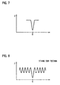
- the optical filter effect provided according to the invention now ensures that the reference pulse signal at the respective Reference position is reliably detectable. Adjacent to the reference position the periodically modulated incremental signal component is no longer on Reference pulse signal before, but a signal component with a largely constant or constant amplitude. At least the fundamental wave of the incremental signal component the reference pulse signal is filtered. A safer one or easier detection of the reference pulse signal at the reference position is possible.
- phase structures mentioned are used for filtering in the context of an advantageous embodiment of the scanning unit according to the invention and these areas also have a focusing optical effect, further advantages of the scanning unit according to the invention result. In particular, this results in a lower sensitivity when the scanning unit is tilted about the line direction of the scanned division structures.
- the scale is slightly tilted about the line or web direction, a much smaller proportion of the light bundles passing through the scanning plate during the second pass is cut off due to the selected configuration than in a conventional configuration of the scanning unit.
- the assignment of the reference pulse signal to the corresponding incremental signal period period remains guaranteed due to the proximity of the neutral fulcrum to the scale even with larger tilting than is the case with a conventional scanning arrangement.
- a higher signal intensity can be achieved on the detector side if focusing optical elements are used.
- the filtering according to the invention also by the appropriate Formation or structuring of one or more detector elements take place.
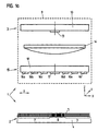
- Figure 1a is a schematic side view of an optical position measuring device in connection with a first variant of an invention trained scanning unit shown.
- the illustrated optical Position measuring device 1 is a reflected light measuring system for detecting the Relative position of two mutually displaceable objects, which are not shown in Figure 1 for reasons of clarity.
- One of the two objects is with the scale 2 of the position measuring device 1 connected, the other object to the scanning unit 3.
- each other Objects displaceable in the measuring direction x can be, for example around the workpiece as well as the tool of a numerically controlled Act machine tool.
- the scanning unit according to the invention can alternatively to shown use in a reflected light measuring system also in connection with an optical position measuring device working in transmitted light become. It is of course also possible to use an optical position measuring device to be provided with a scanning unit designed according to the invention, which determines the detection of rotational relative movements of two objects is.
- the illustrated embodiment of an optical position measuring device is therefore in no way restrictive in connection with of the present invention, i.e. the measures according to the invention in connection with the generation or acquisition of reference pulse signals can of course in connection with various optical position measuring devices are used.
- the variant of an optical position measuring device 1 shown in FIG. 1a comprises, on the one hand, the preferably stationary linear scale 2, consisting of a graduation carrier 4 on which at least one graduation track 5 is arranged in the measuring direction x.
- the division track 5 is optically scanned by the scanning unit 3, which is movable to this end, in order to determine the relative position of the two objects to one another.
- the graduation track 5 arranged on the graduation carrier 4 consists of a sequence of reflecting and non-reflecting regions 6a, 6b which extend perpendicular to the measuring direction x in the y direction.
- the graduation track 5 comprises an incremental graduation 7, which supplies periodically modulated incremental signals in the optical scanning provided, and one or more fields with reference markings 8, which identify predetermined absolute positions along the scale 2 or the graduation track 5 with the incremental graduation 7.
- the fields with the reference markings 8 are consequently integrated into the same graduation track 5 as the incremental graduation 7.
- a different number of such reference markings 8 can of course be along the required Measuring length are provided; this also includes, for example, the known distance-coded arrangement of several reference markings. The advantages of such an arrangement of the reference markings 8 have already been discussed above.
- the illustrated optical position measuring device 1 further includes the relative to the scale 2 in the measuring direction x movable scanning unit 3, consisting from several components, preferably in one - schematic indicated - housing 9 are arranged.
- the various components the scanning unit 3 in the exemplary embodiment shown counts, inter alia, a carrier board 10 with a light source and several optoelectronic Detector elements 13, an optics 14 and a scanning plate 15 with a plurality of scan fields 16a-16f and 17.
- the scan fields 16a-16f are open a translucent support member 18 is arranged.
- the incremental signals are so-called (quasi) single-field scanning, the particularly with regard to insensitivity to pollution Offers advantages.
- a known four-field scanning can also be used to generate the incremental signals in connection with the invention Measures are used etc.
- the optics 14 provided in the example, i.e. in principle, the following considerations according to the invention can be also on an optical position measuring device without collimation optics transfer etc.
- the scanning unit 3 is for generation of the incremental signals on the scanning plate 15 a plurality of incremental division scanning fields 16a-16f provided on a carrier element 18, the for example, according to FIG. 8 of EP 0 735 346 A2 mentioned are.
- the optical scanning of the incremental graduation 7 results thus four incremental signals, each phase-shifted by 90 °.
- Reference mark 8 is another scanning field 17 on the Scanning plate 15 arranged, which in the manner described below and is designed according to the invention.
- the reference mark scan field 17 is at least one reference pulse detector element on the carrier board 10 side 13 assigned via which the detection of the reference pulse signal at at least one predetermined relative position of Scale 2 and scanning unit 3 takes place.
- FIG. 1b A top view of part of the scale 2 with the scanned incremental division 7 and with a reference marking integrated in the incremental graduation 7 8 is shown in Figure 1b.
- the light parts represent the reflective areas 6a of the graduation track 5, which lie in between dark areas 6b are non-reflective.
- With the non-reflective trained areas 6b may e.g. around etched areas on the fundamentally reflective graduation carrier 4 made of steel act.
- the measures according to the invention can of course also in Connection with a transmitted light measuring system can be used. On the The scale side would then be transmitting instead of the reflecting areas Provide areas as well as instead of the non-reflective areas corresponding opaque areas.
- FIG. 1c A top view of a scanning plate 15 of the invention Scanning unit 3 is shown in Figure 1c.
- a transparent support element 18 for example made of glass, are different scanning fields 16a-16f, 17 arranged in the measuring direction x adjacent to each other, which for Scanning the incremental graduation 7 and for scanning the reference mark 8 serve on the scale 2.
- the scanning plate 15 is an embodiment of the total of six Incremental division scanning fields 16a-16f according to the already mentioned FIG. 8 from EP 0 735 346 A2, which is a (quasi) single-field scanning and the generation of four incremental signals that are 90 ° out of phase enable.
- the selected division period in the incremental division sample fields 16a-16d is 40 ⁇ m in the example shown.
- a further scanning field 17 which for scanning the reference mark 8 is provided on the scale 2.
- a reference mark scanning field 17 is shown.
- the arrangement or Sequence of the permeable and impermeable areas 17a, 17b within the reference mark scanning field 17 has been adapted to scan the Reference mark 8 selected.
- the through the reference mark scan field 17 resulting optical filter effect is selected by the Width of the permeable areas 17a of this scanning field 17 in the measuring direction x causes.
- the width in the x direction becomes identical to the division period TP of the scanned incremental division 7 or an integer Multiples of them chosen.
- the periodic incremental signal component consequently significantly reduce the reference pulse signal or eliminate.
- the advantageous embodiment of the reference mark scanning field 17 and alternative approaches for filtering this signal component are explained in detail using the following exemplary embodiments.
- FIG. 1d shows a top view of the carrier board 10 of the scanning unit 3, which u.a. in addition to the light source 11, the various optoelectronic detector elements 12a-12d, 13, preferably photo elements, contains for detection of the different scanning signals.
- the four detector elements 12a-12d for detecting the incremental signals from the incremental division scanning fields 16a-16f is a further reference pulse detector element 13 to detect the reference pulse signals the reference mark scanning field 17 is provided.
- FIGS. 1a-1d show the various detector elements 12a-12d, 13 arranged on the carrier board 10 in the y direction, i.e. perpendicular to the measuring direction x.
- the beams are reflected transversely to Measuring direction x, i.e. in the y direction.
- the deflection of the rays, which are used to generate the incremental signals as the phase-determining effect on the rays also results from the additionally provided transverse structure in the incremental division scanning fields 16a-16f.
- a suitable optical deflection element in the form of a wedge prism on the side of the scanning plate 15 in the region of the reference marking scanning field 17.
- the optics 14 could also have a partial area with a correspondingly deflecting optical effect.
- a different scanning arrangement can accordingly also be provided, for example a conventional four-field scanning with detector elements etc. arranged parallel to the measuring direction x.
- FIG. 2a A plan view of a second exemplary embodiment of a reference marking scanning field 27 designed according to the invention is shown in FIG. 2a, which shows a section of the scanning plate of the scanning unit.
- the portion of the reference marking scanning field 27 marked in FIG. 2a is shown enlarged in FIG. 2b.
- This embodiment variant of a reference marking scanning field 27 can of course also be used in connection with a scanning geometry according to the previous example.
- a structuring in the measuring direction x which consists of a sequence of transparent and opaque regions 27a, 27b, which extend in the y direction, is again provided within the reference marking scanning field 27.
- the sequence of the transparent and opaque areas 27a, 27b or the arrangement of their centers of gravity in the measuring direction x is again selected depending on the sequence of the permeable and impervious areas of the reference marking (not shown) to be scanned on the scale.
- a periodic structuring thereof is provided perpendicularly or transversely to the measuring direction x, ie in the y direction.
- the elongated, transparent or opaque areas 27a, 27b are subdivided into partial areas 27a ', 27a ", 27b', 27b".
- the adjacent or adjacent partial areas 27a ', 27a "or 27b', 27b” are arranged offset within each transparent or opaque area 27a, 27b by half a division period TP / 2 of the scanned incremental graduation.
- this offset of the partial areas 27a ', 27a ", 27b', 27b” in the x direction reference is made in particular to the enlarged partial view in FIG. 2b.
- a total of 10 partial regions 27a ′, 27a ′′, 27b ′, 27b ′′ are provided for each transparent or opaque region 27a.
- the possible scanning of a division period TP of 40 ⁇ m is a width of the scanning field 27 provided in the y-direction of 4mm.
- Such additional structuring of the reference mark scanning field 27 now also has the consequence that an optical filter effect when scanning the reference mark on the scale results in the periodic portion of the incremental signals in the reference pulse signal adjacent to the reference position or at least the corresponding fundamental wave component of the incremental signals is filtered. So result from scanning the incremental division from the different mutually displaceable partial regions 27a ', 27a "partial signals with antiphase signal modulation. The entire periodic The percentage of incremental signals is averaged out, i.e. it just remains a signal component with constant signal amplitude, which over the detector element associated with the reference mark scanning field 27 to the reference position "0" is detected. Towards this Signal component has one for the reference pulse signal at the reference position the detection of sufficient modulation or signal intensity so that a reliable detection of this signal is guaranteed.
- FIGS. 2a and 2b by the suitable design or structuring of the reference mark scanning field one again compared to the first embodiment of Figures 1a-1d improved filter effect. So lies between the scanned scale and the scanning unit usually has an intensity distribution due to diffraction effects before that filtering based only on the appropriate widths of the permeable areas of the reference mark scanning field.
- the scale changes if the scale is tilted around the y-axis the available openings of the permeable Areas of the reference mark scanning field, so that also in this If no optimal filter effect results.
- the in Figures 2a and 2b proposed embodiment of the reference mark scanning field 27 already an improved filter effect.
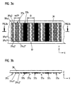
- FIG. 3a shows the top view of an exemplary embodiment of a correspondingly designed reference marking scanning field 37.
- FIG. 3b shows a cross section through the line drawn in FIG. 3a.
- the reference marking scanning field 37 has permeable regions 37a and impermeable regions 37b which are arranged adjacent in the measuring direction x.
- a certain phase structuring is provided within the permeable areas 37a in addition to filtering the periodic incremental signal component in the reference pulse signal.
- This consists of regions 37a.1, 37a.2 arranged alternately in succession in the measuring direction x, with different refractive indices for the beams passing through, which is to be indicated in FIGS. 3a and 3b by the hatched and non-hatched regions 37a.1, 37a.2.
- a further structuring in the y direction is provided such that partial areas 37a.1 ', 37a.1'',37a.2', 37a.2 "adjoining each other in the y direction half a division period TP of the scanned incremental division are arranged offset from one another.
- the transmissive areas 37a of the reference marking scanning field are consequently designed as diffractive optical elements which, on the one hand, have a focusing optical effect for the rays of light passing through.
- the associated focal lines are each offset by half a division period and thus the desired optical filter effect for the incremental signal component on
- the signal components from partial regions 37a.1 ', 37a.1'',37a.2', 37a.2 "which are adjacent in the y direction are modulated in opposite phase and cancel each other out on average.
- the respective width D of these areas 37a in Measuring direction x should preferably be chosen larger.
- the widths D of the permeable regions 37a of one so formed Reference mark scanning field 37 due to the focusing effect of diffractive optical elements on the order of two or more graduation periods of the sampled incremental graduation are formed become. In this way, a higher one can be used on the detector side Signal intensity can be achieved.
- such a Design an advantageous further effect in the detection of Reference pulse signal.
- the distance between the centers of gravity of those areas with the same refractive indices should also preferably be chosen so that n * TP where n is an integer.
- the width D is the dimension permeable areas 37a in the x-direction such that taking into account the imaging factor of the focusing optical Elements the permeable areas 37a have a width D that the Division period TP corresponds to the incremental division.
- Diffractive cylinder zone plates with a binary structure or Fresnel cylinder lenses with a blazed structure can be used as suitable diffractive elements in the permeable partial regions 37a.
- phase-matched Fresnel cylindrical lens elements are also suitable in an advantageous manner.
- optical elements in the form of refractive cylindrical lenses can of course also be used in the permeable sub-areas of the scanning field. Both the aforementioned variants of focusing optical elements and further alternatives with the specified optical properties can be integrated into the scanning unit according to the invention or into the reference marking scanning field.
- the present invention not only an exact focusing of a collimated To understand the light beam, as in the embodiment shown the case is. Rather, only one that is at least partially focused Effect of these elements can be provided depending on the scanning arrangement. For example, a partial focusing effect in the case of lighting without collimator optics or in the case of partially collimated lighting be enough.
- Filtering approaches with the aid of amplitude or phase structures in the reference mark scanning field can of course also filter variants can be used that combine these two principles.
- Filtering approaches with the aid of amplitude or phase structures in the reference mark scanning field can of course also filter variants can be used that combine these two principles.
- For example can be approximately in the embodiment of Figures 2a and 2b the permeable areas 27a of the reference mark scanning field 27 with a substructuring according to the exemplary embodiment in FIGS. 3a and 3b. This results in a combined filter effect Basis of filtering amplitude and phase structures.
- an oblique arrangement of the permeable and impermeable areas 47a, 47b within the reference marking scanning field 47 on the scanning plate 48 is therefore also possible as a filter structure.
- the various areas 47a, 47b are arranged at an angle ⁇ with respect to the scale incremental division within the reference marking scanning field 47.
- the angle ⁇ is to be chosen such that the beginning and end of the areas 47a, 47b differ over their length l y by one division period of the scanned division period TP in their x coordinate. That is, the areas 47a, 47b extend in the x direction due to their inclination with respect to the incremental division in each case over a division period of the scanned incremental division.
- FIG. 5 is a V-shaped arrangement the permeable and impermeable areas 57a, 58b within the Reference mark scanning field 57 on the scanning plate 58 as a filter structure also possible to eliminate the periodic signal component to effect on the reference pulse signal.
- the arrangement of the two V-legs takes place at the angles ⁇ relative to the scale incremental division. Regarding the appropriate choice of this angle, the two apply V-leg that this due to their inclination to the incremental division in the x direction over a division period of the scanned Extend incremental division.
- Vernier filters are the permeable areas from the example of the reference mark scanning field from Figure 1c opposite the corresponding positions of the omitted lines of the reference marking of the scale be moved.
- cosine-shaped slot openings can also be used with a width of two graduation periods on the scanning plate for filtering be used.
- the slot openings and / or the phase structures can also be used have a curved course etc.
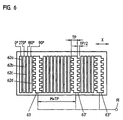
- Detector elements 62a are thus provided on a corresponding carrier board for this purpose -62d is provided for the incremental signals, which are arranged and connected in groups.
- the reference pulse detector elements 63, 63 ', 63 are in turn arranged between the groups of these detector elements.
- a first reference pulse detector element 63 is provided adjacent to a first group of four of detector elements 62a-62d; this is followed by two groups of four of detector elements for the incremental signals, to which a second reference pulse detector element 63 ', a further group of four detector elements for the incremental signals and finally a third reference pulse detector element 63 "are arranged.
- a connection of the first detector elements from the left in the groups of four results in a 0 ° scanning signal, the connection of the second detector elements in each case a 90 ° scanning signal etc.
- the reference pulse signal present at the signal tap RI in turn results from the indicated parallel connection of the three reference pulse detector elements 63, 63'63 ''.
- the arrangement variant shown for the various detector elements is a function of the structure of the reference marking to be detected and is matched to the same accordingly. In connection with the spacing between adjacent reference pulse detector elements 63, 63 ', 63 ", it should be noted in the connection variant of the detector elements described that this is an integer multiple M of the division period TP of the scanned incremental division.
- each reference pulse detector element 63, 63'"63" corresponds to a division period TP in the exemplary embodiment shown.
- the reference pulse detector elements 63, 63 ', 63''each have a certain filtering structure perpendicular to the measuring direction x.
- individual partial areas of an individual reference pulse detector element 63, 63 ', 63 "are offset from one another by half a division period in the measuring direction x different areas.
- the undesired periodic portion of the incremental signals adjacent to the reference position can thus also be eliminated according to the invention by such a filtering on the detector side.
Landscapes
- Physics & Mathematics (AREA)
- General Physics & Mathematics (AREA)
- Optical Transform (AREA)
- Length Measuring Devices By Optical Means (AREA)
- Transmission And Conversion Of Sensor Element Output (AREA)
- Body Structure For Vehicles (AREA)
- Vehicle Body Suspensions (AREA)
- Eye Examination Apparatus (AREA)
Applications Claiming Priority (2)
| Application Number | Priority Date | Filing Date | Title |
|---|---|---|---|
| DE19734136 | 1997-08-07 | ||
| DE19734136 | 1997-08-07 |
Publications (3)
| Publication Number | Publication Date |
|---|---|
| EP0896206A2 EP0896206A2 (de) | 1999-02-10 |
| EP0896206A3 EP0896206A3 (de) | 1999-03-10 |
| EP0896206B1 true EP0896206B1 (de) | 2002-12-11 |
Family
ID=7838220
Family Applications (2)
| Application Number | Title | Priority Date | Filing Date |
|---|---|---|---|
| EP98112848A Expired - Lifetime EP0896206B1 (de) | 1997-08-07 | 1998-07-10 | Abtasteinheit für eine optische Positionsmesseinrichtung |
| EP98945093A Expired - Lifetime EP1002219B1 (de) | 1997-08-07 | 1998-07-24 | Optische positionsmesseinrichtung |
Family Applications After (1)
| Application Number | Title | Priority Date | Filing Date |
|---|---|---|---|
| EP98945093A Expired - Lifetime EP1002219B1 (de) | 1997-08-07 | 1998-07-24 | Optische positionsmesseinrichtung |
Country Status (6)
| Country | Link |
|---|---|
| US (2) | US6392224B1 (enExample) |
| EP (2) | EP0896206B1 (enExample) |
| JP (2) | JP2001512818A (enExample) |
| AT (2) | ATE229642T1 (enExample) |
| DE (4) | DE19830925A1 (enExample) |
| WO (1) | WO1999008074A1 (enExample) |
Families Citing this family (60)
| Publication number | Priority date | Publication date | Assignee | Title |
|---|---|---|---|---|
| DE19830925A1 (de) | 1997-08-07 | 1999-02-11 | Heidenhain Gmbh Dr Johannes | Abtasteinheit für eine optische Positionsmeßeinrichtung |
| DE19859670A1 (de) | 1998-12-23 | 2000-06-29 | Heidenhain Gmbh Dr Johannes | Abtastkopf und Verfahren zu dessen Herstellung |
| EP1028309B1 (de) * | 1999-02-04 | 2003-04-16 | Dr. Johannes Heidenhain GmbH | Optische Positionsmesseinrichtung |
| DE60033075T3 (de) * | 1999-04-16 | 2012-08-30 | Canon K.K. | Kodierer |
| US6545262B1 (en) | 1999-06-04 | 2003-04-08 | Dr. Johannes Heidenhein Gmbh | Position measuring system |
| DE19962278A1 (de) * | 1999-12-23 | 2001-08-02 | Heidenhain Gmbh Dr Johannes | Positionsmeßeinrichtung |
| FR2808167B1 (fr) * | 2000-04-28 | 2005-03-18 | Mars Alimentaire | Procede de realisation de confiseries en vrac |
| DE10022619A1 (de) * | 2000-04-28 | 2001-12-06 | Heidenhain Gmbh Dr Johannes | Abtasteinheit für eine optische Positionsmesseinrichtung |
| DE10020575A1 (de) * | 2000-04-28 | 2001-10-31 | Heidenhain Gmbh Dr Johannes | Abtasteinheit für eine optische Positionsmesseinrichtung |
| DE10020895B4 (de) * | 2000-04-29 | 2011-07-28 | Rodi, Anton, 69181 | Positionsgebervorrichtung |
| US6713756B2 (en) * | 2000-05-09 | 2004-03-30 | Olympus Corporation | Optical encoder and optical rotary encoder |
| DE10029380A1 (de) * | 2000-06-20 | 2002-01-03 | Pwb Ruhlatec Ind Prod Gmbh | Taktlineal oder Taktscheibe |
| DE10058239B4 (de) * | 2000-11-17 | 2012-01-26 | Dr. Johannes Heidenhain Gmbh | Positionsmeßeinrichtung |
| JP4720058B2 (ja) * | 2000-11-28 | 2011-07-13 | 株式会社Sumco | シリコンウェーハの製造方法 |
| GB0109057D0 (en) * | 2001-04-11 | 2001-05-30 | Renishaw Plc | Absolute postition measurement |
| JP2005524050A (ja) * | 2001-08-30 | 2005-08-11 | マイクロイー システムズ コーポレイション | 高調波抑制光検出器アレイ |
| EP1427985B1 (de) * | 2001-09-04 | 2008-11-19 | Dr. Johannes Heidenhain GmbH | Positionsmesseinrichtung und verfahren zum betrieb einer positionsmesseinrichtung |
| DE10217726A1 (de) * | 2002-04-17 | 2003-11-27 | Heidenhain Gmbh Dr Johannes | Optische Positionsmesseinrichtung |
| DE10244234A1 (de) * | 2002-09-23 | 2004-03-25 | Dr. Johannes Heidenhain Gmbh | Positionsmesseinrichtung |
| DE10319609A1 (de) * | 2003-05-02 | 2004-11-18 | Dr. Johannes Heidenhain Gmbh | Optoelektronische Detektoranordnung |
| GB0316921D0 (en) * | 2003-07-19 | 2003-08-27 | Renishaw Plc | Reader for a scale marking |
| DE10338991A1 (de) * | 2003-08-18 | 2005-03-17 | Dr. Johannes Heidenhain Gmbh | Positionsmesseinrichtung |
| DE10346380B4 (de) * | 2003-09-26 | 2014-01-16 | Dr. Johannes Heidenhain Gmbh | Positionsmesseinrichtung |
| DE10347604A1 (de) * | 2003-10-14 | 2005-05-12 | Heidenhain Gmbh Dr Johannes | Optische Positionsmesseinrichtung |
| EP1577645B1 (en) | 2004-03-17 | 2007-09-05 | Canon Kabushiki Kaisha | Optical encoder |
| JP4498024B2 (ja) * | 2004-06-15 | 2010-07-07 | キヤノン株式会社 | 光学式エンコーダ |
| GB0413710D0 (en) * | 2004-06-21 | 2004-07-21 | Renishaw Plc | Scale reading apparatus |
| US20050285026A1 (en) * | 2004-06-25 | 2005-12-29 | Fanuc Ltd | Linear encoder |
| JP4054817B2 (ja) * | 2004-08-20 | 2008-03-05 | シャープ株式会社 | 光学式エンコーダおよびそれを用いた電子機器 |
| JP4908764B2 (ja) * | 2005-02-04 | 2012-04-04 | キヤノン株式会社 | 光学式エンコーダ |
| DE102005006247A1 (de) * | 2005-02-11 | 2006-08-17 | Dr. Johannes Heidenhain Gmbh | Positionsmesseinrichtung |
| DE102005023984A1 (de) * | 2005-05-20 | 2006-11-23 | Dr. Johannes Heidenhain Gmbh | Positionsmessgerät |
| US20070024865A1 (en) * | 2005-07-26 | 2007-02-01 | Mitchell Donald K | Optical encoder having slanted optical detector elements for harmonic suppression |
| US7552873B2 (en) * | 2005-09-14 | 2009-06-30 | Avago Technologies Ecbu Ip (Singapore) Pte. Ltd. | Transmissive optical encoder |
| DE102006024579B4 (de) * | 2006-05-18 | 2016-09-29 | Dr. Johannes Heidenhain Gmbh | Vorrichtung zur Bestimmung der Position eines entlang mindestens einer Verschieberichtung bewegbaren Objektes |
| US7400269B2 (en) * | 2006-11-09 | 2008-07-15 | Avago Technologies Ecbu Ip Pte Ltd | Coding element with integrated limit switch |
| JP5147368B2 (ja) * | 2006-11-20 | 2013-02-20 | ドクトル・ヨハネス・ハイデンハイン・ゲゼルシヤフト・ミツト・ベシユレンクテル・ハフツング | エンコーダ |
| US8011112B2 (en) * | 2006-12-07 | 2011-09-06 | Leica Geosystems Ag | Method and apparatus for determining positions |
| US7943897B2 (en) * | 2007-06-20 | 2011-05-17 | Sharp Kabushiki Kaisha | Optical encoder and electronic equipment |
| US20090027692A1 (en) * | 2007-07-24 | 2009-01-29 | Mitutoyo Corporation | Reference signal generating configuration for an interferometric miniature grating encoder readhead using fiber optic receiver channels |
| US7965393B2 (en) | 2007-07-24 | 2011-06-21 | Mitutoyo Corporation | Reference signal generating configuration for an interferometric miniature grating encoder readhead using fiber optic receiver channels |
| US7973941B2 (en) * | 2007-07-24 | 2011-07-05 | Mitutoyo Corporation | Reference signal generating configuration for an interferometric miniature grating encoder readhead using fiber optic receiver channels |
| EP2163860B2 (en) † | 2008-09-10 | 2014-03-05 | Fagor, S.Coop. | Optoelectronic measuring device |
| JP5641746B2 (ja) * | 2010-02-12 | 2014-12-17 | 株式会社ミツトヨ | 光電式エンコーダ |
| EP2579005A4 (en) | 2010-05-31 | 2013-10-23 | Yaskawa Denki Seisakusho Kk | ROTATABLE ENCODER, ROTATABLE ENGINE AND ROTATABLE MOTOR SYSTEM |
| DE102012210309A1 (de) * | 2012-06-19 | 2013-12-19 | Dr. Johannes Heidenhain Gmbh | Positionsmesseinrichtung |
| JP2014098666A (ja) * | 2012-11-15 | 2014-05-29 | Canon Inc | インクリメンタルエンコーダ |
| GB201301186D0 (en) | 2012-12-20 | 2013-03-06 | Renishaw Plc | Optical element |
| JP2016532096A (ja) * | 2013-10-01 | 2016-10-13 | レニショウ パブリック リミテッド カンパニーRenishaw Public Limited Company | 位置測定エンコーダ |
| JP6128328B2 (ja) * | 2013-11-05 | 2017-05-17 | 株式会社安川電機 | エンコーダ、エンコーダ付きモータ、サーボシステム |
| WO2015078860A1 (en) | 2013-11-26 | 2015-06-04 | Renishaw Plc | Metrological scale |
| JP6497848B2 (ja) * | 2014-04-14 | 2019-04-10 | キヤノン株式会社 | アブソリュートエンコーダ、処理方法、プログラム、駆動装置、および産業機械 |
| JP6684087B2 (ja) * | 2015-12-18 | 2020-04-22 | セイコーNpc株式会社 | 光エンコーダ |
| CN105758435B (zh) * | 2016-04-14 | 2018-02-09 | 清华大学深圳研究生院 | 一种绝对式光栅尺 |
| DE102018200449A1 (de) | 2018-01-12 | 2019-07-18 | Dr. Johannes Heidenhain Gmbh | Positionsmesseinrichtung |
| DE102018202556A1 (de) * | 2018-02-20 | 2019-08-22 | Dr. Johannes Heidenhain Gmbh | Optische Positionsmesseinrichtung |
| EP3623769A1 (en) | 2018-09-12 | 2020-03-18 | Renishaw PLC | Measurement device |
| GB201916662D0 (en) | 2019-11-15 | 2020-01-01 | Renishaw Plc | Encoder apparatus |
| GB201916641D0 (en) | 2019-11-15 | 2020-01-01 | Renishaw Plc | Position measurement device |
| DE102019219151A1 (de) * | 2019-12-09 | 2021-06-10 | Dr. Johannes Heidenhain Gesellschaft Mit Beschränkter Haftung | Optische Positionsmesseinrichtung |
Family Cites Families (20)
| Publication number | Priority date | Publication date | Assignee | Title |
|---|---|---|---|---|
| SE379241B (enExample) | 1974-01-15 | 1975-09-29 | Aga Ab | |
| US4263506A (en) | 1978-12-21 | 1981-04-21 | Hewlett-Packard Company | Pulse generating apparatus |
| DE3007311C2 (de) | 1980-02-27 | 1985-11-28 | Dr. Johannes Heidenhain Gmbh, 8225 Traunreut | Digitales lichtelektrisches Längen- oder Winkelmeßsystem |
| DE3204012C1 (de) | 1982-02-05 | 1983-02-03 | Dr. Johannes Heidenhain Gmbh, 8225 Traunreut | Inkrementale Messeinrichtung |
| DE3536466A1 (de) * | 1985-10-12 | 1987-04-16 | Bodenseewerk Geraetetech | Nullimpulserzeuger zur erzeugung eines impulses bei erreichen einer vorgegebenen lage eines traegers |
| DE3616144A1 (de) | 1986-05-14 | 1987-11-19 | Heidenhain Gmbh Dr Johannes | Fotoelektrische messeinrichtung |
| US4866268A (en) | 1988-05-20 | 1989-09-12 | General Motors Corporation | Optical fast synchronization shaft position and speed sensor |
| US5279044A (en) * | 1991-03-12 | 1994-01-18 | U.S. Philips Corporation | Measuring device for determining an absolute position of a movable element and scale graduation element suitable for use in such a measuring device |
| US5274229A (en) * | 1991-06-11 | 1993-12-28 | Hewlett-Packard Company | Absolute position encoder |
| US5241172A (en) * | 1991-11-04 | 1993-08-31 | Hewlett-Packard Company | Variable pitch position encoder |
| DE4203073C2 (de) | 1992-02-04 | 1994-12-15 | Heidenhain Gmbh Dr Johannes | Positionsmeßeinrichtung |
| DE4316221C2 (de) * | 1993-05-14 | 1995-11-23 | Heidenhain Gmbh Dr Johannes | Positionsmeßeinrichtung |
| EP0662603B1 (de) | 1993-12-08 | 1997-03-12 | Dr. Johannes Heidenhain GmbH | Längenmesssystem |
| GB2288015B (en) * | 1994-03-31 | 1997-11-19 | Mitutoyo Corp | Optical encoder having a photodiode array that serves both for a light detector and an index scale |
| JP2695623B2 (ja) * | 1994-11-25 | 1998-01-14 | 株式会社ミツトヨ | 光学式エンコーダ |
| DE19511068A1 (de) | 1995-03-25 | 1996-09-26 | Heidenhain Gmbh Dr Johannes | Lichtelektrische Positionsmeßeinrichtung |
| DE19525874A1 (de) | 1995-07-15 | 1997-01-16 | Heidenhain Gmbh Dr Johannes | Positionsmeßvorrichtung |
| DE19530560A1 (de) * | 1995-08-19 | 1997-02-20 | Ct Fuer Intelligente Sensorik | Längen- oder Winkelmeßeinrichtung |
| DE19726935B4 (de) * | 1997-06-25 | 2014-06-12 | Dr. Johannes Heidenhain Gmbh | Optische Positionsmeßeinrichtung |
| DE19830925A1 (de) * | 1997-08-07 | 1999-02-11 | Heidenhain Gmbh Dr Johannes | Abtasteinheit für eine optische Positionsmeßeinrichtung |
-
1998
- 1998-07-10 DE DE19830925A patent/DE19830925A1/de not_active Withdrawn
- 1998-07-10 AT AT98112848T patent/ATE229642T1/de not_active IP Right Cessation
- 1998-07-10 EP EP98112848A patent/EP0896206B1/de not_active Expired - Lifetime
- 1998-07-10 DE DE59806597T patent/DE59806597D1/de not_active Expired - Lifetime
- 1998-07-24 US US09/485,358 patent/US6392224B1/en not_active Expired - Lifetime
- 1998-07-24 WO PCT/EP1998/004658 patent/WO1999008074A1/de not_active Ceased
- 1998-07-24 EP EP98945093A patent/EP1002219B1/de not_active Expired - Lifetime
- 1998-07-24 DE DE19833439.7A patent/DE19833439B4/de not_active Expired - Fee Related
- 1998-07-24 DE DE59806554T patent/DE59806554D1/de not_active Expired - Lifetime
- 1998-07-24 AT AT98945093T patent/ATE229171T1/de not_active IP Right Cessation
- 1998-07-24 JP JP2000506501A patent/JP2001512818A/ja active Pending
- 1998-08-06 JP JP22321898A patent/JP4324261B2/ja not_active Expired - Fee Related
- 1998-08-07 US US09/130,702 patent/US6198534B1/en not_active Expired - Lifetime
Also Published As
| Publication number | Publication date |
|---|---|
| WO1999008074A1 (de) | 1999-02-18 |
| EP0896206A2 (de) | 1999-02-10 |
| ATE229642T1 (de) | 2002-12-15 |
| JP4324261B2 (ja) | 2009-09-02 |
| EP1002219A1 (de) | 2000-05-24 |
| DE59806554D1 (de) | 2003-01-16 |
| DE19833439A1 (de) | 1999-02-11 |
| JPH11142114A (ja) | 1999-05-28 |
| ATE229171T1 (de) | 2002-12-15 |
| DE19833439B4 (de) | 2014-08-28 |
| EP1002219B1 (de) | 2002-12-04 |
| JP2001512818A (ja) | 2001-08-28 |
| EP0896206A3 (de) | 1999-03-10 |
| DE59806597D1 (de) | 2003-01-23 |
| DE19830925A1 (de) | 1999-02-11 |
| US6198534B1 (en) | 2001-03-06 |
| US6392224B1 (en) | 2002-05-21 |
Similar Documents
| Publication | Publication Date | Title |
|---|---|---|
| EP0896206B1 (de) | Abtasteinheit für eine optische Positionsmesseinrichtung | |
| DE3901869C2 (de) | Optischer Codierer | |
| EP1923673B1 (de) | Positionsmesseinrichtung | |
| EP2149036B1 (de) | Optische positionsmesseinrichtung | |
| EP1111345B1 (de) | Positionsmesseinrichtung mit Inkrementalspur mit zwei unterschiedlichen Teilungsperioden | |
| EP0509979B1 (de) | Photoelektronische Positionsmesseinrichtung | |
| EP2085752B1 (de) | Optische Positionsmesseinrichtung | |
| DE3541199C1 (de) | Lichtelektrische Positionsmesseinrichtung | |
| EP1081457B1 (de) | Optische Positionsmesseinrichtung | |
| EP1003012B1 (de) | Optische Positionsmesseinrichtung | |
| EP0160811A2 (de) | Photoelektrische Messeinrichtung | |
| DE19726935B4 (de) | Optische Positionsmeßeinrichtung | |
| DE10130938A1 (de) | Positionsmesseinrichtung und Verfahren zum Betrieb einer Positionsmesseinrichtung | |
| EP1524503B1 (de) | Optische Positionsmesseinrichtung | |
| EP0747674B1 (de) | Lichtelektrische Positionsmesseinrichtung | |
| EP0754933B1 (de) | Positionsmessvorrichtung | |
| EP1028309A1 (de) | Optische Positionsmesseinrichtung | |
| DE10317736A1 (de) | Abtasteinheit für eine Positionsmesseinrichtung zum optischen Abtasten einer Maßverkörperung | |
| EP1427985A1 (de) | Positionsmesseinrichtung und verfahren zum betrieb einer positionsmesseinrichtung | |
| DE10020575A1 (de) | Abtasteinheit für eine optische Positionsmesseinrichtung | |
| EP1377799A1 (de) | Optische positionsmesseinrichtung | |
| DE10346380B4 (de) | Positionsmesseinrichtung | |
| EP0498904A1 (de) | Photoelektrische Positionsmesseinrichtung | |
| EP4502544B1 (de) | Optische positionsmesseinrichtung | |
| DE19936181A1 (de) | Optische Positionsmeßeinrichtung |
Legal Events
| Date | Code | Title | Description |
|---|---|---|---|
| PUAI | Public reference made under article 153(3) epc to a published international application that has entered the european phase |
Free format text: ORIGINAL CODE: 0009012 |
|
| PUAL | Search report despatched |
Free format text: ORIGINAL CODE: 0009013 |
|
| AK | Designated contracting states |
Kind code of ref document: A2 Designated state(s): AT CH DE FR GB IT LI |
|
| AX | Request for extension of the european patent |
Free format text: AL;LT;LV;MK;RO;SI |
|
| AK | Designated contracting states |
Kind code of ref document: A3 Designated state(s): AT BE CH CY DE DK ES FI FR GB GR IE IT LI LU MC NL PT SE |
|
| AX | Request for extension of the european patent |
Free format text: AL;LT;LV;MK;RO;SI |
|
| 17P | Request for examination filed |
Effective date: 19990910 |
|
| AKX | Designation fees paid |
Free format text: AT CH DE FR GB IT LI |
|
| GRAH | Despatch of communication of intention to grant a patent |
Free format text: ORIGINAL CODE: EPIDOS IGRA |
|
| GRAH | Despatch of communication of intention to grant a patent |
Free format text: ORIGINAL CODE: EPIDOS IGRA |
|
| GRAA | (expected) grant |
Free format text: ORIGINAL CODE: 0009210 |
|
| AK | Designated contracting states |
Kind code of ref document: B1 Designated state(s): AT CH DE FR GB IT LI |
|
| REF | Corresponds to: |
Ref document number: 229642 Country of ref document: AT Date of ref document: 20021215 Kind code of ref document: T |
|
| REG | Reference to a national code |
Ref country code: GB Ref legal event code: FG4D Free format text: NOT ENGLISH |
|
| REG | Reference to a national code |
Ref country code: CH Ref legal event code: EP |
|
| REG | Reference to a national code |
Ref country code: CH Ref legal event code: NV Representative=s name: TROESCH SCHEIDEGGER WERNER AG |
|
| REF | Corresponds to: |
Ref document number: 59806597 Country of ref document: DE Date of ref document: 20030123 |
|
| GBT | Gb: translation of ep patent filed (gb section 77(6)(a)/1977) |
Effective date: 20030325 |
|
| ET | Fr: translation filed | ||
| PLBE | No opposition filed within time limit |
Free format text: ORIGINAL CODE: 0009261 |
|
| STAA | Information on the status of an ep patent application or granted ep patent |
Free format text: STATUS: NO OPPOSITION FILED WITHIN TIME LIMIT |
|
| 26N | No opposition filed |
Effective date: 20030912 |
|
| PGFP | Annual fee paid to national office [announced via postgrant information from national office to epo] |
Ref country code: AT Payment date: 20070716 Year of fee payment: 10 |
|
| PG25 | Lapsed in a contracting state [announced via postgrant information from national office to epo] |
Ref country code: AT Free format text: LAPSE BECAUSE OF NON-PAYMENT OF DUE FEES Effective date: 20080710 |
|
| PGFP | Annual fee paid to national office [announced via postgrant information from national office to epo] |
Ref country code: IT Payment date: 20110726 Year of fee payment: 14 |
|
| PGFP | Annual fee paid to national office [announced via postgrant information from national office to epo] |
Ref country code: FR Payment date: 20130305 Year of fee payment: 15 Ref country code: CH Payment date: 20130129 Year of fee payment: 15 |
|
| REG | Reference to a national code |
Ref country code: CH Ref legal event code: PL |
|
| REG | Reference to a national code |
Ref country code: FR Ref legal event code: ST Effective date: 20140331 |
|
| PG25 | Lapsed in a contracting state [announced via postgrant information from national office to epo] |
Ref country code: LI Free format text: LAPSE BECAUSE OF NON-PAYMENT OF DUE FEES Effective date: 20130731 Ref country code: CH Free format text: LAPSE BECAUSE OF NON-PAYMENT OF DUE FEES Effective date: 20130731 |
|
| PG25 | Lapsed in a contracting state [announced via postgrant information from national office to epo] |
Ref country code: IT Free format text: LAPSE BECAUSE OF NON-PAYMENT OF DUE FEES Effective date: 20130710 Ref country code: FR Free format text: LAPSE BECAUSE OF NON-PAYMENT OF DUE FEES Effective date: 20130731 |
|
| PGFP | Annual fee paid to national office [announced via postgrant information from national office to epo] |
Ref country code: GB Payment date: 20150721 Year of fee payment: 18 |
|
| PGFP | Annual fee paid to national office [announced via postgrant information from national office to epo] |
Ref country code: DE Payment date: 20160722 Year of fee payment: 19 |
|
| GBPC | Gb: european patent ceased through non-payment of renewal fee |
Effective date: 20160710 |
|
| PG25 | Lapsed in a contracting state [announced via postgrant information from national office to epo] |
Ref country code: GB Free format text: LAPSE BECAUSE OF NON-PAYMENT OF DUE FEES Effective date: 20160710 |
|
| REG | Reference to a national code |
Ref country code: DE Ref legal event code: R119 Ref document number: 59806597 Country of ref document: DE |
|
| PG25 | Lapsed in a contracting state [announced via postgrant information from national office to epo] |
Ref country code: DE Free format text: LAPSE BECAUSE OF NON-PAYMENT OF DUE FEES Effective date: 20180201 |