EP0895710B1 - Multifunctional mower - Google Patents
Multifunctional mower Download PDFInfo
- Publication number
- EP0895710B1 EP0895710B1 EP98420132A EP98420132A EP0895710B1 EP 0895710 B1 EP0895710 B1 EP 0895710B1 EP 98420132 A EP98420132 A EP 98420132A EP 98420132 A EP98420132 A EP 98420132A EP 0895710 B1 EP0895710 B1 EP 0895710B1
- Authority
- EP
- European Patent Office
- Prior art keywords
- mower
- housing
- opening
- deflector
- edge
- Prior art date
- Legal status (The legal status is an assumption and is not a legal conclusion. Google has not performed a legal analysis and makes no representation as to the accuracy of the status listed.)
- Expired - Lifetime
Links
Images

Classifications
-
- A—HUMAN NECESSITIES
- A01—AGRICULTURE; FORESTRY; ANIMAL HUSBANDRY; HUNTING; TRAPPING; FISHING
- A01D—HARVESTING; MOWING
- A01D34/00—Mowers; Mowing apparatus of harvesters
- A01D34/01—Mowers; Mowing apparatus of harvesters characterised by features relating to the type of cutting apparatus
- A01D34/412—Mowers; Mowing apparatus of harvesters characterised by features relating to the type of cutting apparatus having rotating cutters
- A01D34/63—Mowers; Mowing apparatus of harvesters characterised by features relating to the type of cutting apparatus having rotating cutters having cutters rotating about a vertical axis
- A01D34/81—Casings; Housings
-
- A—HUMAN NECESSITIES
- A01—AGRICULTURE; FORESTRY; ANIMAL HUSBANDRY; HUNTING; TRAPPING; FISHING
- A01D—HARVESTING; MOWING
- A01D2101/00—Lawn-mowers
Definitions
- the invention relates to the devices used for mowing, mowing, brush cutting and having a rotary blade fixed on the vertical shaft of a motor thermal, this engine being carried by a casing provided with wheels and wrapping the blade.
- the housing is closed on front and sides and has an opening rear ejection, generally associated with a flap which, when open, allows cut grass to come in a removable collection basket.
- Belgian patent 688,778 describes a mower mower with a protective blade guard in its front part, set back from the blade, and has an opening for the passage of this blade.
- a protective blade guard in its front part, set back from the blade, and has an opening for the passage of this blade.
- the blade protruding from the housing is protected by a removable cover, while for the brushcutter mower function this cover is removed to allow the rotary blade to cut the stems of the plants having their contact with the housing. This configuration being dangerous, add to the front of the casing a lifting safety shield.
- the object of the present invention is to provide a multifunctional mower that can be used for cutting lawns and cutting tall grass, in removing in the mower-brushcutter function the jams and all dangers for the gardener.
- the front opening of the casing extends between an upstream edge, disposed in front of the transverse median plane of the mower, and a downstream edge, disposed behind this same plane, and, on the other hand, has a height ranging increasing from the upstream edge to the downstream edge, while removable elements include, for function trimmer, a semicircular hood, closing all the opening, and for the mowing function, a deflector arranged on the upper edge of the downstream part of the opening.
- the opening is clear over most of its length, which allows, when advancing the device on a front tall grass, bending the stems of these grasses towards the front by bringing their lower parts under the housing and in the path of the rotary blade to promote sectioning.
- the herbs, thus cut, are driven by the blade to the deflector which layer laterally on the side forming a swath.
- the front wheels are mounted free to rotate at the forearm end which, in swan neck shape in the vertical plane, form, in the horizontal plane, a "V" whose wings are spaced and diverge forward.
- This organization of the wheels allows the passage between them a large mass of tall grass and therefore promotes mowing of these.
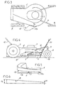
- the reference numeral 2 denotes the casing of a mower also constituting the chassis. This last one carries a heat engine 3, fixed on its part upper and with which the vertical shaft 4 (FIG. 4) is provided, at its end, means 5 for fixing a blade diametral 6 ensuring the cutting of the plants and arranged in all inside the housing. Housing 2 supports also two rear wheels 7, motorized or not, and two front wheels 8, via arms 9. In its rear part, it is used to fix a stretcher 10 and is provided with fixing means, not shown, for a removable collection basket 12. The housing is provided with a rear opening that can communicate with the basket collection and equipped with a shutter, not shown.
- the casing 2 comprises a front opening 13, the upper edge 14 of which is provided fixing means 15, such as nuts, or rods threaded, radially spaced for fixing two removable elements 16 and 17 allowing the modification of the function of the device, i.e. give it a mower function or mower function.
- Element 16 consists of a semi-circular cover which covers the entire opening 13, while element 17 is constituted by a deflector fixing on the upper edge of the rear part of the opening 13 which is downstream from the direction of rotation 21 of the blade 6.
- the opening 13 extends over an angle c having a value of at least 120 °, and which in this embodiment is 180 °.
- This opening is asymmetrical relative to the longitudinal median plane Pl of the machine. More precisely, the edge 13a, which is upstream with respect to the direction of rotation of the blade, represented by the arrow 21, is in front with respect to the transverse median plane Pt of the device, of an angular value a , while that the downstream edge 13b is behind this median plane Pt by an angular value b .
- the angular values a and b are of the order of 20 to 30 °.
- Figures 4 to 6 show that the height of the opening 13 increases from the upstream edge 13a up to the downstream edge 13b from a value H1 to a value H2, shown in Figure 6, H2 being between 2 and 5 times H1.
- the deflector 17 is composed of a lug of attachment 17a and a wall 17b projecting radially towards the outside by tipping down with a slope of the order of 15 °. This wall is provided, at its free end, of a return 17c, bent downwards.
- the tab 17a is provided with perforations 18 serving either for passage of screws screwed into nuts fixed on the casing 2 and constituting fixing means 15, ie at passage of the threaded rods fixed on the housing to constitute these fixing means and protruding from the tab to receive a nut.
- the cover 16 is crossed by perforations 19 cooperating with the fixing means 15.
- cover 16 is fixed on the edge 14 of the casing 15, so as to completely seal opening 13.
- the mower can be used with its rear flap down or with its rear flap raised, case in which the waste is ejected into the basket 12.
- the increase in height of the opening 13 prevents the rods 20 from getting stuck under the casing and therefore prevents jams requiring stopping the advancement and even the functioning of the mower.
- the deflector 17 also provides protection of the operator by limiting rearward projections, it being specified that, in the mower position, the flap 3 disposed at the rear of the casing 2 is also maintained in lowered position to oppose any projection towards the operator.
- the wheels rear 7 of the mower have a diameter larger than that of traditional mowers, and for example about 20 to 30 cm, and this to facilitate the moving the device in difficult terrain when it is in the mower position.
- the front wheels 8 are freely mounted in rotation at the end of arm 9 which, in the vertical plane, and as shown in Figures 1 and 4, are shaped like a swan neck and which in the plane horizontal, and as shown in Figures 2 and 3, form a "V" whose wings are spaced and diverge forward to allow passage of a large volume up to housing 2.
Abstract
Description
L'invention est relative aux appareils utilisés pour tondre, faucher, débroussailler et comportant une lame rotative calée sur l'arbre vertical d'un moteur thermique, ce moteur étant porté par un carter muni de roues et enveloppant la lame.The invention relates to the devices used for mowing, mowing, brush cutting and having a rotary blade fixed on the vertical shaft of a motor thermal, this engine being carried by a casing provided with wheels and wrapping the blade.
Dans les tondeuses, le carter est fermé sur l'avant et sur les côtés et est muni d'une ouverture arrière d'éjection, en général associée à un volet qui, lorsqu'il est ouvert, permet à l'herbe coupée de venir dans un panier amovible de collecte.In mowers, the housing is closed on front and sides and has an opening rear ejection, generally associated with a flap which, when open, allows cut grass to come in a removable collection basket.
Lorsque les herbes et végétaux sont très hauts, et possèdent des tiges plus résistantes, la coupe s'effectue mal et provoque des bourrages perturbant la tonte et la collecte.When the herbs and plants are very tall, and have more resistant stems, the cutting is carried out and causes jams disrupting mowing and collection.
Le brevet belge 688 778 décrit une tondeuse faucheuse dont le carter protecteur de la lame est, dans sa partie frontale, en retrait par rapport à la lame, et comporte une ouverture pour le passage de cette lame. Pour la fonction tondeuse, la lame dépassant du carter est protégée par un capot amovible, tandis que pour la fonction faucheuse débroussailleuse ce capot est enlevé pour permettre à la lame rotative de couper les tiges des végétaux ayant leur contact avec le carter. Cette configuration étant dangereuse, il faut ajouter à l'avant du carter un bouclier relevable de sécurité.Belgian patent 688,778 describes a mower mower with a protective blade guard in its front part, set back from the blade, and has an opening for the passage of this blade. For mower function, the blade protruding from the housing is protected by a removable cover, while for the brushcutter mower function this cover is removed to allow the rotary blade to cut the stems of the plants having their contact with the housing. This configuration being dangerous, add to the front of the casing a lifting safety shield.
La présente invention a pour objet de fournir une tondeuse multifonctions pouvant être utilisée pour la coupe des gazons et pour la coupe des herbes hautes, en supprimant dans la fonction tondeuse-débrousailleuse les bourrages et tous dangers pour le jardinier.The object of the present invention is to provide a multifunctional mower that can be used for cutting lawns and cutting tall grass, in removing in the mower-brushcutter function the jams and all dangers for the gardener.
A cet effet, dans la tondeuse selon l'invention, l'ouverture frontale du carter, d'une part, s'étend entre un bord amont, disposé en avant du plan médian transversal de la tondeuse, et un bord aval, disposé en arrière de ce même plan, et, d'autre part, présente une hauteur allant en croissant du bord amont jusqu'au bord aval, tandis que les éléments amovibles comprennent, pour la fonction tondeuse, un capot semi-circulaire, obturant toute l'ouverture, et pour la fonction faucheuse, un déflecteur disposé sur le bord supérieur de la partie aval de l'ouverture.To this end, in the mower according to the invention, the front opening of the casing, on the one hand, extends between an upstream edge, disposed in front of the transverse median plane of the mower, and a downstream edge, disposed behind this same plane, and, on the other hand, has a height ranging increasing from the upstream edge to the downstream edge, while removable elements include, for function trimmer, a semicircular hood, closing all the opening, and for the mowing function, a deflector arranged on the upper edge of the downstream part of the opening.
Pour transformer la tondeuse en faucheuse, il suffit donc de retirer le capot et de le remplacer par le déflecteur. Dans cette configuration, l'ouverture est dégagée sur la plus grande partie de sa longueur, ce qui permet, lors de l'avancement de l'appareil sur un front d'herbes hautes, de courber les tiges de ces herbes vers l'avant en amenant leurs parties inférieures sous le carter et dans la trajectoire de la lame rotative pour en favoriser le sectionnement. Les herbes, ainsi coupées, sont entraínées par la lame jusqu'au déflecteur qui les couche latéralement sur le côté en formant un andain.To transform the mower into a mower, it So just remove the cover and replace it with the deflector. In this configuration, the opening is clear over most of its length, which allows, when advancing the device on a front tall grass, bending the stems of these grasses towards the front by bringing their lower parts under the housing and in the path of the rotary blade to promote sectioning. The herbs, thus cut, are driven by the blade to the deflector which layer laterally on the side forming a swath.
Avantageusement, les roues avant sont montées libres en rotation à l'extrémité avant de bras qui, en forme de col de cygne dans le plan vertical, forment, dans le plan horizontal, un "V" dont les ailes sont espacées et divergent vers l'avant.Advantageously, the front wheels are mounted free to rotate at the forearm end which, in swan neck shape in the vertical plane, form, in the horizontal plane, a "V" whose wings are spaced and diverge forward.
Cette organisation des roues permet le passage entre elles d'une masse importante d'herbes hautes et favorise donc le fauchage de celles-ci.This organization of the wheels allows the passage between them a large mass of tall grass and therefore promotes mowing of these.
D'autres caractéristiques et avantages
ressortiront de la description qui suit en référence au
dessin schématique annexé représentant, à titre d'exemple,
une forme d'exécution de cette tondeuse.
Dans ce dessin, la référence numérique 2 désigne
le carter d'une tondeuse constituant également châssis. Ce
dernier porte un moteur thermique 3, fixé sur sa partie
supérieure et dont l'arbre vertical 4 (figure 4) est muni,
à son extrémité, de moyens de fixation 5 d'une lame
diamétrale 6 assurant la coupe des végétaux et disposée en
totalité à l'intérieur du carter. Le carter 2 supporte
également deux roues arrière 7, motorisées ou non, et deux
roues avant 8, par l'intermédiaire de bras 9. Dans sa
partie arrière, il sert à la fixation d'un brancard 10 et
est muni de moyens de fixation, non représentés, pour un
panier amovible de collecte 12. Le carter est muni d'une
ouverture arrière pouvant communiquer avec le panier de
collecte et équipée d'un volet, non représenté.In this drawing, the
Selon l'invention, le carter 2 comporte une
ouverture frontale 13 dont le bord supérieur 14 est muni
de moyens de fixation 15, tels qu'écrous, ou tiges
filetées, espacés radialement servant à la fixation de
deux éléments amovibles 16 et 17 permettant de modifier la
fonction de l'appareil, c'est à dire de lui donner une
fonction de tondeuse ou une fonction de faucheuse.
L'élément 16 est constitué par un capot semi circulaire
qui recouvre la totalité de l'ouverture 13, tandis que
l'élément 17 est constitué par un déflecteur se fixant sur
le bord supérieur de la partie arrière de l'ouverture 13
qui est en aval par rapport au sens de rotation 21 de la
lame 6.According to the invention, the
Comme le montre plus en détails la figure 2,
l'ouverture 13 s'étend sur un angle c ayant une valeur
d'au moins 120°, et qui dans cette forme d'exécution est
de 180°. Cette ouverture est dissymétrique par rapport au
plan médian longitudinal Pl de la machine. Plus
précisément, le bord 13a, qui est en amont par rapport au
sens de rotation de la lame, représentée par la flèche 21,
est en avant par rapport au plan médian transversal Pt de
l'appareil, d'une valeur angulaire a, tandis que le bord
aval 13b est en arrière par rapport à ce plan médian Pt
d'une valeur angulaire b. Les valeurs angulaires a et b
sont de l'ordre de 20 à 30°.As shown in more detail in Figure 2, the
Les figures 4 à 6 montrent que la hauteur de
l'ouverture 13 va en croissant depuis le bord amont 13a
jusqu'au bord aval 13b d'une valeur H1 à une valeur H2,
montré figure 6, H2 étant compris entre 2 et 5 fois H1.Figures 4 to 6 show that the height of
the
Le déflecteur 17 est composé d'une patte de
fixation 17a et d'une paroi 17b saillant radialement vers
l'extérieur en allant en s'inclinant vers le bas avec une
pente de l'ordre de 15°. Cette paroi est munie, à son
extrémité libre, d'un retour 17c, coudé vers le bas. La
patte 17a est munie de perforations 18 servant soit au
passage de vis se vissant dans des écrous fixés sur le
carter 2 et constituant moyens de fixation 15, soit au
passage des tiges filetées fixées sur le carter pour
constituer ces moyens de fixation et dépassant de la patte
pour recevoir un écrou.The
De même, le capot 16 est traversé par des
perforations 19 coopérant avec les moyens de fixation 15.Likewise, the
Comme montré à la figure 2, lorsque la tondeuse
est en configuration de tondeuse, le capot 16 est fixé sur
le bord 14 du carter 15, de manière à obturer totalement
l'ouverture 13. Dans cette configuration, la tondeuse peut
être utilisée avec son volet arrière abaissé ou avec son
volet arrière relevé, cas dans lequel les déchets sont
éjectés dans le panier 12.As shown in Figure 2, when the mower
is in mower configuration,
Pour amener la tondeuse dans sa configuration de
faucheuse, il faut retirer le capot 16 et mettre en place
le déflecteur 17 sur la partie arrière ou aval, de
l'ouverture 13, comme montré aux figures 3 et 4. Dans ces
conditions, lorsque la tondeuse est déplacée, le bord 14
de son carter vient en contact avec la tige 20 des
végétaux en les pliant sur l'avant, comme montré à la
figure 4, ce qui permet aux parties inférieures des tiges
de venir sous le carter 2 dans la trajectoire de la lame
6. La rotation de la lame amène les tiges coupées contre
le déflecteur 17 qui, par son inclinaison et son retour
coudé 17b, les couchent sur le sol en formant un andain.To bring the mower in its configuration of
mower, remove
Il faut ici noter que l'augmentation de la hauteur
de l'ouverture 13 évite aux tiges 20 de se coincer sous le
carter et empêche donc les bourrages nécessitant d'arrêter
l'avancement et voire même le fonctionnement de la
faucheuse. Le déflecteur 17 assure également la protection
de l'opérateur en limitant les projections vers l'arrière,
étant précisé que, en position de faucheuse, le volet 3
disposé à l'arrière du carter 2 est également maintenu en
position abaissée pour s'opposer à toute projection vers
l'opérateur.It should be noted here that the increase in height
of the
Dans la forme d'exécution représentée, les roues
arrière 7 de la tondeuse ont un diamètre plus grand que
celui des tondeuses traditionnelles, et par exemple de
l'ordre de 20 à 30 cm, et ceci pour faciliter le
déplacement de l'appareil, en terrain difficile, lorsqu'il
est en position de faucheuse. Les roues avant 8 sont
montées libres en rotation à l'extrémité de bras 9 qui,
dans le plan vertical, et comme montré aux figures 1 et 4,
sont en forme de col de cygne et qui, dans le plan
horizontal, et comme montré aux figures 2 et 3, forment un
"V" dont les ailes sont espacées et divergent vers l'avant
pour permettre le passage d'un volume important jusqu'au
carter 2.In the embodiment shown, the wheels
rear 7 of the mower have a diameter larger than
that of traditional mowers, and for example
about 20 to 30 cm, and this to facilitate the
moving the device in difficult terrain when it
is in the mower position. The
Il ressort de ce qui précède que par un aménagement simple, peu onéreux et de mise en place aisée, la tondeuse peut être rapidement transformée en faucheuse ou inversement, tout en restant sans danger pour l'utilisateur et permettre le débroussaillage sans risque de bourrage.It follows from the above that by a simple, inexpensive and easy to set up, the mower can be quickly transformed into a mower or vice versa, while remaining safe for the user and allow clearing without risk stuffing.
Claims (3)
- A multi-function mower comprising a housing (2) on wheels (7, 8), a rotary blade (6) arranged below the housing, and a thermal motor (3) which is arranged on the housing and the vertical shaft of which carries the blade (6), the said housing being provided with a front opening (13) and with fixing means (15) for detachable parts (16, 17) corresponding to the mowing function or the reaping function, characterised in that the front opening (13) of the housing on the one hand extends between an upstream edge (13a) arranged in front of the transverse central plane of the mower, and a downstream edge (13b) arranged behind the same plane, and on the other hand has a height which increases from the upstream edge (13a) to the downstream edge (13b), while the detachable parts comprise, for the mowing function, a semi-circular cover (16) closing the entire opening (13) and, for the reaping function, a deflector (17) arranged on the upper edge of the downstream portion of the opening (13).
- A mower according to claim 1, characterised in that the deflector (17) comprises a flange (17a) for fixing to the upper edge of the opening (13), a wall (17b) projecting radially outwards and inclined downwards, and a return (17c) bent downwards and arranged at the free end of this wall (17b).
- A mower according to claim 1, characterised in that the front wheels (8) are mounted so as to be freely rotatable on the front end of arms (9) which are swan-necked in the vertical plane and, in the horizontal plane, form a "V", the limbs of which are spaced apart and diverge towards the front.
Applications Claiming Priority (2)
| Application Number | Priority Date | Filing Date | Title |
|---|---|---|---|
| FR9710173 | 1997-08-04 | ||
| FR9710173A FR2766657B1 (en) | 1997-08-04 | 1997-08-04 | MULTIFUNCTIONAL MOWER |
Publications (2)
| Publication Number | Publication Date |
|---|---|
| EP0895710A1 EP0895710A1 (en) | 1999-02-10 |
| EP0895710B1 true EP0895710B1 (en) | 2002-11-06 |
Family
ID=9510160
Family Applications (1)
| Application Number | Title | Priority Date | Filing Date |
|---|---|---|---|
| EP98420132A Expired - Lifetime EP0895710B1 (en) | 1997-08-04 | 1998-07-24 | Multifunctional mower |
Country Status (4)
| Country | Link |
|---|---|
| EP (1) | EP0895710B1 (en) |
| AT (1) | ATE227066T1 (en) |
| DE (1) | DE69809151T2 (en) |
| FR (1) | FR2766657B1 (en) |
Families Citing this family (1)
| Publication number | Priority date | Publication date | Assignee | Title |
|---|---|---|---|---|
| JP4455236B2 (en) * | 2004-09-02 | 2010-04-21 | 本田技研工業株式会社 | Lawn mower |
Family Cites Families (8)
| Publication number | Priority date | Publication date | Assignee | Title |
|---|---|---|---|---|
| US2017524A (en) * | 1933-09-08 | 1935-10-15 | Harry W Bolens | Power operated mower |
| US3375645A (en) * | 1965-06-04 | 1968-04-02 | Locke Mfg Companies Inc | Lawn mower |
| BE688778A (en) * | 1966-10-24 | 1967-03-31 | ||
| US3496707A (en) * | 1968-01-15 | 1970-02-24 | Philip B Kobey | Hinged rotary mower housing |
| US4277937A (en) * | 1979-08-13 | 1981-07-14 | Luick Woodrow W | Convertible rotary mower-vacuum sweeper |
| FR2509568A1 (en) * | 1981-07-20 | 1983-01-21 | Daloz Jacques | Lawn mower with horizontal rotary blade - has blade mounted in housing with retractable front section moving to expose blade edge |
| US4466235A (en) * | 1983-01-10 | 1984-08-21 | Cole Denver C | Rotary mower |
| FR2737384B1 (en) * | 1995-08-02 | 1998-01-09 | Daloz Ets | HOUSING HOUSING |
-
1997
- 1997-08-04 FR FR9710173A patent/FR2766657B1/en not_active Expired - Fee Related
-
1998
- 1998-07-24 EP EP98420132A patent/EP0895710B1/en not_active Expired - Lifetime
- 1998-07-24 DE DE69809151T patent/DE69809151T2/en not_active Expired - Lifetime
- 1998-07-24 AT AT98420132T patent/ATE227066T1/en not_active IP Right Cessation
Also Published As
| Publication number | Publication date |
|---|---|
| EP0895710A1 (en) | 1999-02-10 |
| DE69809151D1 (en) | 2002-12-12 |
| FR2766657B1 (en) | 1999-09-03 |
| ATE227066T1 (en) | 2002-11-15 |
| FR2766657A1 (en) | 1999-02-05 |
| DE69809151T2 (en) | 2003-08-21 |
Similar Documents
| Publication | Publication Date | Title |
|---|---|---|
| FR2688150A1 (en) | APPARATUS FOR TRANSFORMING TREE BRANCHES INTO SMALL PIECES | |
| FR2567711A1 (en) | MOTOR LAWN MOWER | |
| FR3013940A1 (en) | DEVICE FOR FASTENING KNIFE ON THE ROTOR OF A MOWER-BRUSHCUTTER | |
| FR2768300A1 (en) | LAWN MOWER COMPRISING A SAFETY DEVICE PREVENTING AGAINST ACCESS TO THE ROTATING CUTTING BLADE | |
| EP0622008B1 (en) | Mechanic rake for clearing, trimming, raking all kinds of grasses and various plants | |
| FR2679104A1 (en) | DEVICE FOR ENSURING THE COLLECTION AND STORAGE OF GRASS OR SIMILAR PRODUCTS MOUNTED ON A VEHICLE. | |
| EP0895710B1 (en) | Multifunctional mower | |
| FR2927765A1 (en) | GRASS PICKING DEVICE FOR A TURF MOWER. | |
| EP0064115B2 (en) | Mower-conditioner | |
| EP1190616B1 (en) | Mulching mower | |
| EP0456592B1 (en) | Collecting device for a lawn mower, provided with a removable bottom, allowing the cut grass to be deposited directly | |
| FR2609859A1 (en) | PROTECTION FOR ROTARY MOWER | |
| FR2564279A1 (en) | Undergrowth clearer or mower having an obstacle bypass device | |
| EP1922914A1 (en) | Lawnmower adapted for borders and raised edges | |
| EP0622010B1 (en) | Agricultural machine, especially a fodder windrower | |
| FR2733115A1 (en) | Rotary cutter for vegetation, | |
| FR2509568A1 (en) | Lawn mower with horizontal rotary blade - has blade mounted in housing with retractable front section moving to expose blade edge | |
| FR2685993A1 (en) | Machine for cutting plants, particularly forestry shredder | |
| FR3112058A1 (en) | Agricultural device with a cutter bar and a removable collector and agricultural machine comprising such a device | |
| FR2468289A1 (en) | Horizontal blade for electric or IC engine lawn mower - has flat central portion with upturned cutting ends | |
| BE565295A (en) | ||
| FR2637450A1 (en) | Device for retaining cut grass in the gathering container of a lawnmower | |
| FR2601549A1 (en) | DEVICE FOR SEPARATING FOR MOWER WITH ROTATING CUTTING PLATES ON VERTICAL AXES. | |
| FR2686031A1 (en) | Rotor with rotating cutters, and machine for cutting plants, particularly forestry shredder equipped with at least one such rotor | |
| FR2486355A1 (en) | LAWN MOWER |
Legal Events
| Date | Code | Title | Description |
|---|---|---|---|
| PUAI | Public reference made under article 153(3) epc to a published international application that has entered the european phase |
Free format text: ORIGINAL CODE: 0009012 |
|
| AK | Designated contracting states |
Kind code of ref document: A1 Designated state(s): AT BE DE ES FR GB |
|
| AX | Request for extension of the european patent |
Free format text: AL;LT;LV;MK;RO;SI |
|
| 17P | Request for examination filed |
Effective date: 19990802 |
|
| AKX | Designation fees paid |
Free format text: AT BE DE ES FR GB |
|
| RBV | Designated contracting states (corrected) |
Designated state(s): AT BE DE ES FR IT |
|
| GRAG | Despatch of communication of intention to grant |
Free format text: ORIGINAL CODE: EPIDOS AGRA |
|
| GRAG | Despatch of communication of intention to grant |
Free format text: ORIGINAL CODE: EPIDOS AGRA |
|
| GRAH | Despatch of communication of intention to grant a patent |
Free format text: ORIGINAL CODE: EPIDOS IGRA |
|
| 17Q | First examination report despatched |
Effective date: 20020425 |
|
| GRAH | Despatch of communication of intention to grant a patent |
Free format text: ORIGINAL CODE: EPIDOS IGRA |
|
| GRAA | (expected) grant |
Free format text: ORIGINAL CODE: 0009210 |
|
| AK | Designated contracting states |
Kind code of ref document: B1 Designated state(s): AT BE DE ES FR IT |
|
| PG25 | Lapsed in a contracting state [announced via postgrant information from national office to epo] |
Ref country code: AT Free format text: LAPSE BECAUSE OF FAILURE TO SUBMIT A TRANSLATION OF THE DESCRIPTION OR TO PAY THE FEE WITHIN THE PRESCRIBED TIME-LIMIT Effective date: 20021106 |
|
| REF | Corresponds to: |
Ref document number: 227066 Country of ref document: AT Date of ref document: 20021115 Kind code of ref document: T |
|
| REF | Corresponds to: |
Ref document number: 69809151 Country of ref document: DE Date of ref document: 20021212 |
|
| PG25 | Lapsed in a contracting state [announced via postgrant information from national office to epo] |
Ref country code: ES Free format text: LAPSE BECAUSE OF FAILURE TO SUBMIT A TRANSLATION OF THE DESCRIPTION OR TO PAY THE FEE WITHIN THE PRESCRIBED TIME-LIMIT Effective date: 20030529 |
|
| PG25 | Lapsed in a contracting state [announced via postgrant information from national office to epo] |
Ref country code: BE Free format text: LAPSE BECAUSE OF NON-PAYMENT OF DUE FEES Effective date: 20030731 |
|
| PLBE | No opposition filed within time limit |
Free format text: ORIGINAL CODE: 0009261 |
|
| STAA | Information on the status of an ep patent application or granted ep patent |
Free format text: STATUS: NO OPPOSITION FILED WITHIN TIME LIMIT |
|
| 26N | No opposition filed |
Effective date: 20030807 |
|
| BERE | Be: lapsed |
Owner name: ETS *DALOZ Effective date: 20030731 |
|
| REG | Reference to a national code |
Ref country code: FR Ref legal event code: CJ Ref country code: FR Ref legal event code: CD |
|
| REG | Reference to a national code |
Ref country code: FR Ref legal event code: PLFP Year of fee payment: 19 |
|
| REG | Reference to a national code |
Ref country code: FR Ref legal event code: PLFP Year of fee payment: 20 |
|
| PGFP | Annual fee paid to national office [announced via postgrant information from national office to epo] |
Ref country code: IT Payment date: 20170703 Year of fee payment: 20 Ref country code: DE Payment date: 20170714 Year of fee payment: 20 Ref country code: FR Payment date: 20170726 Year of fee payment: 20 |
|
| REG | Reference to a national code |
Ref country code: DE Ref legal event code: R071 Ref document number: 69809151 Country of ref document: DE |