EP0064115B2 - Mower-conditioner - Google Patents
Mower-conditioner Download PDFInfo
- Publication number
- EP0064115B2 EP0064115B2 EP81400717A EP81400717A EP0064115B2 EP 0064115 B2 EP0064115 B2 EP 0064115B2 EP 81400717 A EP81400717 A EP 81400717A EP 81400717 A EP81400717 A EP 81400717A EP 0064115 B2 EP0064115 B2 EP 0064115B2
- Authority
- EP
- European Patent Office
- Prior art keywords
- hood
- conditioning
- rotor
- edge
- reaping
- Prior art date
- Legal status (The legal status is an assumption and is not a legal conclusion. Google has not performed a legal analysis and makes no representation as to the accuracy of the status listed.)
- Expired
Links
Images
Classifications
-
- A—HUMAN NECESSITIES
- A01—AGRICULTURE; FORESTRY; ANIMAL HUSBANDRY; HUNTING; TRAPPING; FISHING
- A01D—HARVESTING; MOWING
- A01D43/00—Mowers combined with apparatus performing additional operations while mowing
- A01D43/10—Mowers combined with apparatus performing additional operations while mowing with means for crushing or bruising the mown crop
- A01D43/102—Bruising control devices
Definitions
- the present invention relates to mower-conditioners of the type used to cut and condition harvest products, such as grass or fodder.
- Known mower-conditioners generally comprise a chassis intended to be coupled to a towing vehicle and on which is mounted a cutter bar which may be of the blade type, but which is often found in modern mower-conditioners of a type comprising a a number of discs or spinning tops rotating in pairs in opposite directions to cut the standing crop products.
- this cutter bar is surmounted towards its rear part of a conditioning rotor constituted by teeth, fingers or the like mounted on a shaft oriented transversely to the direction of advance of the machine, this rotor being combined with a packaging hood which has the effect of guiding the harvested products cut during their packaging, causing them to pass backwards above the rotor and ensuring, under the effect of the rotor, their rearward projection of the mower-conditioner, to form a swath.
- a conditioning rotor constituted by teeth, fingers or the like mounted on a shaft oriented transversely to the direction of advance of the machine
- the object of the invention is to create a mower-conditioner equipped with a conditioning hood arranged so as to allow, with particularly simple means and easy control, the adjustment of this hood relative to the rotor.
- the invention is embodied in a mower-conditioner according to the main claim.
- the threaded rod and the nut judiciously have an irreversible type of thread.
- the adjustment of the packaging cover relative to the ends of the fingers of the rotor can be ensured easily and quickly by rotation of the crank actuating the threaded rod, which thus displaces the associated nut and with it the element engaged with the corresponding edge of the cover. If the threads of the rod and of the nut are of the irreversible type, it is possible, if desired, not to provide a blocking or locking to retain the cover in the adjustment position obtained.
- the packaging covers of machines of this type are generally made of sheet metal which is often elastically deformable.
- an adjustment device of the type considered by the invention is provided for only one of the edges of the cover, the other edge can be connected to the body of the machine either pivotally or fixedly, the adjustment of the conditioning hood being effected in the latter case by elastic deformation of the sheet which constitutes it.
- the element engaged with the transverse edge of this cover has a length such that it extends over a significant distance, in particular over most of it. of the width of said packaging cover.
- the position of the adjustment device relative to the width of the cover can be chosen in any way, but said device will preferably be positioned so that the adjustment obtained is constant over the entire width of the cover.
- one possibility consists in providing the adjustment device towards the middle of the machine, the connection between the nut-forming part and the element for moving the conjugate edge being placed substantially in the middle of the packaging cover.
- this device on one side of the cover and provide a return extending to the other side, for joint control on both sides of the cover.
- Another solution is to provide such an adjustment device on each side of the cover, although the required means are then doubled, the adjustment position of each device must also be correctly identified.
- the displacement bar of the edge of the cover must be engaged in a fold of sheet metal of said cover, in a way thus making possible a certain relative movement during adjustment, this fold of sheet metal being able to be continuous or else formed by distributed receiving housings over the width of the cover and formed for example by legs curved or rolled from the sheet. Provision may also be made towards the adjustable edge of the cover for tabs provided with holes in which the adjusting element is engaged.
- the part forming a suitable nut on the threaded rod carrying the crank or the equivalent operating member is prevented from rotating with this threaded rod by a finger or the like engaged in a guide slot of a support. attached to the machine.
- this finger is then connected to the adjustment element of the conjugate edge of the cover, or else it itself forms, for example by its extension, this adjustment element.
- connection constituted by a bent lever half pivoted on the machine and connected by an arm.
- this finger provided on the nut and by its other arm to the hood edge adjustment element.
- this type is suitable for example for the adjustment of the lower edge of the packaging hood since the threaded rod and the crank are then placed vertically, which facilitates access and maneuvering, and obtaining by displacement a substantially displacement horizontal of the lower edge of the hood to bring it closer or away from the ends of the rotor fingers.
- connection can also be constituted by a simple link.
- the adjustment device makes it possible, by maneuvering the crank, to modify the position of the conditioning cover relative to the ends of the fingers of the rotor, for example by elastic deformation of the sheet of this cover, for the '' adapt to the working conditions each time encountered, with a view to obtaining optimum work. It is understood that this operation can be carried out quickly and simply by the driver of the tractor to which the mower-conditioner is coupled, without this operation requiring the use of a tool or any knowledge or skill on the part of the operator.
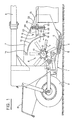
- Fig. is a schematic side view of a mower-conditioner to which the invention is applied.
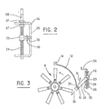
- Fig. is a view showing part of the adjustment device, looking in a direction perpendicular to that of FIG. 1.
- Fig. 3 is a partial schematic view corresponding to an alternative embodiment.
- FIG. 1 a mower-conditioner comprising a chassis 1 which is supported from the ground by rear wheels 2, this chassis being connected by a drawbar or a drawbar part of which is visible at 3 to a tractor vehicle which may be a tractor.
- the frame 1 carries a cutter bar generally designated by the reference 4, which in this case comprises a beam 5 on which are mounted rotary cutting discs 6 rotating in pairs in opposite directions in a manner per se known for cutting or mowing the harvested products on the field during the progress of the machine.
- the frame 1 also carries two side walls 7 between which is mounted a rotor generally designated by the reference 8, comprising in known manner a horizontal transverse shaft 9 which carries by means of flanges or hubs 10 teeth or fingers 11 connected to these articulated flanges, also in a manner known per se.
- a packaging cover indicated at 12 is provided on the machine between the side walls 7. This packaging cover surrounds as shown in FIG. the front part and the upper part of the conditioning rotor.
- a rear deflector 13 is also carried by the chassis 1 of the machine.
- the overall operation of a mower-conditioner of this type is well known.
- the products cut by the discs 6 of the cutter bar 4 move backwards above these discs 6 and are then taken up by the teeth or fingers 11 of the rotor 8, which is driven at high speed by suitable means (not shown) counterclockwise when looking at Fig. 1.
- the purpose of the cover 12 is to ensure, in combination with the teeth or fingers of the rotor 8, the packaging of the harvested products and to guide these products to pass them over this rotor, the said products then being sprayed towards the rear and being folded back onto the swathed ground by the rear deflector 13.
- the cover 12 is provided on its upper rear edge with fixing lugs 14 by which it is fixed to the side walls 7 of the machine body.
- This cover is also provided, towards its lower front edge, with a sheet metal fold 15 which extends over most of its width.
- An adjustment element constituted by a bar 16 is housed inside this sheet metal fold 15. It extends over the major part and judiciously over the entire width of the packaging cover 12.
- the bar 16 is formed from preferably two parts extending on either side of the lower end of the vertical arm 17 of a bent lever 18 pivotally mounted at 19 on the machine and whose horizontal arm 20 has a slot or slot of elongated shape 21 extending along the longitudinal axis of this arm 20 and by which said arm is engaged on a guide finger 22.
- the finger 22 is carried by a nut 23 which is engaged on a threaded rod 24.
- the end of the guide finger 22 also penetrates into a vertical slot 25 of a support 26 U-shaped which is fixed in any suitable way on the machine body.
- the threaded rod 24, which can rotate freely in the two horizontal branches of the U-shaped support 26, is immobilized axially with respect to this support as indicated in 27, and it carries a crank 28 at its upper end.
- the threads of the threaded rod 24 and the nut 23 are of the irreversible type.
- the adjustment is obtained by elastic deformation of the sheet forming said cover.
- the rear upper edge of the cover could be pivotally mounted relative to the side walls 7, which would allow adjustment without deformation.
- FIG.3 An alternative embodiment.
- the elements or parts corresponding to those visible in FIGS. 1 and 2 have been designated by the same references.
- the element 16 for adjusting the packaging cover which is here again fixed at 14 by its rear upper edge on the side walls 7 of the machine, is connected by a link 29 to the finger 22 carried by the 'nut 23.
- lugs 30 formed in this cover by folding the sheet or fixed on it by welding and provided with holes through which the adjusting element 16. This takes account of the fact that, during the rotation of the crank 28, the upward movement, for example, of the nut 23, transmitted by the finger 22 to the link 29, exerts an oblique traction in the direction of the high on this lower edge of the cover 12, as indicated by the arrow 31.
- the required adjustment of the packaging hood is obtained in a simple manner with a view to adapting it to the working conditions encountered.
- the device described can be provided for the lower edge of the packaging cover, or else for its upper edge, or even simultaneously for the two edges. In the latter case, it is possible to provide a control by separate crank for each of the edges or else, by means of suitable return members, simultaneous adjustment of these edges from the same crank.
Abstract
Description
La présente invention concerne les faucheuses-conditionneuses du type utilisé pour couper et conditionner des produits de récolte, tels que de l'herbe ou du fourrage.The present invention relates to mower-conditioners of the type used to cut and condition harvest products, such as grass or fodder.
Les faucheuses-conditionneuses connues comprennent généralement un châssis destiné à être attelé à un véhicule tracteur et sur lequel est montée une barre de coupe qui peut être du type à lame, mais qui est souvent dans les faucheuses-conditionneuses modernes d'un type comportant un certain nombre de disques ou toupies tournant par paires en sens opposés pour couper les produits de récolte sur pied. Dans un type de machines connu, cette barre de coupe est surmontée vers sa partie arrière d'un rotor de conditionnement constitué par des dents, des doigts ou des éléments analogues montés sur un arbre orienté transversalement à la direction d'avancement de la machine, ce rotor étant combiné à un capot de conditionnement qui a pour effet de guider les produits de récolte coupés pendant leur conditionnement, de provoquer leur passage vers l'arrière au-dessus du rotor et d'assurer, sous l'effet du rotor, leur projection vers l'arrière de la faucheuse-conditionneuse, pour former un andain.Known mower-conditioners generally comprise a chassis intended to be coupled to a towing vehicle and on which is mounted a cutter bar which may be of the blade type, but which is often found in modern mower-conditioners of a type comprising a a number of discs or spinning tops rotating in pairs in opposite directions to cut the standing crop products. In a known type of machine, this cutter bar is surmounted towards its rear part of a conditioning rotor constituted by teeth, fingers or the like mounted on a shaft oriented transversely to the direction of advance of the machine, this rotor being combined with a packaging hood which has the effect of guiding the harvested products cut during their packaging, causing them to pass backwards above the rotor and ensuring, under the effect of the rotor, their rearward projection of the mower-conditioner, to form a swath.
On sait que, pour obtenir un conditionnement approprié des produits, il est nécessaire de pouvoir régler la position du capot de conditionnement par rapport aux extrémités des dents ou doigts du rotor en fonction de la condition, notamment du degré d'humidité des produits de récolte, et de leur nature. On a proposé à cet effet, dans la technique antérieure, diverses solutions pour le réglage de ce capot. Un capot réglable de ce type est décrit par exemple dans la demande de brevet français FR-A 2 424 933.It is known that, in order to obtain appropriate packaging of the products, it is necessary to be able to adjust the position of the packaging hood relative to the ends of the teeth or fingers of the rotor as a function of the condition, in particular the degree of humidity of the harvested products. , and their nature. To this end, various solutions have been proposed in the prior art for adjusting this cover. An adjustable cover of this type is described for example in French patent application FR-A 2 424 933.
On a également proposé, dans US-A 3092946 l'emploi d'un mécanisme à tige filetée pour le réglage d'un capot.It has also been proposed, in US-A 3092946 the use of a threaded rod mechanism for adjusting a cover.
Le but de l'invention est de créer une faucheuse-conditionneuse équipée d'un capot de conditionnement agencé de façon à permettre, avec des moyens particulièrement simples et de commande aisée, le réglage de ce capot par rapport au rotor.The object of the invention is to create a mower-conditioner equipped with a conditioning hood arranged so as to allow, with particularly simple means and easy control, the adjustment of this hood relative to the rotor.
L'invention est matérialisée dans une faucheuse-conditionneuse selon la revendication principale.The invention is embodied in a mower-conditioner according to the main claim.
La tige filetée et l'écrou présentent judicieusement un filetage de type irréversible.The threaded rod and the nut judiciously have an irreversible type of thread.
Ainsi, le réglage du capot de conditionnement par rapport aux extrémités des doigts du rotor peut être assuré de façon aisée et rapide par rotation de la manivelle actionnant la tige filetée, qui déplace ainsi l'écrou associé et avec lui l'élément en prise avec le bord correspondant du capot. Si les filetages de la tige et de l'écrou sont de type irréversible, on peut si désiré ne pas prévoir de blocage ou verrouillage pour retenir le capot dans la position de réglage obtenue.Thus, the adjustment of the packaging cover relative to the ends of the fingers of the rotor can be ensured easily and quickly by rotation of the crank actuating the threaded rod, which thus displaces the associated nut and with it the element engaged with the corresponding edge of the cover. If the threads of the rod and of the nut are of the irreversible type, it is possible, if desired, not to provide a blocking or locking to retain the cover in the adjustment position obtained.
Les capots de conditionnement des machines de ce type sont généralement en tôle qui est souvent élastiquement déformable. Ainsi, lorsqu'un dispositif de réglage du type considéré par l'invention est prévu pour un seul des bords du capot, l'autre bord peut être relié au corps de la machine soit de façon pivotante, soit de façon fixe, le réglage du capot de conditionnement s'effectuant dans ce dernier cas par déformation élastique de la tôle qui le constitue. Mais il est bien entendu également possible de prévoir un tel dispositif de réglage en combinaison avec chacun des bords transversaux du capot de conditionnement.The packaging covers of machines of this type are generally made of sheet metal which is often elastically deformable. Thus, when an adjustment device of the type considered by the invention is provided for only one of the edges of the cover, the other edge can be connected to the body of the machine either pivotally or fixedly, the adjustment of the conditioning hood being effected in the latter case by elastic deformation of the sheet which constitutes it. However, it is of course also possible to provide such an adjustment device in combination with each of the transverse edges of the packaging cover.
Afin d'obtenir une position de réglage uniforme sur toute la largeur du capot de conditionnement, l'élément en prise avec le bord transversal de ce capot a une longueur telle qu'il s'étende sur une distance notable, notamment sur la majeure partie de la largeur dudit capot de conditionnement. La position du dispositif de réglage par rapport à la largeur du capot peut être choisie de façon quelconque, mais on positionnera de préférence ledit dispositif afin que le réglage obtenu soit constant sur toute la largeur du capot. Ainsi, une possibilité consiste à prévoir le dispositif de réglage vers le milieu de la machine, la liaison entre la pièce formant écrou et l'élément de déplacement du bord conjugué étant placée sensiblement au milieu du capot de conditionnement. Mais on pourrait également monter ce dispositif d'un côté du capot et prévoir un renvoi s'étendant jusqu'à l'autre côté, en vue d'une commande conjointe sur les deux côtés du capot. Une autre solution consiste à prévoir un tel dispositif de réglage de chaque côté du capot, bien que les moyens requis soient alors doublés, la position de réglage de chaque dispositif devant en outre être correctement repérée.In order to obtain a uniform adjustment position over the entire width of the packaging cover, the element engaged with the transverse edge of this cover has a length such that it extends over a significant distance, in particular over most of it. of the width of said packaging cover. The position of the adjustment device relative to the width of the cover can be chosen in any way, but said device will preferably be positioned so that the adjustment obtained is constant over the entire width of the cover. Thus, one possibility consists in providing the adjustment device towards the middle of the machine, the connection between the nut-forming part and the element for moving the conjugate edge being placed substantially in the middle of the packaging cover. But one could also mount this device on one side of the cover and provide a return extending to the other side, for joint control on both sides of the cover. Another solution is to provide such an adjustment device on each side of the cover, although the required means are then doubled, the adjustment position of each device must also be correctly identified.
La barre de déplacement du bord du capot doit être engagée dans un repli de tôle dudit capot, d'une manière rendant ainsi possible un certain mouvement relatif lors du réglage, ce repli de tôle pouvant être continu ou bien formé par des logements de réception répartis sur la largeur du capot et ménagés par exemple par des pattes recourbées ou roulées à partir de la tôle. On peut également prévoir vers le bord réglable du capot des pattes munies de trous dans lesquels l'élément de réglage est engagé.The displacement bar of the edge of the cover must be engaged in a fold of sheet metal of said cover, in a way thus making possible a certain relative movement during adjustment, this fold of sheet metal being able to be continuous or else formed by distributed receiving housings over the width of the cover and formed for example by legs curved or rolled from the sheet. Provision may also be made towards the adjustable edge of the cover for tabs provided with holes in which the adjusting element is engaged.
Suivant un mode de réalisation paraissant judicieux, la pièce formant écrou adaptée sur la tige filetée portant la manivelle ou l'organe de manoeuvre équivalent est empêchée de tourner avec cette tige filetée par un doigt ou analogue engagé dans une fente de guidage d'un support fixé sur la machine. Dans ce cas, ce doigt est alors relié à l'élément de réglage du bord conjugué du capot, ou bien il forme lui-même, par exemple par son prolongement, cet élément de réglage.According to an embodiment which seems judicious, the part forming a suitable nut on the threaded rod carrying the crank or the equivalent operating member is prevented from rotating with this threaded rod by a finger or the like engaged in a guide slot of a support. attached to the machine. In this case, this finger is then connected to the adjustment element of the conjugate edge of the cover, or else it itself forms, for example by its extension, this adjustment element.
Il est prévu, entrp le doigt ou l'élément analogue prévu sur l'écrou et l'élément en prise avec le bord du capot dQ"conditionnement, une liaison constituée par un levier coudé moité à pivotement sur la machine et relié par un bras à ce doigt prévu sur l'écrou et par son autre bras à l'élément de réglage du bord du capot. Un agencement de ce type est judicieux par exemple pour le réglage du bord inférieur du capot de conditionnement étant donné que l'on a alors disposé la tige filétée et la manivelle verticalement, ce qui facilite l'accès et la manoeuvre, et obtenir par renvoi un déplacement sensiblement horizontal du bord inférieur du capot pour le rapprocher ou l'écarter des extrémités des doigts du rotor.There is provided, between the finger or the similar element provided on the nut and the element engaged with the edge of the cover of the packaging, a connection constituted by a bent lever half pivoted on the machine and connected by an arm. to this finger provided on the nut and by its other arm to the hood edge adjustment element. this type is suitable for example for the adjustment of the lower edge of the packaging hood since the threaded rod and the crank are then placed vertically, which facilitates access and maneuvering, and obtaining by displacement a substantially displacement horizontal of the lower edge of the hood to bring it closer or away from the ends of the rotor fingers.
Mais la liaison précitée peut être constituée également par une simple biellette.However, the aforementioned connection can also be constituted by a simple link.
On voit ainsi que le dispositif de réglage suivant l'invention permet, par la manoeuvre de la manivelle, de modifier la position du capot de conditionnement par rapport aux extrémités des doigts du rotor, parexemple pardéformation élastique de la tôle de ce capot, pour l'adapter aux conditions de travail chaque fois rencontrées, en vue de l'obtention d'un travail optimum. On conçoit que cette opération peut être réalisée de manière rapide et simple par le conducteur du tracteur auquel la faucheuse-conditionneuse est attelée, sans que cette opération exige l'emploi d'un outil ou une connaissance ou habilité quelconque de la part de l'opérateur.It can thus be seen that the adjustment device according to the invention makes it possible, by maneuvering the crank, to modify the position of the conditioning cover relative to the ends of the fingers of the rotor, for example by elastic deformation of the sheet of this cover, for the '' adapt to the working conditions each time encountered, with a view to obtaining optimum work. It is understood that this operation can be carried out quickly and simply by the driver of the tractor to which the mower-conditioner is coupled, without this operation requiring the use of a tool or any knowledge or skill on the part of the operator.
La description qui va suivre, faite en ragard des dessins annexés, donnés à titre non limitatif, permettra de mieux comprendre l'invention.The description which follows, made with reference to the appended drawings, given without limitation, will allow a better understanding of the invention.
La Fig. est une vue schématique de profil d'une faucheuse-conditionneuse à laquelle l'invention est appliquée.Fig. is a schematic side view of a mower-conditioner to which the invention is applied.
La Fig. est une vue montrant une partie du dispositif de réglage, en regardant dans une direction perpendiculaire à celle de la Fig. 1.Fig. is a view showing part of the adjustment device, looking in a direction perpendicular to that of FIG. 1.
La Fig. 3 est une vue schématique partielle correspondant à une variante de réalisation.Fig. 3 is a partial schematic view corresponding to an alternative embodiment.
On a représenté schématiquement sur la Fig. 1 une faucheuse-conditionneuse comprenant un châssis 1 qui est supporté à partir du sol par des roues arrière 2, ce châssis étant relié par un timon ou une flèche d'attelage dont une partie est visible en 3 à un véhicule tracteur qui peut être un tracteur agricole.There is shown schematically in FIG. 1 a mower-conditioner comprising a
Le châssis 1 porte une barre de coupe désignée d'une façon générale par la référence 4, qui comprend dans le cas présent une poutre 5 sur laquelle sont montés des disques de coupe rotatifs 6 tournant par paires en sens opposés d'une manière en soi connue, pour couper ou faucher les produits de récolte sur le champ lors de la progression de la machine.The
Le châssis 1 porte également deux parois latérales 7 entre lesquelles est monté un rotor désigné d'une façon générale par la référence 8, comprenant de manière connue un arbre transversal horizontal 9 qui porte par l'intermédiaire de flasques ou moyeux 10 des dents ou doigts 11 reliés à ces flasques à articulation, également d'une manière en soi connue.The
Un capot de conditionnement indiqué en 12 est prévu sur la machine entre les parois latérales 7. Ce capot de conditionnement entoure comme montré sur la Fig. la partie avant et la partie supérieure du rotor de conditionnement. Un déflecteur arrière 13 est également porté par le châssis 1 de la machine.A packaging cover indicated at 12 is provided on the machine between the
Le fonctionnement d'ensemble d'une faucheuse-conditionneuse de ce type est bien connu. Les produits coupés par les disques 6 de la barre de coupe 4 se déplacent vers l'arrière au-dessus de ces disques 6 et sont alors repris par les dents ou doigts 11 du rotor 8, qui est entraîné à vitesse élevée par des moyens convenables (non représentés) dans le sens anti-horaire quand on regarde la Fig. 1. Le capot 12 a pour but d'assurer, en combinaison avec les dents ou doigts du rotor 8, le conditionnement des produits de récolte et de guider ces produits pour les faire passer au-dessus de ce rotor, lesdits produits étant alors projetés en direction de l'arrière et étant rabattus sur le sol en andain par le déflecteur arrière 13.The overall operation of a mower-conditioner of this type is well known. The products cut by the
Comme indiqué précédemment, on sait que pour obtenir un conditionnement approprié des produits de récolte, il est nécessaire de pouvoir adapter la position du capot de conditionnement par rapport au rotor, et plus spécialement la distance qui sépare ce capot des extrémités libres des doigts du rotor de conditionnement aux conditions de travail chaque fois recontrées et notamment au degré d'humidité et à la nature des produits de récolte fauchés et conditionnés.As indicated previously, it is known that in order to obtain an appropriate conditioning of the harvested products, it is necessary to be able to adapt the position of the conditioning hood relative to the rotor, and more especially the distance which separates this hood from the free ends of the fingers of the rotor. conditioning to the working conditions each time encountered and in particular to the degree of humidity and the nature of the mowed and conditioned crop products.
Suivant le mode de réalisation représenté sur la Fig. 1, le capot 12 est muni sur son bord supérieur arrière de pattes de fixation 14 par lesquelles il est fixé sur les parrois latérales 7 du corps de la machine. Ce capot est muni par ailleurs, vers son bord inférieur avant, d'un repli de tôle 15 qui s'étend sur la plus grande partie de sa largeur.According to the embodiment shown in FIG. 1, the
Un élément de réglage constitué par une barre 16 est logé à l'intérieur de ce repli de tôle 15. Il s'étend sur la majeure partie et judicieusement sur la totalité de la largeur du capot de conditionnement 12. La barre 16 est formée de préférence de deux parties s'étendant de part et d'autre de l'extrémité inférieure du bras vertical 17 d'un levier coudé 18 monté à pivotement en 19 sur la machine et dont le bras horizontal 20 présente une fente ou lumière de forme allongée 21 s'étendant selon l'axe longitudinal de ce bras 20 et par laquelle ledit bras est engagé sur un doigt de guidage 22.An adjustment element constituted by a
Comme cela est mieux visible sur la Fig.2, le doigt 22 est porté par un écrou 23 qui est engagé sur une tige filetée 24. L'extrémité du doigt de guidage 22 pénètre en outre dans une fente verticale 25 d'un support 26 en forme d'U qui est fixé de toute manière appropriée sur le corps de la machine. La tige filetée 24, qui peut tourner librement dans les deux branches horizontales du support en U 26, est immobilisée axialement par rapport à ce support comme indiqué en 27, et elle porte à son extrémité supérieure une manivelle 28. Les filetages de la tige filetée 24 et de l'écrou 23 sont de type irréversible.As is better visible in FIG. 2, the
Le mode d'utilisation du dispositif ainsi décrit se comprend aisément à la lecture de ce qui précède. Lorsque la position du capot de conditionnement 12 par rapport aux extrémités des doigts 11 doit être modifiée, la manivelle 28 est actionnée, ce que fait tourner la tige filetée 24 en provoquant en conséquence un déplacement vers la haut ou vers le bas de l'écrou 23, selon le sens de rotation. Cet écrou 23 est empêché de tourner avec la tige filetée 24 par le guidage du doigt 22 dans la fente 25 du support 26. Ce déplacement de l'écrou 23 fait basculer dans un sens ou dans l'autre le levier coudé 18 autour du point 19, ce qui provoque un déplacement sensiblement horizontal de l'élément de réglage 16 en prise avec le replie 15 de tôle du capot 12, pour la rapprocher ou l'écarter des extrémités des doigts 11.The mode of use of the device thus described is easily understood on reading the above. When the position of the
Suivant ce mode de réalisation, étant donné que le bord supérieur arrière du capot 12 est fixé en 14 sur les parois latérales 7, le réglage s'obtient par déformation élastique de la tôle formant ledit capot. Il va de soi toutefois que le bord supérieur arrière du capot pourrait être monté de façon pivotante par rapport aux parois latérales 7, ce qui permettrait un réglage sans déformation. Il va de soi également que l'on peut prévoir, en combinaison avec la manivelle et la tige filetée, des moyens de blocage dans la position chaque fois atteinte, ces moyens pouvant être constitués par un frein ou un varrou de type quelconque.According to this embodiment, since the rear upper edge of the
On a représenté sur la Fig.3 une variante de réalisation. Sur cette Fig. 3, les éléments ou parties correspondant à ceux visibles sur les Fig. 1 et 2 ont été désignés par les mêmes références.There is shown in Fig.3 an alternative embodiment. In this Fig. 3, the elements or parts corresponding to those visible in FIGS. 1 and 2 have been designated by the same references.
Suivant ce mode de réalisation, l'élément 16 de réglage du capot de conditionnement, qui est ici encore fixé en 14 par son bord supérieur arrière sur les parois latérales 7 de la machine, est relié par une biellette 29 au doigt 22 porté par l'écrou 23. Suivant cette variante de réalisation, il est prévu vers le bord inférieur avant du capot 12 des pattes 30 formées dans ce capot par repliage de la tôle ou fixées sur lui par soudage et munies de trous traversés par l'élément de réglage 16. Ceci tient compte du fait que, lors de la rotation de la manivelle 28, le déplacement vers le haut, par exemple, de l'écrou 23, transmit par le doigt 22 à la biellette 29, exerce une traction oblique en direction du haut sur ce bord inférieur du capot 12, comme indiqué par la flèche 31. On a indiqué par une flèche en 32 le déplacement subi par ce bord inférieur du capot 12 lorsqu'on fait tourner la manivelle 28 dans un sens qui déplace l'écrou 23 vers le bas. On comprend que, suivant ce mode de réalisation, le doigt 22 est engagé dans un trou correspondant de la biellette 29, et non pas dans une fente comme cela est le cas pour le levier coudé 18 représenté sur la Fig. 1.According to this embodiment, the
On voit qu'ici encore la rotation de la manivelle 28 déplace le bord inférieur du capot 12 d'une manière qui écarte ou rapproche ce capot des extrémités des doigts du rotor. Alors que, dans le cas du mode de réalisation que montre la Fig. 1, le réglage du bord inférieur du capot se limite à un déplacement sensiblement horizontal, ce qui réduit progressivement le degré de réglage entre le bord inférieur et le bord supérieur du capot, cette réduction est nettement moins prononcée dans le cas de la Fig. compte tenu de l'obliquité du déplacement du bord inférieur du capot 12 lors du réglage.It can be seen that here again the rotation of the
On comprend que, dans chacun des cas, on obtient d'une manière simple le réglage requis du capot de conditionnement en vue de son adaptation aux conditions de travail rencontrées. Comme indiqué précédemment, le dispositif décrit peut être prévu pour le bord inférieur du capot de conditionnement, ou bien pour son bord supérieur, ou encore simultanément pour les deux bords. Dans ce dernier cas, on peut prévoir une commande par manivelle séparée pour chacun des bords ou bien, grâce à des organes de renvoi appropriés, un réglage simultané des ces bords à partir d'une même manivelle.It will be understood that, in each case, the required adjustment of the packaging hood is obtained in a simple manner with a view to adapting it to the working conditions encountered. As indicated above, the device described can be provided for the lower edge of the packaging cover, or else for its upper edge, or even simultaneously for the two edges. In the latter case, it is possible to provide a control by separate crank for each of the edges or else, by means of suitable return members, simultaneous adjustment of these edges from the same crank.
Claims (8)
Priority Applications (7)
| Application Number | Priority Date | Filing Date | Title |
|---|---|---|---|
| DE198181400717T DE64115T1 (en) | 1981-05-06 | 1981-05-06 | MEASURING AND CONDITIONING DEVICE. |
| AT81400717T ATE10567T1 (en) | 1981-05-06 | 1981-05-06 | MOWING AND CONDITIONING DEVICE. |
| DE8181400717T DE3167560D1 (en) | 1981-05-06 | 1981-05-06 | Mower-conditioner |
| EP81400717A EP0064115B2 (en) | 1981-05-06 | 1981-05-06 | Mower-conditioner |
| ES511934A ES511934A0 (en) | 1981-05-06 | 1982-05-05 | "PERFECT MOWER CONDITIONER". |
| ZA823120A ZA823120B (en) | 1981-05-06 | 1982-05-06 | A mower-conditioner |
| DK203682A DK158816C (en) | 1981-05-06 | 1982-05-06 | forage harvesters |
Applications Claiming Priority (1)
| Application Number | Priority Date | Filing Date | Title |
|---|---|---|---|
| EP81400717A EP0064115B2 (en) | 1981-05-06 | 1981-05-06 | Mower-conditioner |
Publications (3)
| Publication Number | Publication Date |
|---|---|
| EP0064115A1 EP0064115A1 (en) | 1982-11-10 |
| EP0064115B1 EP0064115B1 (en) | 1984-12-05 |
| EP0064115B2 true EP0064115B2 (en) | 1988-12-28 |
Family
ID=8188516
Family Applications (1)
| Application Number | Title | Priority Date | Filing Date |
|---|---|---|---|
| EP81400717A Expired EP0064115B2 (en) | 1981-05-06 | 1981-05-06 | Mower-conditioner |
Country Status (6)
| Country | Link |
|---|---|
| EP (1) | EP0064115B2 (en) |
| AT (1) | ATE10567T1 (en) |
| DE (2) | DE3167560D1 (en) |
| DK (1) | DK158816C (en) |
| ES (1) | ES511934A0 (en) |
| ZA (1) | ZA823120B (en) |
Families Citing this family (10)
| Publication number | Priority date | Publication date | Assignee | Title |
|---|---|---|---|---|
| NL8400171A (en) * | 1984-01-19 | 1985-08-16 | Lely Nv C Van Der | SOIL TILLER. |
| DE3519669A1 (en) * | 1984-06-08 | 1986-01-23 | Osterrieder Gmbh Maschinenfabrik, 8941 Lautrach | Tedder for the treatment of grass, hay or the like |
| DE3446321A1 (en) * | 1984-12-19 | 1986-06-19 | Claas Saulgau GmbH, 7968 Saulgau | AGRICULTURAL EQUIPMENT FOR GRASS CONDITIONING |
| NL1006550C2 (en) * | 1997-07-11 | 1999-01-12 | Greenland Nieuw Vennep Bv | Crop harvesting machine with a bruising plate |
| FR2767633B1 (en) * | 1997-09-02 | 1999-10-08 | Kuhn Sa | IMPROVED CONDITIONING DEVICE, CONDITIONING MACHINE AND MOWER CONDITIONER COMPRISING SUCH A DEVICE |
| DE19826976A1 (en) * | 1998-06-18 | 1999-12-23 | Niemeyer Landmasch Gmbh | Conditioner for rotary mowers |
| FR2855012B1 (en) * | 2003-05-23 | 2006-06-02 | Kuhn Sa | FEED TREATING DEVICE WITH TWO GUIDING ELEMENTS |
| EP2656714A1 (en) | 2012-04-26 | 2013-10-30 | Macdon Industries Ltd | Pull-type crop harvesting machine transport system including a swath protection shield |
| US11925144B2 (en) * | 2021-01-22 | 2024-03-12 | Deere & Company | Mower conditioner impeller hood actuating mechanism |
| CN113079809B (en) * | 2021-04-09 | 2022-06-17 | 江苏杜林生态景观集团有限公司 | Afforestation is with afforestation trimming means |
Family Cites Families (4)
| Publication number | Priority date | Publication date | Assignee | Title |
|---|---|---|---|---|
| GB1010176A (en) * | 1962-06-12 | 1965-11-17 | Mathews B C | A rotary mower |
| DE1965749A1 (en) * | 1969-12-31 | 1971-07-08 | Kemper Kg Wilhelm | Haymaking machine with folding device |
| US4182099A (en) * | 1977-11-21 | 1980-01-08 | Deere & Company | Impeller mower-conditioner rotor |
| US4233803A (en) * | 1978-05-04 | 1980-11-18 | Deere & Company | Adjustable conditioning plate for an impeller mower-conditioner |
-
1981
- 1981-05-06 DE DE8181400717T patent/DE3167560D1/en not_active Expired
- 1981-05-06 AT AT81400717T patent/ATE10567T1/en not_active IP Right Cessation
- 1981-05-06 DE DE198181400717T patent/DE64115T1/en active Pending
- 1981-05-06 EP EP81400717A patent/EP0064115B2/en not_active Expired
-
1982
- 1982-05-05 ES ES511934A patent/ES511934A0/en active Granted
- 1982-05-06 DK DK203682A patent/DK158816C/en not_active IP Right Cessation
- 1982-05-06 ZA ZA823120A patent/ZA823120B/en unknown
Also Published As
| Publication number | Publication date |
|---|---|
| ATE10567T1 (en) | 1984-12-15 |
| DE3167560D1 (en) | 1985-01-17 |
| DK158816B (en) | 1990-07-23 |
| DK203682A (en) | 1982-11-07 |
| DK158816C (en) | 1990-12-24 |
| ES8303882A1 (en) | 1983-02-16 |
| EP0064115A1 (en) | 1982-11-10 |
| ES511934A0 (en) | 1983-02-16 |
| EP0064115B1 (en) | 1984-12-05 |
| ZA823120B (en) | 1983-03-30 |
| DE64115T1 (en) | 1983-05-26 |
Similar Documents
| Publication | Publication Date | Title |
|---|---|---|
| EP0332552B1 (en) | Improvement for agricultural harvesting machines | |
| CA2226656C (en) | Perfected agricultural mowing machine | |
| EP0242311B1 (en) | Rotary mower provided with a cutting bar and a supporting structure | |
| EP1705980A1 (en) | Disc tiller soil working machine | |
| EP1055843B1 (en) | Belt tensioner | |
| EP0184533A1 (en) | Mowing machine with an intermediate structure and means to prevent the accumulation of crop material | |
| FR2749127A1 (en) | VEGETABLE CUTTING MACHINE FOR REACHING A MOTOR VEHICLE WITH A LOCKING DEVICE OF THE CUTTING MECHANISM | |
| FR2628596A1 (en) | MACHINE WITH DIRECT DRIVE | |
| EP0064115B2 (en) | Mower-conditioner | |
| EP0360716B1 (en) | Mower with improved skids | |
| EP0692185B1 (en) | Haymaking machine, especially a swather with controlled fork-carrying arms | |
| FR2577105A1 (en) | MOTORIZED TURF MOWER | |
| WO2000052992A1 (en) | Hay harvesting machine provided with at least a swathing rotor equipped with a deflector with adjustable position | |
| EP3054760B1 (en) | Haymaking machine with an improved ground surface following | |
| EP0064114B1 (en) | Mower-conditioner | |
| EP0070942B1 (en) | Compressing device for the pick-up of a harvesting machine | |
| EP0554200B1 (en) | Haymaking machine comprising a frame with controlled support wheels | |
| EP0517633B1 (en) | Improved mower | |
| EP0536071B1 (en) | Haymaking machine, especially a crop tedder, with at least two work positions | |
| EP1269826B1 (en) | Haymaking machine | |
| FR2687892A1 (en) | FORAGE BREEDER WITH A MECHANISM FOR INTERRUPTING ROTOR TRAINING. | |
| EP0442833B1 (en) | Haymaking machine with an improved safety device | |
| FR2519835A1 (en) | HITCHING DEVICE FOR A TRACTOR AGRICULTURAL INSTRUMENT | |
| FR2695796A1 (en) | Hay tedder with rotor bar on supporting wheels - has wheel position controlled during operation by traction and thrust bar between towbar stirrup and rear lever linked to regulating rod | |
| FR2553253A1 (en) | Swathe control for grass cutter |
Legal Events
| Date | Code | Title | Description |
|---|---|---|---|
| PUAI | Public reference made under article 153(3) epc to a published international application that has entered the european phase |
Free format text: ORIGINAL CODE: 0009012 |
|
| 17P | Request for examination filed |
Effective date: 19820416 |
|
| AK | Designated contracting states |
Designated state(s): AT BE CH DE FR GB IT LU NL SE |
|
| RBV | Designated contracting states (corrected) |
Designated state(s): AT CH DE FR GB LI NL SE |
|
| TCNL | Nl: translation of patent claims filed | ||
| TCAT | At: translation of patent claims filed | ||
| DET | De: translation of patent claims | ||
| GRAA | (expected) grant |
Free format text: ORIGINAL CODE: 0009210 |
|
| AK | Designated contracting states |
Designated state(s): AT CH DE FR GB LI NL SE |
|
| REF | Corresponds to: |
Ref document number: 10567 Country of ref document: AT Date of ref document: 19841215 Kind code of ref document: T |
|
| REF | Corresponds to: |
Ref document number: 3167560 Country of ref document: DE Date of ref document: 19850117 |
|
| PLBI | Opposition filed |
Free format text: ORIGINAL CODE: 0009260 |
|
| 26 | Opposition filed |
Opponent name: C. VAN DER LELY N.V. Effective date: 19850904 |
|
| NLR1 | Nl: opposition has been filed with the epo |
Opponent name: C. VAN DER LELY N.V. |
|
| REG | Reference to a national code |
Ref country code: CH Ref legal event code: PL |
|
| PUAH | Patent maintained in amended form |
Free format text: ORIGINAL CODE: 0009272 |
|
| STAA | Information on the status of an ep patent application or granted ep patent |
Free format text: STATUS: PATENT MAINTAINED AS AMENDED |
|
| 27A | Patent maintained in amended form |
Effective date: 19881228 |
|
| AK | Designated contracting states |
Kind code of ref document: B2 Designated state(s): AT CH DE FR GB LI NL SE |
|
| NLR2 | Nl: decision of opposition | ||
| NLR3 | Nl: receipt of modified translations in the netherlands language after an opposition procedure | ||
| PG25 | Lapsed in a contracting state [announced via postgrant information from national office to epo] |
Ref country code: LI Free format text: LAPSE BECAUSE OF NON-PAYMENT OF DUE FEES Effective date: 19890531 Ref country code: CH Free format text: LAPSE BECAUSE OF NON-PAYMENT OF DUE FEES Effective date: 19890531 |
|
| PGFP | Annual fee paid to national office [announced via postgrant information from national office to epo] |
Ref country code: AT Payment date: 19920507 Year of fee payment: 12 |
|
| PGFP | Annual fee paid to national office [announced via postgrant information from national office to epo] |
Ref country code: SE Payment date: 19920515 Year of fee payment: 12 |
|
| PG25 | Lapsed in a contracting state [announced via postgrant information from national office to epo] |
Ref country code: AT Effective date: 19930506 |
|
| PG25 | Lapsed in a contracting state [announced via postgrant information from national office to epo] |
Ref country code: SE Effective date: 19930507 |
|
| PGFP | Annual fee paid to national office [announced via postgrant information from national office to epo] |
Ref country code: GB Payment date: 19940418 Year of fee payment: 14 |
|
| PGFP | Annual fee paid to national office [announced via postgrant information from national office to epo] |
Ref country code: FR Payment date: 19940516 Year of fee payment: 14 |
|
| PGFP | Annual fee paid to national office [announced via postgrant information from national office to epo] |
Ref country code: NL Payment date: 19940531 Year of fee payment: 14 |
|
| PGFP | Annual fee paid to national office [announced via postgrant information from national office to epo] |
Ref country code: DE Payment date: 19940622 Year of fee payment: 14 |
|
| EUG | Se: european patent has lapsed |
Ref document number: 81400717.5 Effective date: 19931210 |
|
| PG25 | Lapsed in a contracting state [announced via postgrant information from national office to epo] |
Ref country code: GB Effective date: 19950506 |
|
| PG25 | Lapsed in a contracting state [announced via postgrant information from national office to epo] |
Ref country code: NL Effective date: 19951201 |
|
| GBPC | Gb: european patent ceased through non-payment of renewal fee |
Effective date: 19950506 |
|
| NLV4 | Nl: lapsed or anulled due to non-payment of the annual fee |
Effective date: 19951201 |
|
| PG25 | Lapsed in a contracting state [announced via postgrant information from national office to epo] |
Ref country code: DE Effective date: 19960201 |
|
| PG25 | Lapsed in a contracting state [announced via postgrant information from national office to epo] |
Ref country code: FR Effective date: 19960229 |
|
| REG | Reference to a national code |
Ref country code: FR Ref legal event code: ST |
|
| REG | Reference to a national code |
Ref country code: FR Ref legal event code: ST |