EP0894939B1 - Unterwasser-Steigleitung mit mehrfach Spannzylinder mit kontrollierbarem Druck und dazugehöriges Verfahren - Google Patents
Unterwasser-Steigleitung mit mehrfach Spannzylinder mit kontrollierbarem Druck und dazugehöriges Verfahren Download PDFInfo
- Publication number
- EP0894939B1 EP0894939B1 EP98202608A EP98202608A EP0894939B1 EP 0894939 B1 EP0894939 B1 EP 0894939B1 EP 98202608 A EP98202608 A EP 98202608A EP 98202608 A EP98202608 A EP 98202608A EP 0894939 B1 EP0894939 B1 EP 0894939B1
- Authority
- EP
- European Patent Office
- Prior art keywords
- control
- fluid
- cylinder
- pressure
- riser
- Prior art date
- Legal status (The legal status is an assumption and is not a legal conclusion. Google has not performed a legal analysis and makes no representation as to the accuracy of the status listed.)
- Expired - Lifetime
Links
- 238000000034 method Methods 0.000 title claims 6
- 239000012530 fluid Substances 0.000 claims description 88
- 238000004891 communication Methods 0.000 claims description 37
- 239000007788 liquid Substances 0.000 claims description 21
- 238000006243 chemical reaction Methods 0.000 claims description 9
- 238000004873 anchoring Methods 0.000 claims 1
- 238000003780 insertion Methods 0.000 claims 1
- PEDCQBHIVMGVHV-UHFFFAOYSA-N Glycerine Chemical compound OCC(O)CO PEDCQBHIVMGVHV-UHFFFAOYSA-N 0.000 description 9
- XLYOFNOQVPJJNP-UHFFFAOYSA-N water Substances O XLYOFNOQVPJJNP-UHFFFAOYSA-N 0.000 description 6
- 238000010586 diagram Methods 0.000 description 5
- 239000003208 petroleum Substances 0.000 description 5
- 230000000694 effects Effects 0.000 description 4
- 230000009471 action Effects 0.000 description 3
- 238000005553 drilling Methods 0.000 description 3
- 230000009977 dual effect Effects 0.000 description 3
- 238000004519 manufacturing process Methods 0.000 description 3
- 239000006096 absorbing agent Substances 0.000 description 2
- 230000005484 gravity Effects 0.000 description 2
- 230000001105 regulatory effect Effects 0.000 description 2
- 230000006978 adaptation Effects 0.000 description 1
- 230000002411 adverse Effects 0.000 description 1
- 238000005452 bending Methods 0.000 description 1
- 230000006872 improvement Effects 0.000 description 1
- 239000002184 metal Substances 0.000 description 1
- 238000012986 modification Methods 0.000 description 1
- 230000004048 modification Effects 0.000 description 1
- 230000001681 protective effect Effects 0.000 description 1
- 238000005096 rolling process Methods 0.000 description 1
- 238000006467 substitution reaction Methods 0.000 description 1
Images





Classifications
-
- B—PERFORMING OPERATIONS; TRANSPORTING
- B63—SHIPS OR OTHER WATERBORNE VESSELS; RELATED EQUIPMENT
- B63B—SHIPS OR OTHER WATERBORNE VESSELS; EQUIPMENT FOR SHIPPING
- B63B21/00—Tying-up; Shifting, towing, or pushing equipment; Anchoring
- B63B21/50—Anchoring arrangements or methods for special vessels, e.g. for floating drilling platforms or dredgers
- B63B21/502—Anchoring arrangements or methods for special vessels, e.g. for floating drilling platforms or dredgers by means of tension legs
-
- E—FIXED CONSTRUCTIONS
- E21—EARTH OR ROCK DRILLING; MINING
- E21B—EARTH OR ROCK DRILLING; OBTAINING OIL, GAS, WATER, SOLUBLE OR MELTABLE MATERIALS OR A SLURRY OF MINERALS FROM WELLS
- E21B19/00—Handling rods, casings, tubes or the like outside the borehole, e.g. in the derrick; Apparatus for feeding the rods or cables
- E21B19/002—Handling rods, casings, tubes or the like outside the borehole, e.g. in the derrick; Apparatus for feeding the rods or cables specially adapted for underwater drilling
- E21B19/004—Handling rods, casings, tubes or the like outside the borehole, e.g. in the derrick; Apparatus for feeding the rods or cables specially adapted for underwater drilling supporting a riser from a drilling or production platform
- E21B19/006—Handling rods, casings, tubes or the like outside the borehole, e.g. in the derrick; Apparatus for feeding the rods or cables specially adapted for underwater drilling supporting a riser from a drilling or production platform including heave compensators
Definitions
- This invention relates to tensioning of seabed-to-vessel marine risers with a plurality of long pneumatic or hydraulic cylinders having controllable tension for deep-sea and storm-condition use in addition to shallow-water and all-weather use with ease of operation and high reliability.
- the invention relates to a riser tensioner as defined by the preamble of claim 1.
- a riser tensioner is described in US Patent Number 4,799,827, issued to Jaqua.
- a variety of means for tensioning risers are known for tensioning risers. The most common are cable-operated systems that have been developed for offshore activities but are too heavy, space-consuming, expensive and top-heavy for optimal deep-ocean petroleum vessels. Other known risers are basically resilience systems that employ various types of spring tension with erratically changeable tension and related problems resulting in high costs and limited deep-water capability. None are known to provide constancy of tension, long-length tensioning, effective positioning within a moon pool, low weight, economy, convenience, time-saving features, fire protectiveness and reliability with adjustably controlled tension in a manner taught by this invention. Deeper-ocean and stormier-weather operations are made economically feasible in addition to benefitting shallow offshore petroleum conditions similarly.
- Patent Number 4,808,035, issued to Stanton et al taught an elastomeric bellows as a gas spring for riser tensioning on a tension-leg platform.
- U.S. Patent Number 4,537,533, issued to Hampton taught riser tensioning with a heave compensator on- a hoisting apparatus that was used primarily for positioning seabed templates from a semi-submersible drill rig.
- Patent Number 4,379,657 issued to Widiner at al, was limited to a portable modular riser tensioner having at least two pairs of cylinders that are diametrically opposed with interconnected oil accumulators and air accumulators with positioning between a mounting frame and a riser tensioning ring for use on a tensioned-leg platform.
- U.S. Patent number 4,367,981 issued to Shapiro, taught a drilling riser having a "slip joint" with an annular pressure chamber between flanged portions of an upper end that was attachable to a drilling platform.
- objects of this invention are to provide a controlled-pressure multi-cylinder riser tensioner which:
- This invention accomplishes these and other objectives with a controlled-pressure multi-cylinder riser tensioner having a plurality of preferably six control cylinders with top ends attached pivotally to a bottom surface of an operational floor and bottom ends attached pivotally to a riser-tensioner ring.
- Pressure lines in communication with opposite ends of the control cylinders lead to accumulators and to sources of pressure that are separately controlled automatically.
- Stroke length of the control cylinders is typically 50 feet for normal requirements but can be varied for particular operational requirements. Projection of the cylinders downwardly into a moon pool avoids their obstruction of work space on an operational floor of a vessel.
- Positioning pneumatic and hydraulic machinery below deck with tubing leading to the control cylinders lowers center of gravity for ballast effect of a seaworthy deep-water vessel.
- Each cylinder can have a separate pressurization system for reliability redundancy.
- An over-capacity for tensioning the riser with a portion of the control cylinders inactive or incapacitated increases reliability.
- Pressure transducers communicate pressure-change criteria to a central control system for coordinated automatic or optionally manual control of fluid pressure for each control cylinder separately.
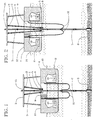
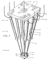
- FIGS. 1-2 A plurality of preferably six or more control-cylinder units 1 have proximal ends 2 attached pivotally proximate a bottom of an operational floor 3 on a marine vessel 4. Distal ends 5 of the control-cylinder units 1 are attached pivotally to a riser-tensioner ring 6 to which a marine riser 7 is attachable with linear rigidity.
- the marine riser 7 is affixed to a seabed 8 by cementing, marine templates or other means and extended vertically to working relationship to a moon pool 9 over which the operational floor 3 or other operational floor is positioned in working relationship to a marine drill rig or other marine equipment that are not illustrated.
- control-cylinder units 1 are provided with separately controllable pressurized control fluid in fluid communication from pressurization mechanization 10 that can be placed in support positions 11 that are low on the marine vessel 4 and do not interfere with working space either on the operational floor 3, on a deck 12 of the marine vessel 4 or in the moon pool 9.
- Pressurized control fluids in the control-cylinder units 1 provide selectively contractive pressures in directions from the distal ends 5 and towards the proximal ends 2 of the control-cylinder units 1 .
- Constantly controllable upward pressure prevents the marine riser 7 from bending, buckling, falling or escaping from a working position in the moon pool 9 from wave-generated positioning, from weather-generated positioning or from other positioning of the marine vessel 4 in a working mode.
- Expandable and contractible length of the pressurized control-cylinder units 1 is typically 50 feet. This is sufficient for most ocean-wave conditions. Longer operational length can be provided for continuously safe working in extreme weather conditions with adequately designed and structured marine vessels 4 . The most severe weather and wave conditions and the deepest oceans can be accommodated with this riser tensioner adapted to possibly V-bottomed, round-bottomed, multi-hulled or buoy-like marine vessels 4.
- a plurality of control-cylinder units 1 can be made to provide optimally lateral positioning of the marine riser 7 in working relationship to such items as drill stems, casing, drill-fluid connections and production lines that are placed in, conveyed through and removed from the marine riser 7 from a central position 15 on an operational floor 3. Lateral positioning is achieved by relative decrease of pressure in control-cylinder units 1 proximate edges of the moon pool 9 towards which lateral positioning is desired.
- the control-cylinder units 1 have piston rods 17 extendible selectively from cylinders 18.
- the piston rods 17 are attached pivotally with a ball-and-socket connection 19 to the riser-tensioner ring 6 at the distal end 5 and the cylinders 18 are attached with a ball-and-socket connection 19 to the operational floor 3 at the proximal ends 2 of the control-cylinder units 1.
- Pivotal connection of ends of the control-cylinder units 1 to the riser-tensioner ring 6 and/or to the bottom of the operational floor 3 can be with spherical bearings also in accordance with design preferences for particular use conditions.
- Fluid-pressure tubes 20 are routed to pressurized portions of the control-cylinder units 1 .
- pressurized portions of the control-cylinder units 1 are rod ends of the cylinders 18 where pressurized fluid forces pistons 21 on ends of the piston rods 17 upwardly to provide a lifting tension on the marine riser 7.
- riser-tensioner rings 6 can be used with this riser tensioner.
- the two portions of a split type of riser-tensioner ring 6 also can be hinged together on one side or attachable on both sides for different design preferences.
- Illustrative of fasteners generally for a split type of riser-tensioner ring 6 is a threaded fastener 24 shown in FIG. 4.
- a split type of riser-tensioner ring 6 allows quick connection and disconnection, which can be quicker yet with a quick-disconnect fastener of various types in place of the illustrative threaded fastener 24.
- a quick-disconnect fastener can be a type which does not separate from the riser-tensioner ring 6, such that it cannot fall into the ocean.
- the threaded fastener 24 is shown only to illustrate attachableness of the first ring half 22 to the second ring half 23. Thorough description of riser-tensioning rings 6 and fastening means for them are not included in this document.
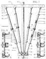
- FIG. 4 depicts top cylinders 25 joined pivotally to the operational floor 3 and bottom pistons 26 joined pivotally to the riser-tensioner ring 6. They are joined by an interconnecting rod 27 having a top piston 28 and a bottom piston 29 respectively.
- FIG. 7 depicts a top piston rod 30 attached pivotally to the operational floor 3 and a bottom piston rod 31 attached pivotally to the riser-tensioner ring 6.
- a top interconnected cylinder 32 has a top-cylinder piston 33 on the top piston rod 30.
- a bottom interconnected cylinder 34 has a bottom-cylinder piston 35 on the bottom piston rod 31 .
- FIG. 10 depicts a top piston rod 30, as shown in FIG.
- FIG. 11 depicts a top piston rod 30 attached pivotally to the operational floor 3 and a bottom piston 26 attached pivotally to the riser-tensioner ring 6 in opposite relationship to the FIG. 3 illustration.
- control-cylinder units 1 are foreseeable within the scope of this invention. However, the preferred type depicted in FIG. 3 can be structured appropriately for most applications and use conditions.
- fluid-pressure tubes 20 and fluid-return lines 38 can be structured appropriately for different types of control-cylinder units 1 , for different use conditions, for different pressure fluids and for different applications.
- fluid-pressure tubes 20 are shown at both ends of top cylinder 25 and bottom cylinder 26.
- Appropriate control valves, pressurization means, pressure accumulators, safety valves and conveyance tubes beyond ends of the fluid-pressure tubes 20 shown in these sectional drawings are assumed for particular pneumatic and hydraulic embodiments of this invention.
- fluid-pressure tubes 20 are shown at rod ends of top interconnected cylinder 32 and bottom interconnected cylinder 34 while fluid-return lines 38 are shown at interconnecting blind ends of the same cylinders 32 and 34.
- the fluid-return lines 38 are depicted as having pressure-relief valves, although this type of valve is only representative of pressure-release valves in general that can be operated with means other than a spring as depicted.
- fluid-pressure tubes 20 are shown at both ends of the top interconnected cylinder 32 and the bottom interconnected cylinder 34 to demonstrate selectiveness of combinations of components of different embodiments of the control-cylinder units 1 .
- fluid-pressure tubes 20 are positioned in fluid communication with piston-rod ends of the bottom cylinders 26 and the floating cylinders 37.
- Fluid-pressure tubes 20 Essential to positioning of fluid-pressure tubes 20 is direction of pressurized fluid through them to raise distal ends 5 of the control-cylinder units 1 vertically in order to provide vertically upward tension on the marine riser 7 controllably and selectively by raising and/or laterally positioning the riser-tensioner ring 6 to which the marine riser 7 is attached with linear rigidity.
- pressurized fluid is directed controllably into pressurized portions of cylinders 18, 25, 26, 32, 34 and/or 37, regardless of how or whether a fluid-return line 38 is employed for different types of pressurization fluids and applications of this invention.
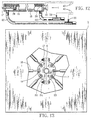
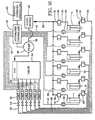
- pressure transducers 39 in pressure-indicative communication from pressurized portions of the control-cylinder units 1 have control-input lines 40 leading to an automated controller 41 shown in FIGS. 14-16.
- the pressure transducers 39 can be in pressure-indicative communication directly with pressurized portions of the control-cylinder units 1 and/or with fluid-pressure tubes 20 at positions in the fluid-pressure tubes 20 where pressure readings are not significantly different than at the control-cylinder units 1 directly.
- the automated controller 41 and the manual-override controller 42 are in proximity to and operated in relation to a driller's control panel with a plurality of operating stations throughout a vessel for safety redundance at select safety positions.
- the riser-tensioner ring 6 can be pressured vertically upward towards the operational floor 3 and from-side-to-side in any direction laterally in order to tension the marine riser 7 while maintaining it in a desired position centrally by appropriate pressurization of cylinders 18 from which piston rods 17 are extended to pivotal attachment to the riser-tensioner ring 6.
- the separately controllable means of supply of pressurized control fluid has an automated controller 41 with which supply of pressurized control fluid is directed through accumulators 49 to pressurized portions of control-cylinder units 1 at pressures and volumes to achieve select vertically upward tension on the riser 7 in controlled reaction to wave-generated positioning, weather-generated positioning and otherwise caused positioning of the marine vessel 4 in relationship to a length of tensioned marine riser 7 having a proximal end 2 that is attached to the riser-tensioner ring 6 and a distal end 5 that is affixed to a seabed 8.
- a manual-override controller 42 can be positioned at a local control panel to adjust and to override-control the automated controller 41.
- Control-input lines 40 can be employed to convey pressure data from pressure transducers 39, described also in relation to FIG. 12, for the automated controller 41 to determine pressure requirements for communication to centrally controlled valve units 43 to direct an appropriate- level of pressure and/or volume of pressurized control fluid through control-unit valves 44 for conveyance in fluid-pressure tubes 20 to pressurized portions of the control-cylinder units 1 .
- Control communication is conveyed from the automated controller 41 and/or the manual-override controller 42 to the centrally controlled valve units 43 through control-output lines 45.
- Controllably variable fluid volume at select pressures for effective riser tensioning can be supplied to the control-cylinder units 1 without pressure requirements being indicated by the pressure transducers 39 .
- the pressure transducers 39 can be used primarily to indicate emergency conditions such as a riser break that require special pressurization.
- a basic control loop without the pressure transducer is the same as indicated in FIGS. 13-16, however, because pressure and volume of fluid to be supplied are determined by pressure in the control-cylinder units 1 .
- a central pump 46 can be provided to pressurize a centralized-pressure accumulator 47 from which all pressurized control fluid in proportions directed by the automated controller 41 for release into fluid-pressure tubes 20 by the centrally controlled valve units 43 through control-unit valves 44.
- a fluid-supply source 48 can be provided for supply of fluid to the central pump 46 .
- Input accumulators 49 in the fluid-pressure tubes 20 and return accumulators 50 in fluid-return lines 38 can be provided with expansion absorbers 51 appropriate for pneumatic use or for hydraulic use of this invention in accordance with design preferences.
- the centralized-pressure accumulator 47 can be constructed for either pneumatic use or hydraulic use with an appropriate expansion absorber 51 .
- the central pump 46 , the fluid-pressure tubes 20 , the fluid-return lines 38 , the control-unit valves 44 and related hardware are assumed to be designed and/or selected in accordance with known requirements for either pneumatic or hydraulic uses.
- the separately controllable means of supply of pressurized control fluid can have separately controlled pumps 52 and separate accumulators 53 as an option to the central pump 46 and centralized-pressure accumulator 47 described in relation to FIG. 14.
- the control-output lines 45 are then in control communication with the separately controlled pumps 52 and any return fluid is redirected to the separately controlled pumps 52 through fluid-return lines 38 . This provides an additional level of redundancy for increased reliability if preferred.
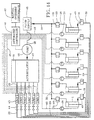
- pressurization of the control-cylinder units 1 can be partly hydraulic and partly pneumatic by employing pressurized gas to apply pressure to liquid with a pressure converter 54 such as a dual-fluid pressure tank as diagramed in FIG. 16.
- a pressure converter 54 such as a dual-fluid pressure tank as diagramed in FIG. 16.
- a preferred dual-fluid means of supply of pressurized control fluid to the control-cylinder units 1 has a comprehensive working relationship of pneumatic and hydraulic components with pluralities of backup duplicity and safety features that can be included within the FIG. 16 diagram.
- a preferred plurality of six control-cylinder units 1 have liquid conveyances 55 in fluid communication intermediate a duplicity of pressure-conversion vessels 56 and the control-cylinder units 1 .
- Level indicators 57 communicate pressure and volume factors for determining rate of gas pressurization through gas conveyances 59 from air-pressure groups 60 having pluralities of group pressure vessels 61 that are preferably five 22-inch-diameter pressure vessels.
- Gas pressure which is air pressure in this instance, is provided to the group pressure vessels 61 by a compressor unit 62 with which air is pressurized and stored in a plurality of backup-pressure vessels 63 that are preferably twelve 24-inch-diameter pressure vessels.
- the plurality of backup-pressure vessels 63 provide central storage of high volumes of compressed air for rapid availability for pressurizing a plurality of air-pressure groups 60 of group pressure vessels 61 for pressurizing a plurality of accumulator banks 70 of pressure-conversion vessels 56 to meet tensioning demands of a plurality of control-cylinder units 1 .
- Rate of flow of liquid under pressure through liquid conveyances 55 is regulated with a preferably six-inch large valve 64 and a preferably two-inch small valve 65 in each liquid conveyance 55.
- the tensioner valve panel 58 through which flow through the large valve 64 and the small valve 65 are regulated is represented broadly by the automated controller 41 and the manual-override controller 42 described in relation to FIGS. 14-16.
- Low-pressure air is conveyed intermediate low-pressure ends 66 of the control-cylinder units 1 and the tensioner valve panel 58 through return gas lines 67. Any liquid mixed with air is removed en route to control components at the tensioner valve panel 58.
- High-pressure air is conveyed through high-pressure lines 68 from the compressor unit 62 and the backup pressure vessels 63 en route to the gas conveyances 59 . Then it is routed to the pressure-conversion vessels 56 and the group pressure vessels 61 . Safety outlets 69 with appropriate valves and lines are provided for the group pressure vessels 61 and the backup pressure vessels 63.
- the pressure-conversion vessels 56 are proximate accumulator banks 70 where gas pressure is directed against liquid which is routed to pressurized portions of the control-cylinder units 1.
- Hydraulic and pneumatic symbols known to those skilled in the pertinent an are shown to indicate related design features such as select valves, pressure indicators conveyances and joints. Additional detail of the automated controller 41 and the manual-override controller 42 , however, are not explained in this document.
Landscapes
- Engineering & Computer Science (AREA)
- Geology (AREA)
- Mechanical Engineering (AREA)
- Life Sciences & Earth Sciences (AREA)
- Mining & Mineral Resources (AREA)
- General Life Sciences & Earth Sciences (AREA)
- Fluid Mechanics (AREA)
- Environmental & Geological Engineering (AREA)
- Physics & Mathematics (AREA)
- Geochemistry & Mineralogy (AREA)
- Chemical & Material Sciences (AREA)
- Combustion & Propulsion (AREA)
- Ocean & Marine Engineering (AREA)
- Earth Drilling (AREA)
- Fluid-Pressure Circuits (AREA)
Claims (30)
- Spannvorrichtung für eine Steigleitung, mit kontrolliertem Druck und mehreren Zylindern, umfassend:wobei die Anzahl von Steuerzylindereinheiten (1) distale Enden (5) aufweisen, die schwenkbar an einem Steigleitungs-Spannring (6) befestigt sind, wobei der Steigleitungs-Spannring (6) an dem proximalen Ende einer marinen Steigleitung (7) befestigt werden kann, die ein distales Ende aufweist, welches an einem Meeresboden (8) befestigt ist;eine Anzahl von Steuerzylindereinheiten (1) mit proximalen Enden (2), die schwenkbar an einem Seeschiff (4) in der Nähe eines Bodens einer Arbeitsebene (3) auf dem Seeschiff (4) befestigt sind;
Fluiddruckleitungen (20, 38) in Strömungsverbindung zwischen druckbeaufschlagten Abschnitten der Steuerzylindereinheiten (1) und steuerbaren Zuführungsmitteln (43, 44, 46, 52, 62, 64, 65) von druckbeaufschlagtem Steuerfluid zu den druckbeaufschlagten Abschnitten der Steuerzylinder (18, 25, 26, 32, 34, 37);
dadurch gekennzeichnet, daß die Spannvorrichtung für Steigleitungen weiterhin Druckaufnehmer (39) in druckanzeigender Kommunikation zwischen druckbeaufschlagten Abschnitten der Steuerzylindereinheiten (1) und den steuerbaren Zuführungsmitteln (43, 44, 46, 52, 62, 64, 65) für druckbeaufschlagtes Steuerfluid zu den druckbeaufschlagten Abschnitten der Steuerzylindereinheiten (1) aufweist;
wobei die steuerbaren Zuführungsmittel (43, 44, 46, 52, 62, 64, 65) für druckbeaufschlagtes Steuerfluid separat steuerbar sind, um druckbeaufschlagtes Steuerfluid für eine sich verändernde Abgabe von Spannkräften von separaten Stuerzylindereinheiten (1) bei Drücken und Volumenmengen zuzuführen, die eine vertikal nach oben gerichtete Spannung von Steuerzylindereinheiten (1) in selektiver Weise in kontrollierter Reaktion auf wellenerzeugte Positionierung, wettererzeugte Positionierung und in anderer Weise erzeugte Positionierung des Seeschiffs (4) in bezug auf einen Längenabschnitt der marinen Steigleitung (7) erzielen. - Spannvorrichtung für eine Steigleitung, mit kontrolliertem Druck und mehreren Zylindern, nach Anspruch 1, dadurch gekennzeichnet, daß die Druckaufnehmer (39) in druckerfassender Kommunikation mit innenliegenden Umfangsflächen der Flüiddruckleitungen (20, 38) angeordnet sind, zur druckanzeigenden Kommunkation zwischen Fluiddruck, der in den druckbeaufschlagten Abschnitten der Steuerzylindereinheiten (1) und den separat steuerbaren Zuführungsmitteln (43, 44, 46, 52, 62, 64, 65) von druckbeaufschlagtem Steuerfluid zu den druckbeaufschlagten Abschnitten der Steuerzylindereinheiten (1) herrscht.
- Spannvorrichtung für eine Steigleitung, mit kontrolliertem Druck und mehreren Zylindern, nach Anspruch 1, dadurch gekennzeichnet, daß die Druckaufnehmer (39) in druckerfassender Kommunikation mit innenliegenden Umfangsflächen der druckbeaufschlagten Abschnitte der Steuerzylindereinheiten (1) angeordnet sind, unmittelbar zur direkten druckanzeigenden Kommunikation zwischen Fluiddruck, der in den druckbeaufschlagten Abschnitten der Steuerzylindereinheiten (1) und den separat steuerbaren Zuführungsmitteln (43, 44, 46, 52, 62, 64, 65) von druckbeaufschlagtem Steuerfluid zu den druckbeaufschlagten Abschnitten der Steuerzylindereinheiten (1) herrscht.
- Spannvorrichtung für eine Steigleitung, mit kontrolliertem Druck und mehreren Zylindern, nach Anspruch 1, dadurch gekennzeichnet, daß die separat steuerbaren Zuführungsmittel (43, 44, 46, 52, 62, 64, 65) von druckbeaufschlagtem Fluid automatisch steuerbar sind mit automatisierten Steuerungen (41), die vorbestimmte automatisierte Antworten auf druckanzeigende Kommunikationen von den Druckübertragern (39) aufweisen.
- Spannvorrichtung für eine Steigleitung, mit kontrolliertem Druck und mehreren Zylindern, nach Anspruch 1, dadurch gekennzeichnet, daß die separat steuerbaren Zuführungsmittel (43, 44, 46, 52, 62, 64, 65) von druckbeaufschlagtem Fluid von Hand steuerbar sind mit zumindest einer Steuerung (42) mit manueller Übersteuerung, die vorbestimmte Steuerungsantworten auf druckanzeigende Kommunikationen von den Druckübertragern (39) bereitstellt.
- Spannvorrichtung für eine Steigleitung, mit kontrolliertem Druck und mehreren Zylindern, nach Anspruch 1, weiter gekennzeichnet durch:wobei die an einem proximalen Ende angeordneten Fluiddruckleitungen (20) in Strömungsverbindung mit den an einem distalen Ende angeordneten Fluiddruckleitungen (38) durch separat steuerbare Zuführungsmittel (43, 44, 46, 52, 62, 64, 65) von druckbeaufschlagtem Steuerfluid stehen; undan einem proximalen Ende angeordnete Fluiddruckleitungen (20) in Strömungsverbindung zwischen proximalen Enden von Steuerzylindereinheiten (1) und separat steuerbaren Zuführungsmitteln (43, 44, 46, 52, 62, 64, 65) von druckbeaufschlagtem Steuerfluid zu den proximalen Enden der Steuerzylindereinheiten (1);an einem distalen Ende angeordnete Fluiddruckleitungen (38) in Strömungsverbindung zwischen distalen Enden von Steuerzylindereinheiten (1) und separat steuerbaren Zuführungsmitteln (43, 44, 46, 52, 62, 64, 65) von druckbeaufschlagtem Steuerfluid zu den distalen enden der Steuerzylindereinheiten (1);
die separat steuerbaren Zuführungsmittel (43, 44, 46, 52, 62, 64, 65) von druckbeaufschlagtem Fluid automatisch zur Druckbeaufschlagung von distalen Enden und proximalen Enden der Steuerzylindereinheiten (1) steuerbar sind. - Spannvorrichtung für eine Steigleitung, mit kontrolliertem Druck und mehreren Zylindern, dadurch gekennzeichnet, daß:wobei die Steuerzylinder (18) jeweils einen Kolben (21) in verschieblichem und dichtendem Kontakt mit einer inneren Umfangsfläche eines jeden der Steuerzylinder (18) aufweisen, so daß eine Anzahl von Kolben (21), die gleich der Anzahl von Steuerzylindern (18) ist, sich in verschieblichem und dichtendem Kontakt mit inneren Umfangsflächen der Steuerzylinder (18) befindet;die Steuerzylindereinheiten (1) Steuerzylinder (18) mit als Zylinderabschlüsse ausgeführten proximalen Enden (2) aufweisen, die schwenkbar an einem Seeschiff (4) in der Nähe eines Bodens einer Arbeitsebene (3) auf dem Seeschiff (2) befestigt sind;
wobei proximale Enden von Kolbenstangen (17) an Kolbenstangenseiten der Kolben (21) befestigt sind;
wobei die Kolbenstangen (17) distale Enden aufweisen, die schwenkbar an dem Steigleitungs-Spannring (6) befestigt sind;
wobei die Steuerzylinder (18) kolbenstangenseitig Zylinderköpfe aufweisen, mit denen die Kolbenstangen (17) in verschieblichem und dichtendem Kontakt stehen;
wobei die Fluiddruckleitungen (20) in Strömungsverbindung zwischen den distalen Enden der Steuerzylinder (18) und den separat steuerbaren Zuführungsmitteln (43, 44, 46, 52, 62, 64, 65) von druckbeaufschlagtem Steuerfluid zu den distalen Enden der Steuerzylinder (18) stehen; und
wobei die Druckübertrager (29) in druckanzeigender Kommunikation zwischen Fluiddrücken stehen, die in den distalen Enden der Steuerzylinder (18) und den separat steuerbaren Zuführungsmitteln (43, 44, 46, 52, 62, 64, 65) von druckbeaufschlagtem Steuerfluid zu den distalen Enden der Steuerzylinder (18) herrschen. - Spannvorrichtung für eine Steigleitung, mit kontrolliertem Druck und mehreren Zylindern, nach Anspruch 7, weiter gekennzeichnet durch:Fluiddruckleitungen (20) in Strömungsverbindung zwischen den proximalen Enden der Steuerzylinder (18) und separat steuerbaren Zuführungsmitteln (43, 44, 46, 52, 62, 64, 65) von druckbeaufschlagtem Steuerfluid zu den proximalen Enden der Steuerzylinder (18);Druckübertrager (39) in druckanzeigender Kommunikation zwischen Fluiddrücken, die in den proximalen Enden der Steuerzylinder (18) und in den separat steuerbaren Zuführungsmitteln (43, 44, 46, 52, 62, 64, 65) von druckbeaufschlagtem Steuerfluid zu den proximalen Enden der Steuerzylinder (18) herrschen; wobei die separat steuerbaren Zuführungsmittel (43, 44, 46, 52, 62, 64, 65) von druckbeaufschlagtem Fluid so steuerbar sind, daß sie druckbeaufschlagtes Steuerfluid mit selektiv konstanten Drücken an proximale Enden der Steuerzylinder (43, 44, 46, 52, 62, 64, 65) zuführen.
- Spannvorrichtung für eine Steigleitung, mit kontrolliertem Druck und mehreren Zylindern, nach Anspruch 1, dadurch gekennzeichnet, daß:wobei die Steuerzylinder (26) jeweils einen Kolben (33) in verschieblichem und dichtendem Kontakt mit einer innenliegenden Umfangsfläche eines jeden der Steuerzylinder (26) aufweisen, so daß eine Anzahl von Kolben (33), die gleich der Anzahl von Steuerzylindern (36) ist, in verschieblichem und dichtendem Kontakt mit inneren Umfangsflächen der Steuerzylinder (26) stehen;die Steuerzylindereinheiten (1) Steuerzylinder (26) mit als Zylinderabschlüsse ausgeführten proximalen Enden (5) aufweisen, die schwenkbar an einem Steigleitungs-Spannring (6) befestigt sind;
wobei proximale Enden von Kolbenstangen (30) an Kolbenstangenseiten der Kolben (33) befestigt sind;
wobei die Kolbenstangen (30) distale Enden aufweisen, die schwenkbar an einem Seeschiff (4) in der Nähe eines Bodens einer Arbeitsebene (3) auf dem Seeschiff (4) befestigt sind;
wobei die Steuerzylinder (26) kolbenstangenendseitig Zylinderköpfe aufweisen, mit denen die Kolbenstangen (30) in verschieblichem und dichtendem Kontakt benachbart zu distalen Enden der Steuerzylinder (26) stehen;
wobei die Fluiddruckleitungen (38) in Strömungsverbindung zwischen den distalen Enden der Steuerzylinder (26) und den separat steuerbaren Zuführungsmitteln (43, 44, 46, 52, 62, 64, 65) von druckbeaufschlagtem Steuerfluid zu den distalen Enden der Steuerzylinder (26) stehen;
wobei die Druckübertrager (39) in druckanzeigender Kommunikation zwischen Fluiddrücken stehen, die in den distalen Enden der Steuerzylinder (26) und den separat steuerbaren Zuführungsmitteln (43, 44, 46, 52, 62, 64, 65) von druckbeaufschlagtem Steuerfluid zu den distalen Enden der Steuerzylinder (26) herrschen; und
die separat steuerbaren Zuführungsmittel (43, 44, 46, 52, 62, 64, 65) von druckbeaufschlagtem Fluid so steuerbar sind, daß sie druckbeaufschlagtes Fluid mit selektiv konstanten Drücken an distale Enden von Steuerzylindern (26) abgeben. - Spannvorrichtung für eine Steigleitung, mit kontrolliertem Druck und mehreren Zylindern, nach Anspruch 1, dadurch gekennzeichnet, daß:wobei die ersten, als Zylinderabschlüsse ausgeführten Enden auf den ersten Steuerzylindern (25) schwenkbar an einem Seeschiff (4) in der Nähe eines Bodens einer Arbeitsebene (3) auf dem Seeschiff (4) befestigt sind;die Steuerzylindereinheiten (1) endseitig aneinander und linear einander entgegengerichtet angeordnete Paare von Steuerzylindern (25, 26) sind, die erste Steuerzylinder (25) aufweisen, auf denen sich erste, als Zylinderabschlüsse ausgeführte Enden befinden, und zweite Steuerzylinder (26), auf denen sich zweite, als Zylinderabschlüsse ausgeführte Enden befinden;
wobei die zweiten, als Zylinderabschlüsse ausgeführten Enden auf den zweiten Steuerzylindern (26) schwenkbar an einem Steigleitungs-Spannring (6) befestigt sind;
wobei die ersten Steuerzylinder (25) distale Enden von ersten Zylindern aufweisen, mit kolbenstangenseitigen Köpfen, durch die obere Kolbenstangen (27) in verschieblichem und dichtendem Kontakt geführt sind;
wobei die zweiten Steuerzylinder (26) distale Enden von zweiten Zylindern aufweisen, mit kolbenstangenseitigen Köpfen, durch die untere Kolbenstangen (27) in verschieblichem und dichtendem Kontakt geführt sind;
wobei die oberen Kolbenstangen (27) an ersten Kolben (28) befestigt sind, die sich in verschieblichem und dichtendem Kontakt mit einer inneren Umfangsfläche der ersten Steuerzylinder (25) befinden;
wobei die unteren Kolbenstangen (27) an zweiten Kolben (29) befestigt sind, die sich in verschieblichem und dichtendem Kontakt mit einer inneren Umfangsfläche der zweiten Steuerzylinder (26) befinden; und
die oberen Kolbenstangen (27) und die unteren Kolbenstangen (27) Befestigungsenden aufweisen, mit denen die oberen Kolbenstangen (27) und die unteren Kolbenstangen (27) endseitig und linear aneinander befestigt sind. - Spannvorrichtung für eine Steigleitung, mit kontrolliertem Druck und mehreren Zylindern, nach Anspruch 1, dadurch gekennzeichnet, daß:die Steuerzylindereinheiten (1) endseitig aneinander und linear einander entgegengerichtet angeordnete Paare von Steuerzylindern (32, 34) sind, die erste Steuerzyinder (32) aufweisen, an denen sich erste, als Zylinderabschlüsse ausgeführte Enden befinden, und zweite Steuerzylinder (34), auf denen sich zweite, als Zylinderabschlüsse ausgeführte Enden befinden;die ersten, als Zylinderabschlüsse ausgeführten Enden auf den ersten Steuerzylindern (32) endseitig aneinander und linear an den zweiten, als Zylinderabschlüsse ausgeführten Enden (34) auf den zweiten Steuerzylindern befestigt sind;die ersten Steuerzylinder (32) distale Enden von ersten Zylindern aufweisen, mit kolbenstangenseitigen Köpfen, durch die obere Kolbenstangen (30) in veschieblichem und gleitendem Kontakt geführt sind;die zweiten Steuerzylinder (34) distale Enden von zweiten Zylindern aufweisen, mit kolbenstangenseitigen Köpfen, durch die untere Kolbenstangen (31) in verschieblichem und dichtendem Kontakt geführt sind;die oberen Kolbenstangen (30) an ersten Kolben (33) befestigt sind, die sich in verschieblichem und dichtendem Kontakt mit einer inneren Umfangsfläche der ersten Steuerzylinder (32) befinden;die unteren Kolbenstangen (31) an zweiten Kolben (35) befestigt sind, die sich in verschieblichem und dichtendem Kontakt mit einer inneren Umfangsfläche der zweiten Steuerzylinder (34) befinden; unddie oberen Kolbenstangen (30) und die unteren Kolbenstangen (31) Befestigungsenden aufweisen, mit denen die oberen Kolbenstangen (30) schwenkbar an einem Seeschiff (4) in der Nähe eines Bodens einer Arbeitsebene (4) auf dem Seeschiff (3) befestigt sind, und die unteren Kolbenstangen (31) an dem Steigleitungs-Spannring (6) befestigt sind.
- Spannvorrichtung für eine Steigleitung, mit kontrolliertem Druck und mehreren Zylindern, nach Anspruch 1, dadurch gekennzeichnet, daß:der Steigleitungs-Spannring (6) von geteilter Bauart ist, mit einem ersten halbzylinderförmigen Abschnitt (22) einer Befestigungsöffnung für eine Steigleitung in einer ersten Seite und mit einem zweiten halbzylinderförmigen Abschnitt (23) der Befestigungsöffnung für die Steigleitung in einer zweiten Seite des Steigleitungs-Spannrings (6).
- Spannvorrichtung für eine Steigleitung, mit kontrolliertem Druck und mehreren Zylindern, nach Anspruch 1, dadurch gekennzeichnet, daß die schwenkbare Befestigung der Steuerzylindereinheiten (1) an dem Seeschiff durch Verbindungen mit Kugel und Sockel (19) ausgeführt ist.
- Spannvorrichtung für eine Steigleitung, mit kontrolliertem Druck und mehreren Zylindem, nach Anspruch 1, dadurch gekennzeichnet, daß die schwenkbare Befestigung der Steuerzylindereinheiten (1) an dem Steigleitungs-Spannring (6) mittels Verbindungen mit Kugel und Sockel (19) ausgeführt ist.
- Spannvorrichtung für eine Steigleitung, mit kontrolliertem Druck und mehreren Zylindern, nach Anspruch 1, dadurch gekennzeichnet, daß die separat steuerbaren Zuführungsmittel (43, 44, 46, 62, 64, 65) von druckbeaufschlagtem Steuerfluid separat gesteuerte Ventileinheiten (43, 64, 65) in zentral gesteuerter Strömungsverbindung zwischen einer zentralen Pumpe (46, 62) und den Steuerzylindereinheiten (1) aufweist; und daß die zentrale Pumpe (64, 62) in Strömungsverbindung von einer Fluidzuführungsquelle (48, 63) angeordnet ist.
- Spannvorrichtung für eine Steigleitung, mit kontrolliertem Druck und mehreren Zylindern, nach Anspruch 15, weiter gekennzeichnet durch einen zentralen Speicher (47) in Strömungsverbindung zwischen der zentralen Pumpe (46) und den zentral gesteuerten Ventileinheiten (43).
- Spannvorrichtung für eine Steigleitung, mit kontrolliertem Druck und mehreren Zylindern, nach Anspruch 1, dadurch gekennzeichnet, daß die separat steuerbaren Zuführungsmittel (43, 44, 52) von druckbeaufschlagtem Steuerfluid separat gesteuerte Pumpen (52) und Ventileinheiten (43) aufweisen, die in zentral gesteuerter Strömungsverbindung zwischen einer Fluidzuführungsquelle (48) und den Steuerzylindereinheiten (1) angeordnet sind.
- Spannvorrichtung für eine Steigleitung, mit kontrolliertem Druck und mehreren Zylindem, nach Anspruch 17, weiter gekennzeichnet durch getrennte Speicher (53) in Strömungsverbindung zwischen den separat gesteuerten Pumpen (52) und Ventileinheiten (43).
- Spannvorrichtung für eine Steigleitung, mit kontrolliertem Druck und mehreren Zylindern, nach Anspruch 1, dadurch gekennzeichnet, daß die separat steuerbaren Zuführungsmittel (43, 44, 46, 52, 62, 64, 65) von druckbeaufschlagtem Steuerfluid an die druckbeaufschlagten Abschnitte der Steuerzylinder (1) eine Flüssigkeitspumpe (46) in Strömungsverbindung von einer Fluidzuführungsquelle (48) zu den Fluiddruckleitungen (20) aufweisen.
- Spannvorrichtung für eine Steigleitung, mit kontrolliertem Druck und mehreren Zylindern, nach Anspruch 1, dadurch gekennzeichnet, daß die separat steuerbaren Zuführungsmittel (62, 64, 65) von druckbeaufschlagtem Steuerfluid an die druckbeaufschlagten Abschnitte der Steuerzylinder (1) einen Luftkompressor (62) in Strömungsverbindung mit den Fluiddruckleitungen (20) aufweisen.
- Spannvorrichtung für eine Steigleitung, mit kontrolliertem Druck und mehreren Zylindem, nach Anspruch 1, dadurch gekennzeichnet, daß die separat steuerbaren Zuführungsmittel (43, 44, 46, 52, 62, 64, 65) von druckbeaufschlagtem Steuerfluid an die druckbeaufschlagten Abschnitte der Steuerzylinder (1) einen Luftkompressor (46, 62) in Strömungsverbindung mit einem Druckumwandler (54, 56) aufweisen, in dem Druckluft gegen Flüssigkeit geleitet wird, die zu den Fluiddruckleitungen (25) geleitet wird.
- Spannvorrichtung für eine Steigleitung, mit kontrolliertem Druck und mehreren Zylindern, nach Anspruch 21, weiter gekennzeichnet durch:eine Anzahl von Druckreservekesseln (63), in die Druckluft von dem Luftkompressor (62) geleitet wird, zur zentralen Speicherung großer Volumenmengen von Druckluft zur schnellen Verfügbarkeit zum Druckbeaufschlagen einer Anzahl von Steuerzylindereinheiten (1);eine Anzahl von Luftdruckgruppen von Gruppendruckkesseln (61), in die Druckluft von dem Luftkompressor (62) und/oder den Druckreservekesseln (63) geleitet wird;eine Anzahl von Speicherblöcken (70) von Druckumwandlungskesseln (56), in denen Druckluft von Gruppendruckkesseln (61) gegen eine Flüssigkeit geleitet wird, die separat zu der Anzahl von Steuerzylindereinheiten (1) geleitet wird; undeine Anzahl von Flüssigkeitsübertragungen (55) in Strömungsverbindung von den Druckumwandlungskesseln (56) zu den druckbeaufschlagten Abschnitten der Steuerzylinder (1).
- Spannvorrichtung für eine Steigleitung, mit kontrolliertem Druck und mehreren Zylindern, nach Anspruch 22, und weiter gekennzeichnet durch: eine Anzahl von großen Ventilen (64) in der Anzahl von Flüssigkeitsübertragungen (55); wobei die Anzahl von großen Ventilen (64) eine selektive Strömungssteuerung durch die Flüssigkeitsübertragungen (55) aufweist.
- Spannvorrichtung für eine Steigleitung, mit kontrolliertem Druck und mehreren Zylindern, nach Anspruch 23, und weiter gekennzeichnet durch eine Anzahl von kleinen Ventilen (65) in der Anzahl von Flüssigkeitsübertragungen (55); wobei die Anzahl von kleinen Ventilen (65) eine wahlweise selektive Strömungssteuerung durch die Flüssigkeitsübertragungen (55) aufweist.
- Spannvorrichtung für eine Steigleitung, mit kontrolliertem Druck und mehreren Zylindern, nach Anspruch 24, weiter gekennzeichnet durch eine Anzahl von Gasrücklaufleitungen (67) in Strömungsverbindung von Niederdruckenden der Steuerzylindereinheiten (1) zu einer Anzahl von Spannventiltafeln (58).
- Verfahren mit den folgenden Schritten zum Spannen einer marinen Steigleitung:dadurch gekennzeichnet, daß die Steuerzylindereinheiten (1) separat steuerbare Spannkräfte aufweisen, und daß Steuerfluid separat mit solchen Zuführungsraten und Druckhöhen an die Steuerzylindereinheiten (1) zugeführt wird, um druckbeaufschlagtes Steuerfluid an variable Zylindervolumengrößen von separaten Steuerzylindereinheiten (1) bei Drücken und Volumenmengen bereitzustellen, um vertikal nach oben gerichtete Drücke der Steuerzylinder (18, 25, 26, 32, 34, 37) selektiv zu erzielen, als kontrollierte Reaktion auf wellenerzeugte Positionierung, wettererzeugte Positionierung und in anderer Weise erzeugte Positionierung des Seeschiffs (4) in bezug auf einen Längenabschnitt der gespannten marinen Steigleitung (7).Bereitstellen einer Anzahl von Steuerzylindereinheiten (1), die eine steuerbare Spannkraft in einer nach oben weisenden Spannrichtung aufweisen;schwenkbares Befestigen von oberen Enden der Steuerzylindereinheiten (1) an einem Seeschiff (4) um einen unteren Teil eines Bohrschaft-Einfügungsabschnitts einer Arbeitsebene (3) des Seeschiffs (4);schwenkbares Befestigen von unteren Enden der Steuerzylindereinheiten (1) an einem Steigleitungs-Spannring (6) vertikal unterhalb der Arbeitsebene (3);Befestigen eines proximalen Endes einer zu spannenden marinen Steigleitung (7) an dem Steigleitungs-Spannring (6) und Befestigen und Verankern eines distalen Endes der zu spannenden marinen Steigleitung an einem Meeresboden (8);
- Verfahren nach Anspruch 26, dadurch gekennzeichnet, daß eine Zuführung von Steuerfluid an die Steuerzylindereinheiten (1) in separater Weise bereitgestellt wird, mit separaten Zuführungsquellen (43, 44, 46, 52, 62, 64, 65), die separate Steuereinheiten (43, 44, 52, 64, 65) in steuerbarer Kommunikation mit geschlossener Schleife mit den Steuerzylindereinheiten (1) aufweisen.
- Verfahren nach Anspruch 26, dadurch gekennzeichnet, daß das Steuerfluid, das den Steuerzylindereinheiten (I) zugeführt wird, eine Flüssigkeit ist, die mittels einer Flüssigkeitspumpe (46, 52) gepumpt wird.
- Verfahren nach Anspruch 26, dadurch gekennzeichnet, daß das Steuerfluid, das den Steuerzylindereinheiten (1) zugeführt wird, Luft ist, die mittels eines Luftkompressors (62) gepumpt wird.
- Verfahren nach Anspruch 26, dadurch gekennzeichnet, daß das Steuerfluid, das an die steuerzylinder (1) zugeführt wird, eine Flüssigkeit ist, die durch Druckluft, die mittels eines Luftkompressors (46) gepumpt wird, mit Druck beaufschlagt wird.
Applications Claiming Priority (2)
| Application Number | Priority Date | Filing Date | Title |
|---|---|---|---|
| US08/904,672 US5846028A (en) | 1997-08-01 | 1997-08-01 | Controlled pressure multi-cylinder riser tensioner and method |
| US904672 | 1997-08-01 |
Publications (3)
| Publication Number | Publication Date |
|---|---|
| EP0894939A2 EP0894939A2 (de) | 1999-02-03 |
| EP0894939A3 EP0894939A3 (de) | 1999-07-07 |
| EP0894939B1 true EP0894939B1 (de) | 2003-11-12 |
Family
ID=25419548
Family Applications (1)
| Application Number | Title | Priority Date | Filing Date |
|---|---|---|---|
| EP98202608A Expired - Lifetime EP0894939B1 (de) | 1997-08-01 | 1998-08-03 | Unterwasser-Steigleitung mit mehrfach Spannzylinder mit kontrollierbarem Druck und dazugehöriges Verfahren |
Country Status (4)
| Country | Link |
|---|---|
| US (1) | US5846028A (de) |
| EP (1) | EP0894939B1 (de) |
| DE (1) | DE69819619T2 (de) |
| NO (1) | NO318185B1 (de) |
Cited By (1)
| Publication number | Priority date | Publication date | Assignee | Title |
|---|---|---|---|---|
| CN102330541A (zh) * | 2011-08-05 | 2012-01-25 | 宝鸡石油机械有限责任公司 | 海洋钻井隔水管张紧系统 |
Families Citing this family (75)
| Publication number | Priority date | Publication date | Assignee | Title |
|---|---|---|---|---|
| US6017168A (en) * | 1997-12-22 | 2000-01-25 | Abb Vetco Gray Inc. | Fluid assist bearing for telescopic joint of a RISER system |
| US6561735B1 (en) * | 1998-07-06 | 2003-05-13 | Seahorse Equipment Corporation | Well riser lateral restraint and installation system for offshore platform |
| NO311374B1 (no) * | 1998-09-25 | 2001-11-19 | Eng & Drilling Machinery As | Fremgangsmate ved holding av stigeror under strekk og anordning for a sette stigeror under strekk |
| US6691784B1 (en) * | 1999-08-31 | 2004-02-17 | Kvaerner Oil & Gas A.S. | Riser tensioning system |
| US6547491B1 (en) * | 2000-03-17 | 2003-04-15 | J. Ray Mcdermott, S.A. | Hydrostatic equalization for an offshore structure |
| BR0110377A (pt) * | 2000-04-27 | 2004-02-10 | Cooper Cameron Corp | Sistema e método para o controle de rebobinação de elevador |
| US6554072B1 (en) | 2000-06-15 | 2003-04-29 | Control Flow Inc. | Co-linear tensioner and methods for assembling production and drilling risers using same |
| ATE321934T1 (de) | 2000-06-15 | 2006-04-15 | Control Flow Inc | Teleskopische spannvorrichtung für eine steigrohrverbindung |
| US6425710B1 (en) * | 2000-06-21 | 2002-07-30 | Jon Khachaturian | Articulated multiple buoy marine platform apparatus |
| US6719495B2 (en) | 2000-06-21 | 2004-04-13 | Jon E. Khachaturian | Articulated multiple buoy marine platform apparatus and method of installation |
| US6648074B2 (en) * | 2000-10-03 | 2003-11-18 | Coflexip S.A. | Gimbaled table riser support system |
| AU2001288897B2 (en) * | 2000-10-20 | 2006-11-16 | Jon E. Khachaturian | Articulated multiple buoy marine platform apparatus and method of installing same |
| US6422316B1 (en) * | 2000-12-08 | 2002-07-23 | Rti Energy Systems, Inc. | Mounting system for offshore structural members subjected to dynamic loadings |
| NO20012079L (no) * | 2001-04-27 | 2002-10-28 | Nat Oilwell Norway As | Frakoplebar stigerörstrekkböye |
| US6609572B1 (en) * | 2002-02-01 | 2003-08-26 | Smedvig Offshore As | Riser connector |
| US7104329B2 (en) * | 2002-04-26 | 2006-09-12 | Bp Corporation North America Inc. | Marine bottomed tensioned riser and method |
| GB0213996D0 (en) * | 2002-06-18 | 2002-07-31 | Wood Robert A | Gas spring and air cylinder for lifting a variable height roller assembly |
| US6869254B1 (en) | 2002-10-23 | 2005-03-22 | Electrowaveusa | Riser tensioner sensor assembly |
| NO317230B1 (no) * | 2002-11-12 | 2004-09-20 | Nat Oilwell Norway As | Todelt teleskopisk strammer for stigeror ved en flytende installasjon for olje- og gassproduksjon |
| US20040099421A1 (en) * | 2002-11-27 | 2004-05-27 | Expro Americas, Inc. | Motion compensation system for watercraft connected to subsea conduit |
| US6968900B2 (en) * | 2002-12-09 | 2005-11-29 | Control Flow Inc. | Portable drill string compensator |
| US7008340B2 (en) * | 2002-12-09 | 2006-03-07 | Control Flow Inc. | Ram-type tensioner assembly having integral hydraulic fluid accumulator |
| US7231981B2 (en) * | 2003-10-08 | 2007-06-19 | National Oilwell, L.P. | Inline compensator for a floating drill rig |
| US20050074296A1 (en) * | 2003-10-15 | 2005-04-07 | Mccarty Jeffery Kirk | Hydro-pneumatic tensioner with stiffness altering secondary accumulator |
| US6929071B2 (en) * | 2003-12-15 | 2005-08-16 | Devin International, Inc. | Motion compensation system and method |
| US20050147473A1 (en) * | 2004-01-07 | 2005-07-07 | Vetco Gray Inc. | Riser tensioner with shrouded rods |
| US20060280560A1 (en) * | 2004-01-07 | 2006-12-14 | Vetco Gray Inc. | Riser tensioner with shrouded rods |
| US7293939B2 (en) * | 2004-02-10 | 2007-11-13 | Phillip Andrew Abbott | Inclined leg floating production platform with a damper plate |
| NO322172B1 (no) * | 2004-05-21 | 2006-08-21 | Fmc Kongsberg Subsea As | Anordning i forbindelse med hivkompensering av et trykksatt stigeror forlopende mellom en havbunnsinstallasjon og en flytende enhet. |
| US7191837B2 (en) * | 2004-07-20 | 2007-03-20 | Coles Robert A | Motion compensator |
| US7191836B2 (en) * | 2004-08-02 | 2007-03-20 | Kellogg Brown & Root Llc | Dry tree subsea well communications apparatus and method using variable tension large offset risers |
| NO320518B1 (no) * | 2004-09-13 | 2005-12-12 | Power Vision As | Bolgekraftverk |
| US7823646B2 (en) * | 2004-11-19 | 2010-11-02 | Vetco Gray Inc. | Riser tensioner with lubricant reservoir |
| US7926593B2 (en) | 2004-11-23 | 2011-04-19 | Weatherford/Lamb, Inc. | Rotating control device docking station |
| US20060180314A1 (en) * | 2005-02-17 | 2006-08-17 | Control Flow Inc. | Co-linear tensioner and methods of installing and removing same |
| US7314087B2 (en) * | 2005-03-07 | 2008-01-01 | Halliburton Energy Services, Inc. | Heave compensation system for hydraulic workover |
| US7219739B2 (en) * | 2005-03-07 | 2007-05-22 | Halliburton Energy Services, Inc. | Heave compensation system for hydraulic workover |
| US8141644B2 (en) * | 2005-09-14 | 2012-03-27 | Vetco Gray Inc. | System, method, and apparatus for a corrosion-resistant sleeve for riser tensioner cylinder rod |
| US7819195B2 (en) * | 2005-11-16 | 2010-10-26 | Vetco Gray Inc. | External high pressure fluid reservoir for riser tensioner cylinder assembly |
| NO329688B1 (no) * | 2006-06-01 | 2010-11-29 | Nat Oilwell Norway As | Anordning ved heisesystem |
| US20080187401A1 (en) * | 2007-02-02 | 2008-08-07 | Tom Bishop | Riser tensioner for an offshore platform |
| US7934561B2 (en) * | 2007-04-10 | 2011-05-03 | Intermoor, Inc. | Depth compensated subsea passive heave compensator |
| EP2650465A1 (de) * | 2008-04-10 | 2013-10-16 | Weatherford/Lamb Inc. | Landestrangkompensator |
| US8083440B2 (en) * | 2008-08-07 | 2011-12-27 | Diamond Offshore Drilling, Inc. | Riser tensioner restraint device |
| US20110011320A1 (en) * | 2009-07-15 | 2011-01-20 | My Technologies, L.L.C. | Riser technology |
| NO331342B1 (no) * | 2009-09-15 | 2011-12-05 | Nat Oilwell Norway As | Stigerors strekkanordning |
| US20110091284A1 (en) * | 2009-10-19 | 2011-04-21 | My Technologies, L.L.C. | Rigid Hull Gas-Can Buoys Variable Buoyancy |
| NO331541B1 (no) * | 2009-11-10 | 2012-01-23 | Future Production As | Sammenkoblingsinnretning for drepe/strupe-linjer mellom et stigeror og et flytende borefartoy |
| US20110209651A1 (en) * | 2010-03-01 | 2011-09-01 | My Technologies, L.L.C. | Riser for Coil Tubing/Wire Line Injection |
| WO2012032104A2 (en) * | 2010-09-09 | 2012-03-15 | Aker Mh As | A seafastening apparatus for a tensioner assembly |
| NO332505B1 (no) | 2010-12-03 | 2012-10-01 | Frigstad Engineering Ltd | Anordning for handtering av slanger ved en arbeidsbronn for en borerigg |
| US8157013B1 (en) * | 2010-12-08 | 2012-04-17 | Drilling Technological Innovations, LLC | Tensioner system with recoil controls |
| US8579034B2 (en) * | 2011-04-04 | 2013-11-12 | The Technologies Alliance, Inc. | Riser tensioner system |
| US8517110B2 (en) | 2011-05-17 | 2013-08-27 | Drilling Technology Innovations, LLC | Ram tensioner system |
| US8789604B2 (en) * | 2011-12-27 | 2014-07-29 | Vetco Gray Inc. | Standalone liquid level sensing apparatus for tensioner system |
| WO2013101899A1 (en) | 2011-12-30 | 2013-07-04 | National Oilwell Varco, L.P. | Deep water knuckle boom crane |
| NO339757B1 (no) | 2012-12-10 | 2017-01-30 | Mhwirth As | Strekkmaskiner for stigerør med multippel kapasitet |
| US8727018B1 (en) * | 2013-07-19 | 2014-05-20 | National Oilwell Varco, L.P. | Charging unit, system and method for activating a wellsite component |
| MY172059A (en) * | 2014-04-08 | 2019-11-13 | Mhd Offshore Group Sdn Bhd | Apparatus to adjust bi-directional hydraulic damping properties for offshore in-line passive heave compensators |
| AU2014221195B2 (en) | 2014-09-02 | 2016-07-21 | Icon Engineering Pty Ltd | Riser tension protector and method of use thereof |
| AU2014221196B2 (en) | 2014-09-02 | 2016-07-07 | Icon Engineering Pty Ltd | Coiled tubing lift frame assembly and method of use thereof |
| EP3144543A1 (de) * | 2015-09-17 | 2017-03-22 | Robert Bosch Gmbh | Vorrichtung und verfahren zur steuerung eines sichereitsventilaggregats |
| NO20160251A1 (no) * | 2016-02-12 | 2017-08-14 | Birkenes Haakon | Hold åpen ventil funksjon |
| US10174566B2 (en) | 2016-03-02 | 2019-01-08 | Vetco Gray, LLC | Inverted pull-up riser tensioner |
| CN105649560B (zh) * | 2016-03-31 | 2018-05-04 | 中国石油大学(华东) | 海洋浮式钻井隔水管柔性悬挂器 |
| GB2549096A (en) * | 2016-04-04 | 2017-10-11 | Maersk Drilling As | Riser retention system and drillship with the same |
| CN107366514B (zh) * | 2016-05-12 | 2019-10-18 | 辽宁陆海石油装备研究院有限公司 | 一种自升式钻井平台隔水管张紧器 |
| NO345743B1 (en) * | 2017-05-19 | 2021-07-12 | AME Pty Ltd | Compensated elevator link |
| US10550864B1 (en) | 2017-07-24 | 2020-02-04 | Innovative Hydraulics, LLC | Hydraulic cylinder arrangement with automatic air bleeding and fluid flushing features |
| CN107628198B (zh) * | 2017-09-04 | 2019-07-26 | 中国船舶工业集团公司第七0八研究所 | 一种自张紧式张力筋腱及其安装方法 |
| CN110513055B (zh) * | 2018-05-22 | 2021-01-15 | 中国石油大学(华东) | 一种混合式海洋隔水管张紧器装置 |
| KR102629058B1 (ko) * | 2018-10-01 | 2024-01-23 | 삼성중공업 주식회사 | 실린더 타입 라이저 텐셔너 |
| EP3653561A1 (de) * | 2018-11-13 | 2020-05-20 | NHLO Holding B.V. | (hub)ausgleichsvorrichtung, hubsystem, verfahren zum heben und teilesatz zum federausgleich eines hubsystems |
| US20250136253A1 (en) * | 2021-08-27 | 2025-05-01 | Eni S.P.A. | Mooring device and method |
| CN116519881B (zh) * | 2023-04-27 | 2025-10-31 | 燕山大学 | 液压气动式张紧器实验模拟装置 |
Family Cites Families (25)
| Publication number | Priority date | Publication date | Assignee | Title |
|---|---|---|---|---|
| US3601187A (en) * | 1969-05-02 | 1971-08-24 | Exxon Production Research Co | Drilling riser |
| GB1309933A (en) * | 1970-06-29 | 1973-03-14 | Shell Int Research | Floating structure provided with a dynamic stationing system |
| US3943868A (en) * | 1974-06-13 | 1976-03-16 | Global Marine Inc. | Heave compensation apparatus for a marine mining vessel |
| GB1526239A (en) * | 1975-12-30 | 1978-09-27 | Shell Int Research | Marine riser system and method for installing the same |
| GB1600740A (en) * | 1977-04-23 | 1981-10-21 | Brown Bros & Co Ltd | Tensioner device for offshore oil production and exploration platfroms |
| US4222341A (en) * | 1978-01-11 | 1980-09-16 | Western Gear Corporation | Riser tensioning wave and tide compensating system for a floating platform |
| US4364323A (en) * | 1980-01-26 | 1982-12-21 | Vickers Limited | Vertical stressed mooring tether in a floating oil platform |
| US4379657A (en) * | 1980-06-19 | 1983-04-12 | Conoco Inc. | Riser tensioner |
| GB2094856B (en) * | 1981-01-28 | 1984-12-19 | Southeastern Drilling Services | Slip assembly for subsea template |
| US4449854A (en) * | 1981-02-12 | 1984-05-22 | Nl Industries, Inc. | Motion compensator system |
| US4367981A (en) * | 1981-06-29 | 1983-01-11 | Combustion Engineering, Inc. | Fluid pressure-tensioned slip joint for drilling riser |
| US4423983A (en) * | 1981-08-14 | 1984-01-03 | Sedco-Hamilton Production Services | Marine riser system |
| US4501219A (en) * | 1983-04-04 | 1985-02-26 | Nl Industries, Inc. | Tensioner apparatus with emergency limit means |
| US4473323A (en) * | 1983-04-14 | 1984-09-25 | Exxon Production Research Co. | Buoyant arm for maintaining tension on a drilling riser |
| GB8328147D0 (en) * | 1983-10-21 | 1983-11-23 | Vickers Plc | Marine heave compensating device |
| US4576516A (en) * | 1984-11-28 | 1986-03-18 | Shell Oil Company | Riser angle control apparatus and method |
| DK304285D0 (da) * | 1985-07-03 | 1985-07-03 | Atlas Ingeniorforretningen | Lejekonstruktion og fartoej med en saadan lejekonstruktion |
| US4626136A (en) * | 1985-09-13 | 1986-12-02 | Exxon Production Research Co. | Pressure balanced buoyant tether for subsea use |
| US4657439A (en) * | 1985-12-18 | 1987-04-14 | Shell Offshore Inc. | Buoyant member riser tensioner method and apparatus |
| FR2593227B1 (fr) * | 1986-01-21 | 1988-04-29 | Framatome Sa | Procede et dispositif de connexion de lignes associees a un equipement de forage en mer comportant un joint telescopique |
| US4799827A (en) * | 1986-11-17 | 1989-01-24 | Vetco Gray Inc. | Modular riser tensioner incorporating integral hydraulic cylinder accumulator units |
| US4883387A (en) * | 1987-04-24 | 1989-11-28 | Conoco, Inc. | Apparatus for tensioning a riser |
| US4808035A (en) * | 1987-05-13 | 1989-02-28 | Exxon Production Research Company | Pneumatic riser tensioner |
| GB2250763B (en) * | 1990-12-13 | 1995-08-02 | Ltv Energy Prod Co | Riser tensioner system for use on offshore platforms using elastomeric pads or helical metal compression springs |
| US5551803A (en) * | 1994-10-05 | 1996-09-03 | Abb Vetco Gray, Inc. | Riser tensioning mechanism for floating platforms |
-
1997
- 1997-08-01 US US08/904,672 patent/US5846028A/en not_active Expired - Fee Related
-
1998
- 1998-07-31 NO NO19983534A patent/NO318185B1/no not_active IP Right Cessation
- 1998-08-03 DE DE69819619T patent/DE69819619T2/de not_active Expired - Lifetime
- 1998-08-03 EP EP98202608A patent/EP0894939B1/de not_active Expired - Lifetime
Cited By (1)
| Publication number | Priority date | Publication date | Assignee | Title |
|---|---|---|---|---|
| CN102330541A (zh) * | 2011-08-05 | 2012-01-25 | 宝鸡石油机械有限责任公司 | 海洋钻井隔水管张紧系统 |
Also Published As
| Publication number | Publication date |
|---|---|
| DE69819619D1 (de) | 2003-12-18 |
| DE69819619T2 (de) | 2004-11-04 |
| NO318185B1 (no) | 2005-02-14 |
| NO983534D0 (no) | 1998-07-31 |
| EP0894939A2 (de) | 1999-02-03 |
| NO983534L (no) | 1999-02-02 |
| EP0894939A3 (de) | 1999-07-07 |
| US5846028A (en) | 1998-12-08 |
Similar Documents
| Publication | Publication Date | Title |
|---|---|---|
| EP0894939B1 (de) | Unterwasser-Steigleitung mit mehrfach Spannzylinder mit kontrollierbarem Druck und dazugehöriges Verfahren | |
| US6691784B1 (en) | Riser tensioning system | |
| US4272059A (en) | Riser tensioner system | |
| US4351261A (en) | Riser recoil preventer system | |
| US5069488A (en) | Method and a device for movement-compensation in riser pipes | |
| US4808035A (en) | Pneumatic riser tensioner | |
| US4473323A (en) | Buoyant arm for maintaining tension on a drilling riser | |
| CA2462071C (en) | Multi-purpose coiled tubing handling system | |
| US8540460B2 (en) | System for supplemental tensioning for enhanced platform design and related methods | |
| AU2003283873B2 (en) | Two-part telescopic tensioner for risers at a floating installation for oil and gas production | |
| EP1106779B1 (de) | Vorrichtung zum Spannen von Risern | |
| GB2243118A (en) | Semisubmersible vessels | |
| US6431284B1 (en) | Gimbaled table riser support system | |
| EP1563160B1 (de) | Spannungssystem zur herstellung von rohrleitungen in einem steigrohr an einer schwimmenden anlage zur kohlenwasserstoffgewinnung | |
| EP1339948A1 (de) | Steigrohrstützsystem mit kardanisch aufgehängtem tisch | |
| EP0360364B1 (de) | Spannvorrichtung für ein Steigrohr | |
| US4471709A (en) | Pretensioned catenary free deep sea mooring system | |
| EP0072692A2 (de) | Kontrolle der Spannung in den Ankern einer vertikal verankerten Plattform | |
| WO2004013452A1 (en) | A riser tensioning device | |
| US5575592A (en) | TLP tension adjust system | |
| EP0928359B1 (de) | Unterwassersteigrohr und verfahren zum gebrauch | |
| EP0088608A2 (de) | Spannvorrichtung für Unterwasser-Steigrohr | |
| Wanvik et al. | Deep water moored semisubmersible with dry wellheads and top tensioned well risers | |
| EP0916006B1 (de) | SPANNUNGSREGELUNG FüR EINE PLATTFORM MIT SPANNBEINEN | |
| Wilburn et al. | Deepwater rig design for 10,000 feet of water |
Legal Events
| Date | Code | Title | Description |
|---|---|---|---|
| PUAI | Public reference made under article 153(3) epc to a published international application that has entered the european phase |
Free format text: ORIGINAL CODE: 0009012 |
|
| AK | Designated contracting states |
Kind code of ref document: A2 Designated state(s): DE FI FR GB NL SE |
|
| AX | Request for extension of the european patent |
Free format text: AL;LT;LV;MK;RO;SI |
|
| PUAL | Search report despatched |
Free format text: ORIGINAL CODE: 0009013 |
|
| AK | Designated contracting states |
Kind code of ref document: A3 Designated state(s): AT BE CH CY DE DK ES FI FR GB GR IE IT LI LU MC NL PT SE |
|
| AX | Request for extension of the european patent |
Free format text: AL;LT;LV;MK;RO;SI |
|
| 17P | Request for examination filed |
Effective date: 19991103 |
|
| AKX | Designation fees paid |
Free format text: DE FI FR GB NL SE |
|
| 17Q | First examination report despatched |
Effective date: 20021029 |
|
| GRAH | Despatch of communication of intention to grant a patent |
Free format text: ORIGINAL CODE: EPIDOS IGRA |
|
| GRAS | Grant fee paid |
Free format text: ORIGINAL CODE: EPIDOSNIGR3 |
|
| GRAA | (expected) grant |
Free format text: ORIGINAL CODE: 0009210 |
|
| AK | Designated contracting states |
Kind code of ref document: B1 Designated state(s): DE FI FR GB NL SE |
|
| REG | Reference to a national code |
Ref country code: GB Ref legal event code: FG4D |
|
| REF | Corresponds to: |
Ref document number: 69819619 Country of ref document: DE Date of ref document: 20031218 Kind code of ref document: P |
|
| REG | Reference to a national code |
Ref country code: SE Ref legal event code: TRGR |
|
| ET | Fr: translation filed | ||
| PLBE | No opposition filed within time limit |
Free format text: ORIGINAL CODE: 0009261 |
|
| STAA | Information on the status of an ep patent application or granted ep patent |
Free format text: STATUS: NO OPPOSITION FILED WITHIN TIME LIMIT |
|
| 26N | No opposition filed |
Effective date: 20040813 |
|
| PGFP | Annual fee paid to national office [announced via postgrant information from national office to epo] |
Ref country code: FI Payment date: 20090929 Year of fee payment: 12 |
|
| PGFP | Annual fee paid to national office [announced via postgrant information from national office to epo] |
Ref country code: SE Payment date: 20090930 Year of fee payment: 12 |
|
| EUG | Se: european patent has lapsed | ||
| PG25 | Lapsed in a contracting state [announced via postgrant information from national office to epo] |
Ref country code: FI Free format text: LAPSE BECAUSE OF NON-PAYMENT OF DUE FEES Effective date: 20100803 |
|
| PG25 | Lapsed in a contracting state [announced via postgrant information from national office to epo] |
Ref country code: SE Free format text: LAPSE BECAUSE OF NON-PAYMENT OF DUE FEES Effective date: 20100804 |
|
| REG | Reference to a national code |
Ref country code: FR Ref legal event code: PLFP Year of fee payment: 19 |
|
| REG | Reference to a national code |
Ref country code: FR Ref legal event code: PLFP Year of fee payment: 20 |
|
| PGFP | Annual fee paid to national office [announced via postgrant information from national office to epo] |
Ref country code: FR Payment date: 20170628 Year of fee payment: 20 |
|
| PGFP | Annual fee paid to national office [announced via postgrant information from national office to epo] |
Ref country code: NL Payment date: 20170712 Year of fee payment: 20 |
|
| PGFP | Annual fee paid to national office [announced via postgrant information from national office to epo] |
Ref country code: GB Payment date: 20170802 Year of fee payment: 20 Ref country code: DE Payment date: 20170725 Year of fee payment: 20 |
|
| REG | Reference to a national code |
Ref country code: DE Ref legal event code: R071 Ref document number: 69819619 Country of ref document: DE |
|
| REG | Reference to a national code |
Ref country code: NL Ref legal event code: MK Effective date: 20180802 |
|
| REG | Reference to a national code |
Ref country code: GB Ref legal event code: PE20 Expiry date: 20180802 |
|
| PG25 | Lapsed in a contracting state [announced via postgrant information from national office to epo] |
Ref country code: GB Free format text: LAPSE BECAUSE OF EXPIRATION OF PROTECTION Effective date: 20180802 |