EP0916006B1 - SPANNUNGSREGELUNG FüR EINE PLATTFORM MIT SPANNBEINEN - Google Patents
SPANNUNGSREGELUNG FüR EINE PLATTFORM MIT SPANNBEINEN Download PDFInfo
- Publication number
- EP0916006B1 EP0916006B1 EP96928044A EP96928044A EP0916006B1 EP 0916006 B1 EP0916006 B1 EP 0916006B1 EP 96928044 A EP96928044 A EP 96928044A EP 96928044 A EP96928044 A EP 96928044A EP 0916006 B1 EP0916006 B1 EP 0916006B1
- Authority
- EP
- European Patent Office
- Prior art keywords
- platform
- tendons
- buoyancy
- tension
- risers
- Prior art date
- Legal status (The legal status is an assumption and is not a legal conclusion. Google has not performed a legal analysis and makes no representation as to the accuracy of the status listed.)
- Expired - Lifetime
Links
- 210000002435 tendon Anatomy 0.000 claims description 71
- XLYOFNOQVPJJNP-UHFFFAOYSA-N water Substances O XLYOFNOQVPJJNP-UHFFFAOYSA-N 0.000 claims description 25
- 238000006073 displacement reaction Methods 0.000 claims description 18
- 238000005553 drilling Methods 0.000 claims description 13
- 238000000034 method Methods 0.000 claims description 4
- 238000007664 blowing Methods 0.000 claims 1
- 229930195733 hydrocarbon Natural products 0.000 description 9
- 150000002430 hydrocarbons Chemical class 0.000 description 9
- 238000004519 manufacturing process Methods 0.000 description 9
- 239000004215 Carbon black (E152) Substances 0.000 description 7
- 229910000831 Steel Inorganic materials 0.000 description 5
- 239000007789 gas Substances 0.000 description 5
- 239000010959 steel Substances 0.000 description 5
- IJGRMHOSHXDMSA-UHFFFAOYSA-N Atomic nitrogen Chemical compound N#N IJGRMHOSHXDMSA-UHFFFAOYSA-N 0.000 description 4
- 230000008878 coupling Effects 0.000 description 4
- 238000010168 coupling process Methods 0.000 description 4
- 238000005859 coupling reaction Methods 0.000 description 4
- 238000007792 addition Methods 0.000 description 3
- 239000012530 fluid Substances 0.000 description 3
- 238000004873 anchoring Methods 0.000 description 2
- 238000013459 approach Methods 0.000 description 2
- 238000005452 bending Methods 0.000 description 2
- 230000000295 complement effect Effects 0.000 description 2
- 238000009434 installation Methods 0.000 description 2
- 229910052757 nitrogen Inorganic materials 0.000 description 2
- 238000010411 cooking Methods 0.000 description 1
- 230000000694 effects Effects 0.000 description 1
- 238000007667 floating Methods 0.000 description 1
- 230000005484 gravity Effects 0.000 description 1
- 238000012423 maintenance Methods 0.000 description 1
- 230000007257 malfunction Effects 0.000 description 1
- 238000005086 pumping Methods 0.000 description 1
- 239000004576 sand Substances 0.000 description 1
- 238000007790 scraping Methods 0.000 description 1
- 239000003643 water by type Substances 0.000 description 1
Images


Definitions
- One method for developing and producing hydrocarbons from deep water oil fields is to provide a fixed platform.
- Such fixed platforms may have drilling equipment as well as hydrocarbon processing equipment (e.g. to separate stones, sand, etc. from hydrocarbons, separate gas from oil, and burn or reinject gas).
- hydrocarbon processing equipment e.g. to separate stones, sand, etc. from hydrocarbons, separate gas from oil, and burn or reinject gas.
- a lower cost approach for developing and producing from deep undersea oil fields involves the use of a TLP (tension leg platform).
- TLP tension leg platform
- a large platform floats at the sea surface and is anchored by a group of tendons that extend vertically to the seafloor.
- the tendons are under high tension, produced by the large buoyant platform, which results in very little drift of the platform.
- risers must be placed in tension to prevent them from repeatedly scraping against one another or a tendon.
- a complement of 20 risers results in an additional downward force of perhaps 2,000 tons (1800 MT) on the platform of the TLP system, which is no more than 10% of the platform displacement.
- Such relatively small riser-caused load on a prior platform may be ignored, or may be taken by an initial slightly increased tendon load.
- risers are added, perhaps one at a time or in groups of a few, there is not much effect on the system, and the system need not be compensated as risers are added.
- such systems are still expensive (even though less than a fixed platform), and a system which was of much less cost than existing TLP systems, would be of considerable value.
- US 4,913,238 shows a floating/tensioned production system for use in deep-water drilling and production operations generally combining a relatively small tension leg platform with a semi-submersible platform.
- the semi-submersible platform is provided with a working deck supported above the water surface so that an air gap exists between the working deck and the water surface.
- the tension leg platform provides a heave-restrained production deck for near surface wellhead equipment.
- the production deck is supported above the drill site but beneath the water surface by buoyancy members and held in place by one or more letters.
- a TLP (tension leg platform) system and method for operating such system are provided, according to claims 1 and 7.
- the platform may have a relatively small displacement such as 6,000 tons (5500 MT), and be anchored with correspondingly lightweight tendons which apply a load such as 1,200 tons (1100 MT).
- a full complement (e.g. 20) of risers is significant, as it may amount to perhaps 2,000 tons (1800 MT), which is more than 20% and usually more than 30% of the total platform displacement.
- Each riser may apply a load such as 100 tons (91 MT), which is more than 1% of the total platform displacement.
- Applicant compensates for the load applied by each additional riser, by initially establishing the platform with flooded buoyancy chambers, and by adding buoyancy when each riser is attached, to compensate for the riser-added load.
- the platform may carry a drill/workover rig that can be moved to different locations. Buoyancy can be added to where the rig is moved and reduced from where the rig was moved, to avoid over and under tensioning of tendons and risers.
- FIG. 1 illustrates a TLP (tension leg platform) system 10 which includes a platform 12 that floats at the sea surface 14 and which is anchored largely by groups of tendons 16.
- the tendons extend substantially vertically from each of four comers 21 - 24 of the platform down to the seafloor 26.
- the tendons are connected to a template 30 that is anchored to the seafloor.
- the particular system includes twelve tendons arranged in groups of three at each of the corners of the platform and of the template.
- the template has wellhead couplings 32 arranged at the sides of the square template 30, to which risers such as 34 are connected.
- the system is initially setup as shown in FIG. 1, with only the tendons 16 extending down to the seafloor.
- Wells 31 may be drilled in the seafloor through the wellhead couplings 32, and risers such as riser 34 are then installed, which have lower ends 36 connected to the seafloor at the template 30, and upper ends 38 coupled to the platform.
- risers such as riser 34 are then installed, which have lower ends 36 connected to the seafloor at the template 30, and upper ends 38 coupled to the platform.
- Both the platform and template are of substantially rectangular shape as seen in a plan view.
- the upper end 38 of the riser 34 extends through an aperture 40 in the lower portion 42 of the platform, through the water line or sea surface 14, and to an upper part 44 of the platform which lies above the sea surface.
- a hydrocarbon production tree 50 is mounted on the upper portion 44 of the platform to lie above the sea surface. As shown in applicant's FIG. 4, the tree 50 has various valves such as 52, 54 and pipe couplings, where well effluent can be removed for processing, and through which gas might be reinjected, control signals (in the form of fluid pulses) can be delivered to downhole equipment to operate a valve thereat, etc.
- risers 34 and tendons 16 be kept under a substantial tension, so they cannot whip about and strike one another.
- Tension in the risers is established by a rig 150 (FIG. 1). After a riser is tensioned, a stopper 56 (FIG. 4) thereafter maintains the tension.
- the tendons are tensioned by deballasting the TLP (by pumping air into water-filled chambers) when the TLP system is initially installed.
- working displacement means the weight of water that is displaced by the platform in use.
- Applicant uses tendons 16 which are of relative low tension capacity, with their preferred tension under quiescent conditions being about 150 tons (140 MT) each. The result is that the total quiescent downward force of the twelve tendons is about 1,800 tons (1600 MT).
- the riser tension is considerable as compared to platform displacement and tendon total tension, in that total riser tension (of twenty risers) is more than 20% of platform displacement, and more than 20% of total tendon tensions, so the tension in each riser is at least 1% of platform displacement and total tendon tension.
- each riser 34 being designed for a quiescent tension of 100 tons (91 MT)
- the total tension applied by all twenty risers would be about 2,000 tons (1800 MT), which is a very significant portion (about one-third) of the total downward force of 6,000 tons (5500 MT) on the platform 12.
- the total downward force of 6,000 tons on the platform may include a total weight of the platform in air, of 2,200 tons, plus 1,800 tons in tendon tension, plus 2,000 tons of riser tension (when all 20 risers are installed).
- the downward force that would be applied by all risers (of 2000 tons) is at least about equal to the downward force (of 1800 tons) applied by all of the tendons.
- the platform may have a width, length, and height, that are each about 30 meters, and is designed for installation in a deep sea (usually a plurality of hundreds of meters) that may have a depth on the order of 1,000 meters. Under severe storm conditions, the tendon tension may more than double to 300 tons or more per tendon.
- the system shown in FIG. 1 can produce from up to twenty wells, it is common to drill and install only one or a few wells at a time, and to operate the system for an extended period before additional wells are added (if ever, depending on production rates achieved and other matters).
- the additional downward load on the platform 12, that is added when each riser is installed is substantial (over 1% of total platform displacement). If a group of risers are added, which each apply a load of 100 tons on the platform, this will result in a corresponding decrease in loading of the tendons and existing risers. When starting with no risers, the addition of a riser would result in undertensioning (e.g.
- applicant changes the buoyancy of the platform 12 whenever a group of risers are added.
- the TLP is provided with multiple buoyancy chambers such as 90, 92, and 94, which may be initially flooded with water, so that an imaginary water line 96 on the platform lies at sea level 14 when all tendons are attached and properly tensioned, but no riser has been installed.
- a group of risers which includes one or more risers
- the platform tends to move down in the water (and the tendon tension tends to decrease) applicant adds buoyancy to the platform.
- An air pump 100 pumps air (or other gas such as nitrogen) through a valve and pipe 102 to one of the compartments or buoyancy chambers 94.
- the compressed air at 103 in the chamber causes water 104 in the chamber to be expelled through a vertical pipe 106 into the sea.
- the level of platform submersion will remain constant and the tension in the tendons will remain constant.
- no retensioning of the tendons is required and the platform remains at a constant desired level of submersion which will keep the trees 50 above water (for easy servicing) while maintaining only a moderate profile for low wave response.
- the pump 100 is preferably brought to the platform on a relatively small boat by a crew that is not quartered on the platform (although a temporary emergency shelter can be provided).
- the boat also can bring the rig to the platform.
- the platform can be made relatively small and cheap.
- the platform includes numerous chamber spaced about the axis 109 of the platform, including a plurality of completely underwater chambers stacked one on another. This facilitates compensation for riser tension that avoids tilt of the platform.
- FIG. 2 shows that the particular platform 12 has six apertures such as 40A - 40F at each side such as 82. A maximum of five is used, with the sixth used if one of the others cannot be used.
- the platform has three apertures such as 116A - 116C at each comer such as 22, where tendons will lie.
- FIG. 5 is a sectional view of one tendon 16 and of one riser 34.
- a common tendon size has an outside diameter D of about 33 cm (13 inches) while a common riser size has an outside diameter of about 26 cm (95 ⁇ 8 inch).
- One or several fluid-carrying pipes such as 112, 114 may lie within the riser 34 to actually carry fluid.
- the rest of the inside of the riser normally contains air or nitrogen, as does the inside of the tendon 16, to provide buoyancy that counteracts the weight of the steel.
- prior risers might be of the same diameter as riser 34, prior tendons used in TLP systems were typically of greater diameter than risers 16 and/or more of them were used.
- the riser 34 bends about the bottom of the tree for up to 0.8° of platform deviation from its quiescent position. Between 0.8° and 5° of deviation, an upper crossload bearing 111 presses against the walls of aperture 40, and riser bending occurs immediately below bearing 111. Between 5° and maximum deviation (perhaps 8° in a severe storm), riser bending occurs at a lower crossload bearing 113.
- the tendons each bend about a joint 115 that is also at the bottom of the platform, so the tendons and risers remain parallel for large platform drift.
- the tendon 16 of FIG. 5 of diameter D of 13 inches (33cm) has a cross-sectional area of steel of 17.3 inches 2 (112cm 2 ), while the riser 34 of 95 ⁇ 8 inch (24.4cm) diameter has a cross-sectional area of steel of 11.45 inches 2 (74cm 2 ). It is desirable to maintain the steel in each tendon and riser at the same unit tension stress level, of about 19,200 psi (132 MPa). For a sea depth of 1,000 meters, such equal stress (per unit cross-sectional area) results in an elongation of 2.2 feet (0.67 meter) for each.
- Applicant prefers to maintain the strain (elongation) and therefore the stress per unit area, of the tendons and risers within 20% of each other, and more preferably within about 10% of each other in the quiescent position of the platform, so the strain is about equal under severe storm conditions and the mooring load is shared by tendons and risers.
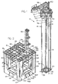
- the platform 12 includes four vertically extending comer columns 116, 117, 118 and 119 lying at the corners of an imaginary rectangle (which is preferably substantially a square).
- Four horizontal beams 121, 122, 123 and 124 each connect the lower ends 125 of a different pair of columns.
- Each of the columns and beams 116-119 and 121-124 has an average width W of a plurality of feet (e.g. 7 meters), with the particular columns and beams shown having an average width of over one meter, and all form at least one chamber which can hold water or air to change the ballast condition of the platform.
- a beam structure 126 comprising multiple steel beams (none forms a hollow water-filled chamber), connects the upper ends 127 of the columns.
- Each column such as column 116 shown in FIG. 3 has a plurality of vertically spaced chambers with a horizontal separating wall 128.
- the separating wall is part of the column structure.
- FIG. 6 shows an oil production complex 130 which includes the system 10 of FIG. 1. Oil passing up through the risers 34 and into the trees on the platform 12, is gathered and passed through pipes lying within a conduit 132 that extends to a large vessel 134.
- the large vessel 134 may be a tanker with large oil-storing capacity, and which also has hydrocarbon processing equipment 136, permanent (nonemergency crew quarters where personnel stay for many days under normal operating conditions), offloading equipment for transferring oil to other tankers, life boats, etc. If the platform has any hydrocarbon processing equipment, it is minimal in that the mass of processing equipment on the vessel is at last 5 times as great.
- the vessel supports a turret 140 that can remain stationary (not rotate much, but only drift) while the vessel weathervanes around it, and the vessel is moored by catenary anchor chains 142.
- the anchor chains allow the vessel to drift only a moderate amount such as 300 meters.
- the platform 12 lies in water having a depth of 1,000 meters and the space between the vessel 134 and platform is at least 500 meters. It is noted that the fluid conduit 132 includes two sections, With a buoy 144 connecting them.
- TLP system 10 Systems for anchoring large vessels such as 134 while allowing them to drift, are of only moderate cost.
- Applicant's TLP system 10 is of relatively small size, so it is also of moderate cost.
- Servicing of the platform 12 is done by relatively small boats 146 carried by crew members stationed on the vessel 134.
- crew members may carry air pumps and various equipment for maintaining parts of the system 10, and also serve to operate a tender assisted workover rig 150 which can carry out well completion, workover and redrilling.
- the rig 150 can be shifted around the TLP on skids, which is well known to the industry.
- Fig. 2 shows the drilling rig shifted away from the center (axis 109 in Fig. 3) of the platform to lie over one of the apertures (40A-40F).
- 400 tons 360 MT, which is at least 5% of tendon and riser tension.
- Applicant compensates for the change in center of gravity (and center of buoyancy) caused by such movement by reducing buoyancy at the previous rig location (by admitting water into buoyancy chambers near the previous rig location) and/or by adding buoyancy at the new rig location (by removing water from buoyancy chambers near the new rig location). This is because tension elements (tendons and any already-installed risers) are spaced about the platform axis 152, and such compensation minimizes changes in tension of such tension elements due to such rig movement.
- applicant provides a relatively low costTLP system. This is accomplished by using a relatively small platform and relatively light duty tendons that hold it in place, together with moderately large risers (requiring moderately large tension) which may be connected singly or in small groups, with the system designed to operate for indefinite periods and even in storms, between riser additions.
- the platform is provided with buoyancy adjusting means in the form of chambers which are initially flooded but which can be partially or completely filled with gas instead of water to increase platform buoyancy. Such ability to increase platform buoyancy in steps, allows applicant to easily adjust for the additional tension produced by the addition of each riser. This allows for the use of a relatively light weight platform and relatively light weight tendons, which greatly reduces the cost of the system.
- the light weight platform preferably has only minimal equipment, including a tree for each riser, possibly a mount for holding a derrick, and minimal couplings and piping.
Landscapes
- Earth Drilling (AREA)
Claims (7)
- Trossenverspanntes Bohrplattformsystem, das eine Plattform (12), die auf der Meeresoberfläche schwimmt und eine vertikale Achse (109) aufweist, eine Vielzahl von Vorspanngliedern (16), die sich von der Plattform zum Meeresboden (26) hinunter erstrecken und dort verankert sind, sowie einen Bohrturm (150) umfasst, der auf der Plattform liegt, wobei die Plattform Mittel (50, 56) aufweist, um bis zu einer maximalen Anzahl von Steigleitungen (34) zu befestigen, und eine Vielzahl von Steigleitungen (34) beinhaltet, die sich jeweils von der Plattform zum Meeresboden hinunter erstrecken und dort verankert sind, wobei die Vorspannglieder und die Steigleitungen jeweils unter Spannung gehalten werden, wodurch abwärts gerichtete Kräfte auf die Plattform erzeugt werden, denen durch eine Verlagerung der Plattform entgegenwirkt wird, dadurch gekennzeichnet, dassder Bohrturm ein Gewicht aufweist, das zumindest 5 % der Spannung der Vorspannglieder und der Steigleitungen ausmacht, und horizontal um die Plattform verschoben werden kann,der Auftrieb der Plattform klein genug ist und die Vorspannglieder ausreichend Spannung aufweisen, damit die kombinierte abwärts gerichtete Kraft, die von den Vorspanngliedern und der vorbestimmten Anzahl von Steigleitungen auf die Plattform ausgeübt wird, zumindest 20 % der Arbeitsverlagerung der Plattform ausmacht; unddie Plattform eine Vielzahl einstellbarer Auftriebskammern (90, 92, 94) aufweist, die um die vertikale Achse und die Vorrichtung (100, 106) beabstandet sind, um den Auftrieb der Kammern so zu steuern, dass eine annähernd konstante Vorspannglied-Spannung in allen Vorspanngliedern beibehalten wird, wenn der Bohrturm verschoben wird.
- System nach Anspruch 1, worin:die Plattform eine horizontale Breite und eine horizontale Länge aufweist, wobei der Bohrturm horizontal von einer Position über der Achse weg bewegt werden kann und die Auftriebskammern für die Bewegung des Turms eingestellt werden können, um Veränderungen der Vorspannglied-Spannung zu vermeiden.
- System nach Anspruch 1, worin:die Plattform vier vertikale Ecksäulen (116, 117, 118, 119) mit oberen (127) und unteren (125) Endabschnitten, eine Struktur (126), die die oberen Endabschnitte miteinander verbindet, wobei der Bohrturm beweglich auf der Struktur montiert ist, sowie vier horizontale Träger (121, 122, 123, 124) umfasst, die die unteren Endabschnitte der Säulen miteinander verbinden, wobei jede der Säulen und jeder der Träger zumindest einen Abschnitt einer der Auftriebskammern aufweisen.
- System nach Anspruch 3, worin:eine Vielzahl der Träger zumindest eine Öffnung (40, 40A-40F) aufweist, wobei der Bohrturm so verschiebbar ist, dass er sich über eine beliebige der Öffnungen bewegt.
- System nach Anspruch 3, worin:die Säulen und die Träger jeweils zumindest Abschnitte von Kammern (90, 92, 94) mit einstellbarem Auftrieb aufweisen, deren Auftrieb eingestellt werden kann, um Veränderungen der Spannungen der Vorspannglieder zu kompensieren, die aus der Verschiebung des Bohrturms resultieren.
- Verfahren zum Betreiben einer trossenverspannten Bohrplattform (10), die eine Achse (109), einen Bohrturm (150), der horizontal auf der Plattform verschoben werden kann, eine Vielzahl einstellbarer Auftriebskammern, die um die Achse beabstandet sind, sowie eine Vielzahl von Vorspanngliedern und zumindest eine Steigleitung aufweist, die sich alle vertikal von der Plattform zum Meeresboden erstrecken und im Meeresboden verankert sind, umfassend:das horizontale Verschieben des Bohrturms auf der Plattform und das Einstellen des Auftriebs der Kammern, um eine im Wesentlichen konstante Spannung in den Vorspanngliedern und der zumindest einen Steigleitung beizubehalten.
- Verfahren nach Anspruch 6, worin:die Plattform eine Vielzahl von Öffnungen (40A-40F) aufweist, die horizontal von der Achse beabstandet sind, wobei der Bohrturm so bewegt werden kann, dass er über einer ausgewählten der Öffnungen liegt, und der Schritt des Einstellens das Einfüllen von Wasser in zumindest eine der Auftriebskammern, um ihren Auftrieb zu verringern, sowie das Ausblasen von Wasser umfasst, um den Auftrieb einer anderen der Auftriebskammern zu erhöhen.
Applications Claiming Priority (1)
| Application Number | Priority Date | Filing Date | Title |
|---|---|---|---|
| PCT/US1996/012639 WO1998005825A1 (en) | 1994-12-14 | 1996-08-02 | Tlp tension adjust system |
Publications (3)
| Publication Number | Publication Date |
|---|---|
| EP0916006A1 EP0916006A1 (de) | 1999-05-19 |
| EP0916006A4 EP0916006A4 (de) | 2001-10-17 |
| EP0916006B1 true EP0916006B1 (de) | 2003-10-29 |
Family
ID=22255546
Family Applications (1)
| Application Number | Title | Priority Date | Filing Date |
|---|---|---|---|
| EP96928044A Expired - Lifetime EP0916006B1 (de) | 1996-08-02 | 1996-08-02 | SPANNUNGSREGELUNG FüR EINE PLATTFORM MIT SPANNBEINEN |
Country Status (2)
| Country | Link |
|---|---|
| EP (1) | EP0916006B1 (de) |
| BR (1) | BR9612701A (de) |
-
1996
- 1996-08-02 BR BR9612701A patent/BR9612701A/pt active IP Right Grant
- 1996-08-02 EP EP96928044A patent/EP0916006B1/de not_active Expired - Lifetime
Also Published As
| Publication number | Publication date |
|---|---|
| BR9612701A (pt) | 1999-08-03 |
| EP0916006A4 (de) | 2001-10-17 |
| EP0916006A1 (de) | 1999-05-19 |
Similar Documents
| Publication | Publication Date | Title |
|---|---|---|
| US6375391B1 (en) | Guide device for production risers for petroleum production with a “dry tree semisubmersible” at large sea depths | |
| US5433273A (en) | Method and apparatus for production of subsea hydrocarbon formations | |
| US4702321A (en) | Drilling, production and oil storage caisson for deep water | |
| US6227137B1 (en) | Spar platform with spaced buoyancy | |
| US6691784B1 (en) | Riser tensioning system | |
| US6309141B1 (en) | Gap spar with ducking risers | |
| US5964550A (en) | Minimal production platform for small deep water reserves | |
| US4114393A (en) | Lateral support members for a tension leg platform | |
| US4966495A (en) | Semisubmersible vessel with captured constant tension buoy | |
| US5575592A (en) | TLP tension adjust system | |
| US6170424B1 (en) | Production/platform mooring configuration | |
| US6336421B1 (en) | Floating spar for supporting production risers | |
| WO2008022119A2 (en) | Floating offshore drilling/producing structure | |
| US20040028479A1 (en) | Vertically restrained centerwell SPAR | |
| WO2005051755A2 (en) | Buoyancy can for offshore oil and gas riser | |
| US6106198A (en) | Method for installation of tension-leg platforms and flexible tendon | |
| US6688250B2 (en) | Method and apparatus for reducing tension variations in mono-column TLP systems | |
| US5997218A (en) | Method of and apparatus for stabilizing a tension-leg platform in deep water operations | |
| US20020115365A1 (en) | Buoyancy module with external frame | |
| GB2180809A (en) | Tethered buoyant system | |
| EP0916006B1 (de) | SPANNUNGSREGELUNG FüR EINE PLATTFORM MIT SPANNBEINEN | |
| WO1997029942A1 (en) | Stopper chain locking mechanism for tension-leg platform tendons | |
| EP1163422A1 (de) | Einrichtung mit führungsrahmen für eine ölsteigleitung; führungsrahmen für steigleitungen; schwimmelement für steigleitungen und eine halbversenkbare produktionsplattform | |
| Wanvik et al. | Deep water moored semisubmersible with dry wellheads and top tensioned well risers | |
| RU2773250C2 (ru) | Плавучая система и способ с плавучей надставкой и направляющей трубой |
Legal Events
| Date | Code | Title | Description |
|---|---|---|---|
| PUAI | Public reference made under article 153(3) epc to a published international application that has entered the european phase |
Free format text: ORIGINAL CODE: 0009012 |
|
| 17P | Request for examination filed |
Effective date: 19990219 |
|
| AK | Designated contracting states |
Kind code of ref document: A1 Designated state(s): FR GB NL |
|
| A4 | Supplementary search report drawn up and despatched |
Effective date: 20010831 |
|
| AK | Designated contracting states |
Kind code of ref document: A4 Designated state(s): FR GB NL |
|
| 17Q | First examination report despatched |
Effective date: 20020715 |
|
| GRAH | Despatch of communication of intention to grant a patent |
Free format text: ORIGINAL CODE: EPIDOS IGRA |
|
| GRAS | Grant fee paid |
Free format text: ORIGINAL CODE: EPIDOSNIGR3 |
|
| GRAA | (expected) grant |
Free format text: ORIGINAL CODE: 0009210 |
|
| AK | Designated contracting states |
Kind code of ref document: B1 Designated state(s): FR GB NL |
|
| REG | Reference to a national code |
Ref country code: GB Ref legal event code: FG4D |
|
| ET | Fr: translation filed | ||
| PLBE | No opposition filed within time limit |
Free format text: ORIGINAL CODE: 0009261 |
|
| STAA | Information on the status of an ep patent application or granted ep patent |
Free format text: STATUS: NO OPPOSITION FILED WITHIN TIME LIMIT |
|
| 26N | No opposition filed |
Effective date: 20040730 |
|
| PGFP | Annual fee paid to national office [announced via postgrant information from national office to epo] |
Ref country code: NL Payment date: 20130826 Year of fee payment: 18 |
|
| PGFP | Annual fee paid to national office [announced via postgrant information from national office to epo] |
Ref country code: GB Payment date: 20130827 Year of fee payment: 18 |
|
| REG | Reference to a national code |
Ref country code: NL Ref legal event code: V1 Effective date: 20150301 |
|
| GBPC | Gb: european patent ceased through non-payment of renewal fee |
Effective date: 20140802 |
|
| PG25 | Lapsed in a contracting state [announced via postgrant information from national office to epo] |
Ref country code: NL Free format text: LAPSE BECAUSE OF NON-PAYMENT OF DUE FEES Effective date: 20150301 |
|
| REG | Reference to a national code |
Ref country code: FR Ref legal event code: PLFP Year of fee payment: 20 |
|
| PG25 | Lapsed in a contracting state [announced via postgrant information from national office to epo] |
Ref country code: GB Free format text: LAPSE BECAUSE OF NON-PAYMENT OF DUE FEES Effective date: 20140802 |
|
| PGFP | Annual fee paid to national office [announced via postgrant information from national office to epo] |
Ref country code: FR Payment date: 20150727 Year of fee payment: 20 |