EP1563160B1 - Spannungssystem zur herstellung von rohrleitungen in einem steigrohr an einer schwimmenden anlage zur kohlenwasserstoffgewinnung - Google Patents
Spannungssystem zur herstellung von rohrleitungen in einem steigrohr an einer schwimmenden anlage zur kohlenwasserstoffgewinnung Download PDFInfo
- Publication number
- EP1563160B1 EP1563160B1 EP03813033A EP03813033A EP1563160B1 EP 1563160 B1 EP1563160 B1 EP 1563160B1 EP 03813033 A EP03813033 A EP 03813033A EP 03813033 A EP03813033 A EP 03813033A EP 1563160 B1 EP1563160 B1 EP 1563160B1
- Authority
- EP
- European Patent Office
- Prior art keywords
- riser
- production tubing
- tubing
- production
- accordance
- Prior art date
- Legal status (The legal status is an assumption and is not a legal conclusion. Google has not performed a legal analysis and makes no representation as to the accuracy of the status listed.)
- Expired - Lifetime
Links
Images
Classifications
-
- E—FIXED CONSTRUCTIONS
- E21—EARTH OR ROCK DRILLING; MINING
- E21B—EARTH OR ROCK DRILLING; OBTAINING OIL, GAS, WATER, SOLUBLE OR MELTABLE MATERIALS OR A SLURRY OF MINERALS FROM WELLS
- E21B33/00—Sealing or packing boreholes or wells
- E21B33/02—Surface sealing or packing
- E21B33/03—Well heads; Setting-up thereof
- E21B33/04—Casing heads; Suspending casings or tubings in well heads
- E21B33/043—Casing heads; Suspending casings or tubings in well heads specially adapted for underwater well heads
-
- E—FIXED CONSTRUCTIONS
- E21—EARTH OR ROCK DRILLING; MINING
- E21B—EARTH OR ROCK DRILLING; OBTAINING OIL, GAS, WATER, SOLUBLE OR MELTABLE MATERIALS OR A SLURRY OF MINERALS FROM WELLS
- E21B19/00—Handling rods, casings, tubes or the like outside the borehole, e.g. in the derrick; Apparatus for feeding the rods or cables
- E21B19/002—Handling rods, casings, tubes or the like outside the borehole, e.g. in the derrick; Apparatus for feeding the rods or cables specially adapted for underwater drilling
- E21B19/004—Handling rods, casings, tubes or the like outside the borehole, e.g. in the derrick; Apparatus for feeding the rods or cables specially adapted for underwater drilling supporting a riser from a drilling or production platform
- E21B19/006—Handling rods, casings, tubes or the like outside the borehole, e.g. in the derrick; Apparatus for feeding the rods or cables specially adapted for underwater drilling supporting a riser from a drilling or production platform including heave compensators
Definitions
- This invention regards a tensioning device for production tubing installed in a riser connecting a subsea hydrocarbon well with a floating installation on the surface of the sea, in particular a system for tensioning the fixed part of the production tubing and relieving it by suspending it from the fixed part of the riser, and also maintaining tension in that part of the production tubing which passes through a telescopic riser unit up to the production deck, by connecting a counterweight to the production tubing by means of a wire suspended from a pulley in the derrick.
- the well and the floating installation are usually interconnected by several connecting pipes, among other things production tubing through which hydrocarbons flow up from the well.
- Several pipes may be gathered in a so-called riser of a dimension suitable for the purpose.
- the actual riser is kept under tension by means of a riser tensioner attached to the floating installation.
- the upper section of the riser comprises a telescopic section, which in some cases is combined with the riser tensioner.
- Some of the pipe connections inside the riser may have a similar telescopic section.
- the production tubing Under normal circumstances, it is not desirable for the production tubing to comprise a telescopic section. As a result, this is normally passed rigidly through the telescopic section of the riser and up to the production deck of the installation, where it is suspended from the tensioning system via wires, which tensioning system consists of pulleys and cylinders interconnected in a manner such as to maintain the tension in the production tubing regardless of the movements of the installation on the surface of the sea.
- the object of the invention is to remedy the disadvantages of prior art.
- the tension in a riser is maintained in a manner that is known per se, by use of a tensioner comprising e.g. a tension collar attached to an upper section of the riser and further connected via wires to a system of pulleys and cylinders suitable for maintaining a prescribed tension in the riser.
- a tensioner comprising e.g. a tension collar attached to an upper section of the riser and further connected via wires to a system of pulleys and cylinders suitable for maintaining a prescribed tension in the riser.
- the tension may be maintained by a combined telescopic and tensioning device mounted in the extension of the upper part of the riser.
- a tubing tensioner unit is interposed between a telescopic section and the upper section of the riser.
- a connection from the well via the production tubing passes centrally through the tubing tensioner unit.
- the tubing tensioner unit primarily comprises a housing and a tubular cylinder.
- the housing of the tubing tensioner unit is essentially a concentric tube, the end portions of which are provided with flanges suitable for complementary connection to the upper section of the riser located below and the lower end of the telescopic section located above. Said parts are rigidly mounted to each flange connection with the use of several bolts.
- the tubular cylinder comprises a piston section and a cylinder section.
- the piston section comprises a tube with an inner diameter essentially equal to the dimension of the production tubing for which the tubing tensioner unit is intended.
- a middle section of the tube is provided with a concentric piston with a diameter considerably greater than the outer diameter of the tube.
- the piston section is connected to the production tubing sections located above and below, by use of threaded connecting sockets that are known per se.
- the piston casing is provided with appropriate packings.
- the cylinder section comprises a cylinder and lower and upper gables with associated packings in concentric openings that match the outer diameter of the piston section.
- the inner diameter of the cylinder is adapted to the outer piston diameter of said piston section.
- the upper gable of the cylinder section is removable through being provided with male threads that correspond to female threads in the cylinder.
- the tube and its piston are arranged inside the cylinder section with the ends of the tube projecting from the gables of the cylinder.
- the piston divides the cylinder into an upper and a lower chamber.
- the lower gable of the cylinder section comprises a cylindrical portion that extends down from the end of the cylinder.
- the casing of the cylindrical portion is provided with several recesses each designed to accommodate a ratchet suspended in a swivelling manner from the upper end portion of the ratchet.
- the ratchet swivels out primarily in a radial direction from the cylindrical gable portion, so that the lower portion of the ratchet projects from the gable portion.
- the lower end face of the ratchet points downwards at an angle and out from its border against the inside face of the ratchet.
- the ratchets are essentially spaced evenly and concentrically around the gable portion.
- Each ratchet is provided with means of exerting a pressure against the inside of the ratchet, e.g. in the form of a compression spring, so that the ratchet swings out from its recess when the space outside the ratchets is unobstructed.
- the cylinder section is provided with an inlet for supply of fluid, e.g. hydraulic oil, to the lower chamber of the cylinder.
- the inlet is connected to a hydraulic unit that is known per se, complete with pump, reservoir and control devices, in a manner that is known per se.
- the inside wall of the housing of the tubing tensioner unit is provided with an annular recess designed to leave room for the protruding ratchets of the gable portion when the cylinder has been inserted into the housing of the tubing tensioner unit.
- a lower edge of the recess faces down and out at an angle from its border against the housing wall surface. The orientation of the lower edge typically coincides with the lower end face of the ratchets when the ratchets have been swung into the annular recess.
- the housing of the tubing tensioner unit is coupled to the riser at a suitable height above the seabed, whereupon the telescopic section is coupled to the upper end of the housing by means of the appropriate flanges.
- the production tubing is assembled and lowered successively through the riser.
- the tubular cylinder is connected to the production tubing at an appropriate distance from the lower end of the production tubing, to allow the tubular cylinder to assume its position in said housing when the lower end of the production tubing is connected to the wellhead installation on the seabed.
- the axial position of the cylinder on the production tubing, which has been extended by the piston section of the tubular cylinder is adjusted so as to make the ratchets on the tubular cylinder engage the annular recess in the housing.
- the lower chamber of the tubular cylinder is pressurised hydraulically by means of the hydraulic unit. This tensions the production tubing, as the reaction forces from the tubular cylinder are transferred to the riser via the ratchets and the housing of the tubing tensioner, which is placed at the top of the riser.
- a production tubing extension Connected to the top of the riser is a production tubing extension which runs continuously through a telescopic unit that is known per se, and up above the production deck of the installation.
- the upper end portion of the production tubing extension is connected to one end of a wire in a manner that is known per se .
- the wire is passed over a pulley device arranged considerably higher than the production deck, e.g. in the derrick.
- the other end of the wire is connected to a freely suspended counterweight with a mass adapted to the weight of the production tubing extension.
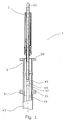
- reference number 1 denotes a tubing tensioner unit consisting of a tubular cylinder 3 and a housing 5, see figure 1.
- the tubular cylinder 3 consists of a cylinder 7, an upper gable 9 and a lower gable 11. Both gables 9, 11 have a central circular opening 13 provided with several packings 15.
- the upper gable 9 is provided with a through air passage 17 and a hydraulic passage 19 for introduction of hydraulic fluid to the tubular cylinder 1.
- the hydraulic passage 19 follows the wall of the cylinder 7 and ends up in the tubular cylinder by the lower gable 11.
- the lower gable 11 extends cylindrically out from the cylinder 7 in the axial direction, with a diameter that substantially is slightly larger than the outer diameter of the cylinder 7.
- the jacket 21 of the lower gable 11 is provided with several uniform cutouts 23.
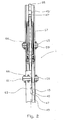
- a ratchet 25 is suspended from the gable 11 in a swivelling manner with an axle 27 through an upper part 29 of the ratchet 25.
- a longitudinal section through the ratchet and in the radial direction of the gable 11 shows the thickness of the ratchet 25 as decreasing from the lower part 31 to the upper part 29.
- An inner ratchet face 33 is provided with a recess 35.
- a lower ratchet face 37 extends away from the inner ratchet face 33 and partly downwards at an angle.
- the cutout 23 has a recess 39 corresponding to the recess 35 in the ratchet 25.
- a spring device 41 capable of forcing the ratchet out is arranged with its ends in the recesses 35, 39.
- a tubular piston rod 43 with end portions 45 threaded at both ends has an internal diameter of the same order as on a production tubing 49.
- the end portion 47 of the production tubing 49 is threaded correspondingly, and two corresponding end portions 45, 47 are joined with a sleeve 48 provided with female threads.
- the piston rod is provided with a concentric piston 53 that corresponds to the inner diameter of the cylinder 7.
- the piston 53 is provided with appropriate packings 55.
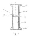
- the housing 5 of the tubing tensioner unit comprises an essentially tubular main section 57 plus a flange 59, 59' placed at either end, which corresponds with a flange 61 on a riser 63 and a flange 65 on a telescopic unit 67.
- the flanges 59, 59', 61, 65 are connected with several through bolts 66.
- the main section 57 of the housing 5 is provided with an annular concentric recess 69 positioned approximately halfway between the flanges 59, 59' of the housing 5.
- a lower face 71 of the recess slopes slightly downwards from the inner wall 73 of the housing, so that the direction of the face 71 coincides with that of the lower ratchet face 37 (see figure 3) when the ratchet 25 is forced out from the cutout 23 in the lower gable 11.
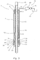
- the tubular cylinder 1 is connected via the hydraulic passage 19 to a hydraulic unit 75 that is known per se (shown schematically), and which comprises pipe 77, reservoir 79, pump 81 and control device 83.
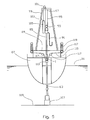
- a production tubing extension 85 is connected to the upper end portion 45 of the tubular cylinder 3 and projects above the production deck 89 of a floating installation 87, where the tubing extension 85 is coupled to a flexible hose 91 and a pulley 93.
- a wire 95 is attached to a tower 99, e.g. a derrick, by its first end 97, and is then passed down to and through the pulley 93 and up to and over a fixed pulley 101, and then down in the direction of the production deck 89.
- the other end 103 of the wire 95 is attached to a counterweight 105.
- a riser 63 extends from a wellhead installation 107 on the seabed 109 and up towards the installation 87 floating on the surface of the sea 111.
- the riser is suspended from several tensioning wires 115 at a collar 113, which wires are connected via pulleys 117 to riser tensioners 119.
- the tension in the wires 115 is maintained by means of regulating devices (not shown).
- the housing 5 is connected by its one flange 59 to the flange 61 on the riser 63, through use of bolts 66.
- the riser 63 is then completed with the telescopic unit 67 that is connected to the upper flange 59' of the housing 5 by means of bolts 66.
- the riser 63 is kept under tension by means of the riser tensioners 119.
- a prescribed tension in the wires 115 is maintained by means of the regulating devices (not shown) that actuate the riser tensioners 119.
- the production tubing 49 passes from the floating installation 87 down through the riser 63 to the wellhead installation 107.
- the tubular cylinder 3 is connected to the upper end of the production tubing 49 by means of the corresponding coupling devices 45, 47.
- the length of the production tubing 49 is adjusted in relation to the position of the housing 5 on the riser 63, so that the ratchets 25 on the tubular cylinder 3 to all intents and purposes correspond with the annular recess 69 of the housing 5 when the production tubing 49 is lowered all the way to the wellhead installation 107 on the seabed 109.
- the production tubing extension 85 is connected to the upper end of the tubular cylinder 3 by means of the corresponding coupling devices 45', 47'.
- the cylinder 7 with its flanges 9, 11 is then displaced up or down along the piston rod 43 until the ratchets 25 are forced out into the internal recess 69 of the housing 5 and abut the lower faces 71 of the recess 69.
- the upper end of the tubing extension 85 is connected to the counterweight 105, so as to allow the counterweight 105 to keep the tension in the production tubing extension 85 by means of the pulleys 93, 101 and the wire 95.
- the piston 53 will subsequently seek to stretch the production tubing 49, the ratchets 25 ensuring that the cylinder 7 and its gables 9, 11 rest on the face 71 in the housing 5.
- the reaction forces from the tubular cylinder 3 are thereby transferred to the riser 63.
- the part of the production tubing 49 extending from the hydrocarbon well 107 up to the tubing tensioner unit 1 is stretched and suspended from the riser 63. Consequently only the upper part of the production tubing 49, i.e. the production tubing extension 85, has to be suspended from a tensioning device on the floating installation 87, and then in the form of the simple arrangement consisting of the counterweight 105, the wire 95 and the pulleys 93, 101.
Landscapes
- Engineering & Computer Science (AREA)
- Geology (AREA)
- Mining & Mineral Resources (AREA)
- Life Sciences & Earth Sciences (AREA)
- General Life Sciences & Earth Sciences (AREA)
- Fluid Mechanics (AREA)
- Environmental & Geological Engineering (AREA)
- Physics & Mathematics (AREA)
- Geochemistry & Mineralogy (AREA)
- Mechanical Engineering (AREA)
- Earth Drilling (AREA)
- Supports For Pipes And Cables (AREA)
- Rigid Pipes And Flexible Pipes (AREA)
- Pipeline Systems (AREA)
- Lubricants (AREA)
Claims (8)
- Vorrichtung zum Spannen und Entlasten einer Produktionsrohrleitung (49), die sich von einem unterseeischen Ölbohrloch (107) durch eine Steigrohrleitung (63) zu einer schwimmenden Anlage (87) nach oben erstreckt, wobei eine kontinuierliche Produktionsrohrleitungsverlängerung (85) durch eine Teleskopeinheit (67) im oberen Bereich der Steigrohrleitung (63) tritt und sich vorzugsweise oberhalb eines Produktionsdecks (89) der schwimmenden Anlage (87) erstreckt, dadurch gekennzeichnet, dass die Produktionsrohrleitung (49) mit einer Rohrleitungsspanneinheit (1) unterhalb und in der Nähe des unteren Endes der Teleskopeinheit (67) versehen ist.
- Vorrichtung nach Anspruch 1, dadurch gekennzeichnet, dass die Rohrleitungsspanneinheit (1) Mittel (3, 5, 25, 41, 69) zum Verbinden der Produktionsrohrleitung (49) mit der Steigrohrleitung (63) umfasst.
- Vorrichtung nach Anspruch 1, dadurch gekennzeichnet, dass die Rohrleitungsspanneinheit (1) einen rohrförmigen Zylinder (3) umfasst, der mit mehreren mit Sprungfedern versehenen Klinken (25, 41) ausgestattet ist, die zum Eingreifen in eine untere Fläche (71) einer ringförmigen inneren Ausnehmung (69) eines in die Steigrohrleitung (63) integrierten Gehäuses (5) vorgesehen sind.
- Vorrichtung nach einem oder mehreren der vorangehenden Ansprüche, dadurch gekennzeichnet, dass die Rohrleitungsspanneinheit (1) Mittel (3, 75) zum Aufrechterhalten eines Spannungsbetrags in der Produktionsrohrleitung (49) umfasst.
- Vorrichtung nach einem oder mehreren der vorangehenden Ansprüche, dadurch gekennzeichnet, dass der rohrförmige Zylinder (3) mit einer rohrförmigen Kolbenstange (43) ausgestattet ist, die Kupplungsmittel (45) zum Verbinden mit entsprechenden Kupplungsmitteln (47, 48) an der Produktionsrohrleitung (49) und der Produktionsrohrleitungsverlängerung (85) umfasst.
- Vorrichtung nach einem oder mehreren der vorangehenden Ansprüche, dadurch gekennzeichnet, dass der rohrförmige Zylinder (3) zum Aufnehmen eines hydraulischen Drucks in einer Zylinderkammer unterhalb eines Kolbens (53) vorgesehen ist.
- Vorrichtung nach einem oder mehreren der vorangehenden Ansprüche, dadurch gekennzeichnet, dass ein oberes Endteil der Produktionsrohrleitungsverlängerung (85) mit einer Spannvorrichtung (93, 97, 99, 101, 105) verbunden ist.
- Vorrichtung nach Anspruch 7, dadurch gekennzeichnet, dass die Rohrleitungsspanneinheit (1) mehrere Rollen (93, 101), ein oder mehrere Kabel (95) und ein oder mehrere Gegengewichte (105) umfasst.
Applications Claiming Priority (3)
| Application Number | Priority Date | Filing Date | Title |
|---|---|---|---|
| NO20025556 | 2002-11-20 | ||
| NO20025556A NO317231B1 (no) | 2002-11-20 | 2002-11-20 | Strammesystem for produksjonsror i et stigeror ved en flytende installasjon for hydrokarbonproduksjon |
| PCT/NO2003/000384 WO2004057147A2 (en) | 2002-11-20 | 2003-11-13 | Tensioning system for production tubing in a riser at a floating installation for hydrocarbon production. |
Publications (2)
| Publication Number | Publication Date |
|---|---|
| EP1563160A2 EP1563160A2 (de) | 2005-08-17 |
| EP1563160B1 true EP1563160B1 (de) | 2006-06-07 |
Family
ID=19914196
Family Applications (1)
| Application Number | Title | Priority Date | Filing Date |
|---|---|---|---|
| EP03813033A Expired - Lifetime EP1563160B1 (de) | 2002-11-20 | 2003-11-13 | Spannungssystem zur herstellung von rohrleitungen in einem steigrohr an einer schwimmenden anlage zur kohlenwasserstoffgewinnung |
Country Status (11)
| Country | Link |
|---|---|
| US (1) | US7188677B2 (de) |
| EP (1) | EP1563160B1 (de) |
| AT (1) | ATE329126T1 (de) |
| AU (1) | AU2003303117A1 (de) |
| BR (1) | BR0313558B1 (de) |
| CA (1) | CA2494283C (de) |
| DE (1) | DE60305965T2 (de) |
| DK (1) | DK1563160T3 (de) |
| MX (1) | MXPA05005043A (de) |
| NO (1) | NO317231B1 (de) |
| WO (1) | WO2004057147A2 (de) |
Cited By (1)
| Publication number | Priority date | Publication date | Assignee | Title |
|---|---|---|---|---|
| DE102006019261B4 (de) * | 2006-04-26 | 2009-01-15 | Klemm Bohrtechnik Zweigniederlassung Der Bauer Maschinen Gmbh | Bohrgerät mit beweglicher Lünette |
Families Citing this family (17)
| Publication number | Priority date | Publication date | Assignee | Title |
|---|---|---|---|---|
| FR2857690B1 (fr) * | 2003-07-15 | 2005-08-26 | Inst Francais Du Petrole | Systeme de forage en mer comprenant une colonne montante haute pression |
| GB0613393D0 (en) * | 2006-07-06 | 2006-08-16 | Enovate Systems Ltd | Improved workover riser compensator system |
| US20080187401A1 (en) * | 2007-02-02 | 2008-08-07 | Tom Bishop | Riser tensioner for an offshore platform |
| US8333243B2 (en) * | 2007-11-15 | 2012-12-18 | Vetco Gray Inc. | Tensioner anti-rotation device |
| EP2650465A1 (de) * | 2008-04-10 | 2013-10-16 | Weatherford/Lamb Inc. | Landestrangkompensator |
| AU2012201418B2 (en) * | 2008-04-10 | 2015-04-09 | Weatherford Technology Holdings, Llc | Landing string compensator |
| EP2186993B1 (de) * | 2008-11-17 | 2019-06-26 | Saipem S.p.A. | Fahrzeug zum arbeiten an unterseeischen bohrlöchern und arbeitsverfahren |
| US8387707B2 (en) * | 2008-12-11 | 2013-03-05 | Vetco Gray Inc. | Bellows type adjustable casing |
| US8393397B2 (en) * | 2010-03-17 | 2013-03-12 | Halliburton Energy Services, Inc. | Apparatus and method for separating a tubular string from a subsea well installation |
| NO334739B1 (no) * | 2011-03-24 | 2014-05-19 | Moss Maritime As | System for trykkontrollert boring eller for brønnoverhaling av en hydrokarbonbrønn og en fremgangsmåte for oppkobling av et system for trykkontrollert boring eller for brønnoverhaling av en hydrokarbonbrønn |
| US10060207B2 (en) * | 2011-10-05 | 2018-08-28 | Helix Energy Solutions Group, Inc. | Riser system and method of use |
| BR112014014735A2 (pt) * | 2011-12-19 | 2017-06-13 | Cameron Int Corp | sistema de perfuração de poço offshore com risers de perfuração aninhados |
| US9133670B2 (en) * | 2012-07-26 | 2015-09-15 | Cameron International Corporation | System for conveying fluid from an offshore well |
| BR112015023615A2 (pt) | 2013-03-15 | 2017-07-18 | Ameriforge Group Inc | conjunto de elevação de perfuração |
| CN105625949A (zh) * | 2014-11-03 | 2016-06-01 | 上海海郑海洋建设工程技术有限公司 | 隔水管、海上钻井系统 |
| CN110300834B (zh) | 2017-01-18 | 2022-04-29 | 米尼克斯Crc有限公司 | 一种移动式连续油管钻井装置 |
| CN109098675A (zh) * | 2018-10-15 | 2018-12-28 | 西南石油大学 | 一种用于海洋平台钻井的被动式深海升深沉补偿装置 |
Family Cites Families (17)
| Publication number | Priority date | Publication date | Assignee | Title |
|---|---|---|---|---|
| GB1077284A (en) * | 1965-10-19 | 1967-07-26 | Shell Int Research | Method and apparatus for carrying out operations on a well under water |
| US3681928A (en) * | 1970-09-15 | 1972-08-08 | Leonardus M J Vincken | Method and apparatus for carrying out underwater well operations |
| US4272059A (en) * | 1978-06-16 | 1981-06-09 | Exxon Production Research Company | Riser tensioner system |
| US4258792A (en) * | 1979-03-15 | 1981-03-31 | Otis Engineering Corporation | Hydraulic tubing tensioner |
| US4432420A (en) * | 1981-08-06 | 1984-02-21 | Exxon Production Research Co. | Riser tensioner safety system |
| US4702320A (en) * | 1986-07-31 | 1987-10-27 | Otis Engineering Corporation | Method and system for attaching and removing equipment from a wellhead |
| NO169027C (no) * | 1988-11-09 | 1992-04-29 | Smedvig Ipr As | Bevegelseskompensator for stigeroer |
| US5479990A (en) * | 1992-09-28 | 1996-01-02 | Shell Oil Company | Rising centralizing spider |
| US5524710A (en) * | 1994-12-21 | 1996-06-11 | Cooper Cameron Corporation | Hanger assembly |
| US6283208B1 (en) * | 1997-09-05 | 2001-09-04 | Schlumberger Technology Corp. | Orienting tool and method |
| US5944111A (en) * | 1997-11-21 | 1999-08-31 | Abb Vetco Gray Inc. | Internal riser tensioning system |
| US6913092B2 (en) * | 1998-03-02 | 2005-07-05 | Weatherford/Lamb, Inc. | Method and system for return of drilling fluid from a sealed marine riser to a floating drilling rig while drilling |
| US6293345B1 (en) * | 1998-03-26 | 2001-09-25 | Dril-Quip, Inc. | Apparatus for subsea wells including valve passageway in the wall of the wellhead housing for access to the annulus |
| NO308379B1 (no) | 1998-12-08 | 2000-09-04 | Hitec Asa | StrekkpÕkjennende og hivkompenserende anordning ved stigerør |
| CA2308813C (en) * | 1999-05-19 | 2003-12-16 | Kelly Funk | Method of and apparatus for inserting tubing into a well bore |
| DE60023039D1 (de) | 2000-03-20 | 2006-02-16 | Nat Oilwell Norway As Stavange | Spannvorrichtung und dünungskompensatoren an einem steigrohr |
| US6516887B2 (en) * | 2001-01-26 | 2003-02-11 | Cooper Cameron Corporation | Method and apparatus for tensioning tubular members |
-
2002
- 2002-11-20 NO NO20025556A patent/NO317231B1/no not_active IP Right Cessation
-
2003
- 2003-11-13 BR BRPI0313558-6A patent/BR0313558B1/pt not_active IP Right Cessation
- 2003-11-13 US US10/528,667 patent/US7188677B2/en not_active Expired - Lifetime
- 2003-11-13 AT AT03813033T patent/ATE329126T1/de not_active IP Right Cessation
- 2003-11-13 WO PCT/NO2003/000384 patent/WO2004057147A2/en not_active Ceased
- 2003-11-13 EP EP03813033A patent/EP1563160B1/de not_active Expired - Lifetime
- 2003-11-13 MX MXPA05005043A patent/MXPA05005043A/es active IP Right Grant
- 2003-11-13 CA CA002494283A patent/CA2494283C/en not_active Expired - Fee Related
- 2003-11-13 AU AU2003303117A patent/AU2003303117A1/en not_active Abandoned
- 2003-11-13 DK DK03813033T patent/DK1563160T3/da active
- 2003-11-13 DE DE60305965T patent/DE60305965T2/de not_active Expired - Lifetime
Cited By (1)
| Publication number | Priority date | Publication date | Assignee | Title |
|---|---|---|---|---|
| DE102006019261B4 (de) * | 2006-04-26 | 2009-01-15 | Klemm Bohrtechnik Zweigniederlassung Der Bauer Maschinen Gmbh | Bohrgerät mit beweglicher Lünette |
Also Published As
| Publication number | Publication date |
|---|---|
| DE60305965T2 (de) | 2007-01-18 |
| US20050263288A1 (en) | 2005-12-01 |
| US7188677B2 (en) | 2007-03-13 |
| EP1563160A2 (de) | 2005-08-17 |
| DE60305965D1 (de) | 2006-07-20 |
| MXPA05005043A (es) | 2005-07-01 |
| WO2004057147A3 (en) | 2004-09-30 |
| BR0313558B1 (pt) | 2014-05-20 |
| DK1563160T3 (da) | 2006-10-16 |
| CA2494283A1 (en) | 2004-07-08 |
| BR0313558A (pt) | 2005-07-12 |
| WO2004057147A2 (en) | 2004-07-08 |
| AU2003303117A1 (en) | 2004-07-14 |
| ATE329126T1 (de) | 2006-06-15 |
| NO20025556D0 (no) | 2002-11-20 |
| NO317231B1 (no) | 2004-09-20 |
| AU2003303117A8 (en) | 2004-07-14 |
| CA2494283C (en) | 2008-09-02 |
Similar Documents
| Publication | Publication Date | Title |
|---|---|---|
| EP1563160B1 (de) | Spannungssystem zur herstellung von rohrleitungen in einem steigrohr an einer schwimmenden anlage zur kohlenwasserstoffgewinnung | |
| US4182584A (en) | Marine production riser system and method of installing same | |
| EP0894939B1 (de) | Unterwasser-Steigleitung mit mehrfach Spannzylinder mit kontrollierbarem Druck und dazugehöriges Verfahren | |
| US4432420A (en) | Riser tensioner safety system | |
| US4808035A (en) | Pneumatic riser tensioner | |
| US7686544B2 (en) | Method and arrangement by a workover riser connection | |
| US5823837A (en) | Turret mooring system with product swivel stack | |
| US5758990A (en) | Riser tensioning device | |
| US4423983A (en) | Marine riser system | |
| US20080031692A1 (en) | Deck mounted pull riser tensioning system | |
| US6161619A (en) | Riser system for sub-sea wells and method of operation | |
| GB2307705A (en) | Drilling, production, test, and oil storage caissons | |
| US7059416B2 (en) | Buoyancy can for offshore oil and gas riser | |
| CA2506583C (en) | Two-part telescopic tensioner for risers at a floating installation for oil and gas production | |
| CN1973093B (zh) | 顶张紧立管 | |
| US4339002A (en) | Sea buoy discharge manifold system | |
| US8657536B2 (en) | Tensioning a riser | |
| US4630681A (en) | Multi-well hydrocarbon development system | |
| GB2069450A (en) | Self-standing production riser | |
| GB2337070A (en) | A twisted tubing production riser | |
| US20180045013A1 (en) | Valved tree member for a riser system and telescoping device for inclusion in a riser system | |
| WO2017010889A1 (en) | Riser tensioning system | |
| US20070258775A1 (en) | Means For Applying Tension To A Top Tension Riser | |
| US20180044996A1 (en) | Buoyancy System for Marine Riser | |
| MXPA06003944A (en) | Inline compensator for a floating drilling rig |
Legal Events
| Date | Code | Title | Description |
|---|---|---|---|
| PUAI | Public reference made under article 153(3) epc to a published international application that has entered the european phase |
Free format text: ORIGINAL CODE: 0009012 |
|
| 17P | Request for examination filed |
Effective date: 20041202 |
|
| AK | Designated contracting states |
Kind code of ref document: A2 Designated state(s): AT BE BG CH CY CZ DE DK EE ES FI FR GB GR HU IE IT LI LU MC NL PT RO SE SI |
|
| AX | Request for extension of the european patent |
Extension state: AL LT LV MK |
|
| GRAP | Despatch of communication of intention to grant a patent |
Free format text: ORIGINAL CODE: EPIDOSNIGR1 |
|
| RBV | Designated contracting states (corrected) |
Designated state(s): AT BE BG CH CY CZ DE DK EE ES FI FR GB GR HU IE IT LI LU MC NL PT RO SE SI SK TR |
|
| DAX | Request for extension of the european patent (deleted) | ||
| GRAS | Grant fee paid |
Free format text: ORIGINAL CODE: EPIDOSNIGR3 |
|
| GRAA | (expected) grant |
Free format text: ORIGINAL CODE: 0009210 |
|
| AK | Designated contracting states |
Kind code of ref document: B1 Designated state(s): AT BE BG CH CY CZ DE DK EE ES FI FR GB GR HU IE IT LI LU MC NL PT RO SE SI SK TR |
|
| PG25 | Lapsed in a contracting state [announced via postgrant information from national office to epo] |
Ref country code: AT Free format text: LAPSE BECAUSE OF FAILURE TO SUBMIT A TRANSLATION OF THE DESCRIPTION OR TO PAY THE FEE WITHIN THE PRESCRIBED TIME-LIMIT Effective date: 20060607 Ref country code: IT Free format text: LAPSE BECAUSE OF FAILURE TO SUBMIT A TRANSLATION OF THE DESCRIPTION OR TO PAY THE FEE WITHIN THE PRESCRIBED TIME-LIMIT;WARNING: LAPSES OF ITALIAN PATENTS WITH EFFECTIVE DATE BEFORE 2007 MAY HAVE OCCURRED AT ANY TIME BEFORE 2007. THE CORRECT EFFECTIVE DATE MAY BE DIFFERENT FROM THE ONE RECORDED. Effective date: 20060607 Ref country code: SI Free format text: LAPSE BECAUSE OF FAILURE TO SUBMIT A TRANSLATION OF THE DESCRIPTION OR TO PAY THE FEE WITHIN THE PRESCRIBED TIME-LIMIT Effective date: 20060607 Ref country code: LI Free format text: LAPSE BECAUSE OF FAILURE TO SUBMIT A TRANSLATION OF THE DESCRIPTION OR TO PAY THE FEE WITHIN THE PRESCRIBED TIME-LIMIT Effective date: 20060607 Ref country code: CH Free format text: LAPSE BECAUSE OF FAILURE TO SUBMIT A TRANSLATION OF THE DESCRIPTION OR TO PAY THE FEE WITHIN THE PRESCRIBED TIME-LIMIT Effective date: 20060607 Ref country code: RO Free format text: LAPSE BECAUSE OF FAILURE TO SUBMIT A TRANSLATION OF THE DESCRIPTION OR TO PAY THE FEE WITHIN THE PRESCRIBED TIME-LIMIT Effective date: 20060607 Ref country code: SK Free format text: LAPSE BECAUSE OF FAILURE TO SUBMIT A TRANSLATION OF THE DESCRIPTION OR TO PAY THE FEE WITHIN THE PRESCRIBED TIME-LIMIT Effective date: 20060607 Ref country code: CZ Free format text: LAPSE BECAUSE OF FAILURE TO SUBMIT A TRANSLATION OF THE DESCRIPTION OR TO PAY THE FEE WITHIN THE PRESCRIBED TIME-LIMIT Effective date: 20060607 Ref country code: FI Free format text: LAPSE BECAUSE OF FAILURE TO SUBMIT A TRANSLATION OF THE DESCRIPTION OR TO PAY THE FEE WITHIN THE PRESCRIBED TIME-LIMIT Effective date: 20060607 Ref country code: BE Free format text: LAPSE BECAUSE OF FAILURE TO SUBMIT A TRANSLATION OF THE DESCRIPTION OR TO PAY THE FEE WITHIN THE PRESCRIBED TIME-LIMIT Effective date: 20060607 |
|
| REG | Reference to a national code |
Ref country code: GB Ref legal event code: FG4D |
|
| REG | Reference to a national code |
Ref country code: CH Ref legal event code: EP |
|
| REG | Reference to a national code |
Ref country code: IE Ref legal event code: FG4D |
|
| REF | Corresponds to: |
Ref document number: 60305965 Country of ref document: DE Date of ref document: 20060720 Kind code of ref document: P |
|
| PG25 | Lapsed in a contracting state [announced via postgrant information from national office to epo] |
Ref country code: SE Free format text: LAPSE BECAUSE OF FAILURE TO SUBMIT A TRANSLATION OF THE DESCRIPTION OR TO PAY THE FEE WITHIN THE PRESCRIBED TIME-LIMIT Effective date: 20060907 |
|
| PG25 | Lapsed in a contracting state [announced via postgrant information from national office to epo] |
Ref country code: ES Free format text: LAPSE BECAUSE OF FAILURE TO SUBMIT A TRANSLATION OF THE DESCRIPTION OR TO PAY THE FEE WITHIN THE PRESCRIBED TIME-LIMIT Effective date: 20060918 |
|
| REG | Reference to a national code |
Ref country code: DK Ref legal event code: T3 |
|
| PG25 | Lapsed in a contracting state [announced via postgrant information from national office to epo] |
Ref country code: PT Free format text: LAPSE BECAUSE OF FAILURE TO SUBMIT A TRANSLATION OF THE DESCRIPTION OR TO PAY THE FEE WITHIN THE PRESCRIBED TIME-LIMIT Effective date: 20061107 |
|
| PG25 | Lapsed in a contracting state [announced via postgrant information from national office to epo] |
Ref country code: IE Free format text: LAPSE BECAUSE OF NON-PAYMENT OF DUE FEES Effective date: 20061113 |
|
| PG25 | Lapsed in a contracting state [announced via postgrant information from national office to epo] |
Ref country code: MC Free format text: LAPSE BECAUSE OF NON-PAYMENT OF DUE FEES Effective date: 20061130 |
|
| REG | Reference to a national code |
Ref country code: CH Ref legal event code: PL |
|
| PLBE | No opposition filed within time limit |
Free format text: ORIGINAL CODE: 0009261 |
|
| STAA | Information on the status of an ep patent application or granted ep patent |
Free format text: STATUS: NO OPPOSITION FILED WITHIN TIME LIMIT |
|
| EN | Fr: translation not filed | ||
| 26N | No opposition filed |
Effective date: 20070308 |
|
| PG25 | Lapsed in a contracting state [announced via postgrant information from national office to epo] |
Ref country code: GR Free format text: LAPSE BECAUSE OF FAILURE TO SUBMIT A TRANSLATION OF THE DESCRIPTION OR TO PAY THE FEE WITHIN THE PRESCRIBED TIME-LIMIT Effective date: 20060908 Ref country code: FR Free format text: LAPSE BECAUSE OF FAILURE TO SUBMIT A TRANSLATION OF THE DESCRIPTION OR TO PAY THE FEE WITHIN THE PRESCRIBED TIME-LIMIT Effective date: 20070309 |
|
| PG25 | Lapsed in a contracting state [announced via postgrant information from national office to epo] |
Ref country code: EE Free format text: LAPSE BECAUSE OF FAILURE TO SUBMIT A TRANSLATION OF THE DESCRIPTION OR TO PAY THE FEE WITHIN THE PRESCRIBED TIME-LIMIT Effective date: 20060607 Ref country code: BG Free format text: LAPSE BECAUSE OF FAILURE TO SUBMIT A TRANSLATION OF THE DESCRIPTION OR TO PAY THE FEE WITHIN THE PRESCRIBED TIME-LIMIT Effective date: 20060907 |
|
| PG25 | Lapsed in a contracting state [announced via postgrant information from national office to epo] |
Ref country code: LU Free format text: LAPSE BECAUSE OF NON-PAYMENT OF DUE FEES Effective date: 20061113 Ref country code: HU Free format text: LAPSE BECAUSE OF FAILURE TO SUBMIT A TRANSLATION OF THE DESCRIPTION OR TO PAY THE FEE WITHIN THE PRESCRIBED TIME-LIMIT Effective date: 20061208 Ref country code: TR Free format text: LAPSE BECAUSE OF FAILURE TO SUBMIT A TRANSLATION OF THE DESCRIPTION OR TO PAY THE FEE WITHIN THE PRESCRIBED TIME-LIMIT Effective date: 20060607 |
|
| PG25 | Lapsed in a contracting state [announced via postgrant information from national office to epo] |
Ref country code: FR Free format text: LAPSE BECAUSE OF FAILURE TO SUBMIT A TRANSLATION OF THE DESCRIPTION OR TO PAY THE FEE WITHIN THE PRESCRIBED TIME-LIMIT Effective date: 20060607 Ref country code: CY Free format text: LAPSE BECAUSE OF FAILURE TO SUBMIT A TRANSLATION OF THE DESCRIPTION OR TO PAY THE FEE WITHIN THE PRESCRIBED TIME-LIMIT Effective date: 20060607 |
|
| PGFP | Annual fee paid to national office [announced via postgrant information from national office to epo] |
Ref country code: DK Payment date: 20101020 Year of fee payment: 8 Ref country code: NL Payment date: 20101129 Year of fee payment: 8 |
|
| PGFP | Annual fee paid to national office [announced via postgrant information from national office to epo] |
Ref country code: IT Payment date: 20101124 Year of fee payment: 8 |
|
| PGFP | Annual fee paid to national office [announced via postgrant information from national office to epo] |
Ref country code: DE Payment date: 20110118 Year of fee payment: 8 |
|
| REG | Reference to a national code |
Ref country code: NL Ref legal event code: V1 Effective date: 20120601 |
|
| REG | Reference to a national code |
Ref country code: DK Ref legal event code: EBP |
|
| PG25 | Lapsed in a contracting state [announced via postgrant information from national office to epo] |
Ref country code: NL Free format text: LAPSE BECAUSE OF NON-PAYMENT OF DUE FEES Effective date: 20120601 |
|
| PG25 | Lapsed in a contracting state [announced via postgrant information from national office to epo] |
Ref country code: IT Free format text: LAPSE BECAUSE OF NON-PAYMENT OF DUE FEES Effective date: 20111113 |
|
| REG | Reference to a national code |
Ref country code: DE Ref legal event code: R119 Ref document number: 60305965 Country of ref document: DE Effective date: 20120601 |
|
| PG25 | Lapsed in a contracting state [announced via postgrant information from national office to epo] |
Ref country code: DK Free format text: LAPSE BECAUSE OF NON-PAYMENT OF DUE FEES Effective date: 20111130 |
|
| PG25 | Lapsed in a contracting state [announced via postgrant information from national office to epo] |
Ref country code: DE Free format text: LAPSE BECAUSE OF NON-PAYMENT OF DUE FEES Effective date: 20120601 |
|
| PGFP | Annual fee paid to national office [announced via postgrant information from national office to epo] |
Ref country code: GB Payment date: 20201104 Year of fee payment: 18 |
|
| GBPC | Gb: european patent ceased through non-payment of renewal fee |
Effective date: 20211113 |
|
| PG25 | Lapsed in a contracting state [announced via postgrant information from national office to epo] |
Ref country code: GB Free format text: LAPSE BECAUSE OF NON-PAYMENT OF DUE FEES Effective date: 20211113 |