EP0894665B1 - Dispositif de correction électronique de la position d'un phare - Google Patents
Dispositif de correction électronique de la position d'un phare Download PDFInfo
- Publication number
- EP0894665B1 EP0894665B1 EP19980500184 EP98500184A EP0894665B1 EP 0894665 B1 EP0894665 B1 EP 0894665B1 EP 19980500184 EP19980500184 EP 19980500184 EP 98500184 A EP98500184 A EP 98500184A EP 0894665 B1 EP0894665 B1 EP 0894665B1
- Authority
- EP
- European Patent Office
- Prior art keywords
- setting device
- headlamp
- precedent
- electrical
- electrical setting
- Prior art date
- Legal status (The legal status is an assumption and is not a legal conclusion. Google has not performed a legal analysis and makes no representation as to the accuracy of the status listed.)
- Expired - Lifetime
Links
Images
Classifications
-
- B—PERFORMING OPERATIONS; TRANSPORTING
- B60—VEHICLES IN GENERAL
- B60Q—ARRANGEMENT OF SIGNALLING OR LIGHTING DEVICES, THE MOUNTING OR SUPPORTING THEREOF OR CIRCUITS THEREFOR, FOR VEHICLES IN GENERAL
- B60Q1/00—Arrangement of optical signalling or lighting devices, the mounting or supporting thereof or circuits therefor
- B60Q1/02—Arrangement of optical signalling or lighting devices, the mounting or supporting thereof or circuits therefor the devices being primarily intended to illuminate the way ahead or to illuminate other areas of way or environments
- B60Q1/04—Arrangement of optical signalling or lighting devices, the mounting or supporting thereof or circuits therefor the devices being primarily intended to illuminate the way ahead or to illuminate other areas of way or environments the devices being headlights
- B60Q1/06—Arrangement of optical signalling or lighting devices, the mounting or supporting thereof or circuits therefor the devices being primarily intended to illuminate the way ahead or to illuminate other areas of way or environments the devices being headlights adjustable, e.g. remotely-controlled from inside vehicle
- B60Q1/076—Arrangement of optical signalling or lighting devices, the mounting or supporting thereof or circuits therefor the devices being primarily intended to illuminate the way ahead or to illuminate other areas of way or environments the devices being headlights adjustable, e.g. remotely-controlled from inside vehicle by electrical means including means to transmit the movements, e.g. shafts or joints
Definitions
- the present descriptive specification refers, as the title indicates, to an electrical setting device for headlamp positioning, of the type used in vehicles in order to place correctly the headlamps vertical position.
- EP 0 733 536 B1 discloses an electric power steering device for assisting the steering operation of an automobile.
- the headlamps not provided with an electrical setting device have the disadvantage of being frequently defocused for it is relatively complicated having to open the engine hood and adjust the setting screws.
- An electrical setting device for headlamp positioning comprising a motion control electronic card, an electrical micromotor, a planet gear and a headlamp parabole actuating stem, all housed in a proper case.
- the electronic card receives the feeding signal, ground and the reference voltage which starts the device. Said electronic card compares the inlet reference signal with the feed back voltage proportional to the headlamp position, by means of a potentiometer directly connected to it. Depending on both voltages, the card logic establishes if the device has to operate and whether it should raise or lower the headlamp.
- the electrical motor operates depending on the polarity supplied by the card, turning in the required direction.
- the device could be placed inside a turning cylindrical case, which contains the electronic card that controls the electrical motor motion, so that said electrical motor, through the associated speed reduction gear, displaces the actuating stem.
- the displacement of said actuating stem is obtained by means of a rack and pinion system; the said actuating stem is provided in its lower end with twin leg rim which holds the potentiometer lever.
- the present invention provides the essential advantage of having very reduced dimensions as compared with the known means, with a high reliability based on a very simple design.
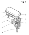
- the electrical setting device for headlamp positioning includes, as it is seen in the reference figures, a case (1) with a cover (2) where the electronic card (3) is housed, said electronic card (3) comprising a control chip (4) and a potentiometer (5), all components included in the card being soldered to said card upper side.
- the laminar section electronic card (3) has a square shape, having two square legs (12, 13) in one end (11), said legs having square notches (14), and the potentiometer (5) can be placed on either leg (12, 13).
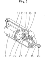
- the planet reduction gear (7) comprises a fixed crown (15) connected to the motor (6), which holds the radial turn crown (8); the inlet pinion (16) is centrally placed inside said assembly and has its outside end connected to the motor shaft (6), whereas its inside end is coupled, by means of a gear, to the satellite gears (17), having a double teeth (18, 19) with the largest diameter corresponding to the teeth (18) and smallest diameter corresponding to teeth (19), said satellite gears (17) transmitting the turning motion to the turning crown (8).
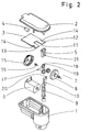
- the actuating stem (9) is defined by a cylinder shape body with ribs and a rack (10) fastened to its upper end, the rack being displaced from the stem axis with the flat surface of said reck upper end (10) provided with a leg (20) which holds the potentiometer (5) control lever (21).
- the electrical setting device for headlampo positioning can be made up by a cylinder shape case (22), having a diametral notch on its front end, which houses the device comprising an electronic card (23) designed to control a motor (6) with a shaft coupled to a speed reduction gear (7) with the associated shaft (24) acting, by means of a worm screw system, on the actuating stem (25).
- Said actuating stem (25) is defined by a cylinder body, with a hollow main portion and with a solid cylinder shape end portion of shorter diameter, having an spherical end (26) of slightly larger diameter, this end might be shaped as a ball joint or similar; the back end is provided with square profile (27), with a rim (28) split into two legs with a clip configuration, to hold the potentiometer (30) lever (29) and displace it accordingly; the said control lever (25) moves inside the neck (31) located in the case (22) front end.
Landscapes
- Engineering & Computer Science (AREA)
- Mechanical Engineering (AREA)
- Lighting Device Outwards From Vehicle And Optical Signal (AREA)
Claims (10)
- Appareil électrique de réglage du positionnement des phares du type de ceux utilisés pour ajuster la verticalité des phares à partir de la place du conducteur, comprenant un micro moteur électrique (6), un réducteur de vitesse (7), une tige faisant agir une parabole de phare (9 ; 25) et un potentiomètre (5 ; 30), où l'arbre de sortie du micro moteur (6) est associé à un réducteur de vitesse (7) lequel, par le biais d'un râtelier (10) et d'un système de pignons ou par le biais d'une vis sans fin, déplace la tige précitée (9 ; 25) de façon que le mouvement de rotation du moteur se transforme en un déplacement linéaire de la tige précitée (9 ; 25),
caractérisé en ce que
l'appareil électrique de réglage comprend un engrenage planétaire (7) en guise de réducteur de vitesse, ayant un arbre de rentrée sur le même axe que l'arbre de sortie, où une carte électronique de contrôle du mouvement (2 ; 23) se trouve dans le même râtelier (1 ; 25) que les autres composants et où la carte électronique de contrôle du mouvement (2 ; 23) comprend un potentiomètre (5 ; 30) pour fournir tension de rétroaction proportionnelle à la position des phares. - Un appareil électrique de réglage du positionnement des phares selon la revendication 1,
caractérisé en ce que
l'appareil électrique comprend un revêtement extérieur cylindrique (22) contenant les composants tels que le moteur (6), le mécanisme (7) et la carte électronique (23). - Un appareil électrique de réglage du positionnement des phares selon l'une des revendications précédentes,
caractérisé en ce que
le système de contrôle par carte électronique (23) est de forme carrée avec une encoche carrée à une extrémité formant un ensemble sur deux pieds (12, 13) qui rend possible de placer le potentiomètre (5) dans l'un ou l'autre pied, tous les éléments électroniques étant soudés sur la partie supérieure de la carte. - Un appareil électrique de réglage du positionnement des phares selon l'une des revendications précédentes,
caractérisé en ce que
l'engrenage planétaire comprend une couronne fixe (15) attachée au râtelier, associée à une couronne libre (8), de façon que la couronne libre (8) puisse tourner en fonction de la direction dans laquelle tourne le micro moteur (6) et en fonction de la partie centrale du réducteur (7) comprenant un pignon pour transmettre un mouvement circulaire aux trois mécanismes satellites (17) placés dans le réducteur, lequel, grâce à l'aide de la couronne fixe (15), permet à la couronne libre de tourner lentement. - Un appareil électrique de réglage du positionnement des phares selon l'une des revendications précédentes,
caractérisé en ce que
les trois mécanismes satellites (17) inclus dans le réducteur (7) ont deux séries de dents de différents diamètres sur leur périmètre. - Un appareil électrique de réglage du positionnement des phares selon l'une des revendications précédentes,
caractérisé en ce que
la branche (9) est composée d'un élément cylindrique avec de nombreuses stries et d'un râtelier (10) sur son extrémité supérieure, les dents se déplaçant sur l'axe de la branche alors que la partie inférieure de la branche comprend une borne sphérique ou un joint à rotule. - Un appareil électrique de réglage du positionnement des phares selon l'une des revendications précédentes,
caractérisé en ce que
le râtelier (10) associé à la branche (9) a un bord avec deux pieds situé à l'arrière de la partie supérieure, le levier du potentiomètre (5) étant placé entre les pieds précités. - Un appareil électrique de réglage du positionnement des phares selon l'une des revendications précédentes,
caractérisé en ce que
le réducteur de vitesse sous forme d'un engrenage planétaire (7) comprend un système de sortie (24) avec une vis sans fin qui en fait partie intégrante. - Un appareil électrique de réglage du positionnement des phares selon l'une des revendications précédentes,
caractérisé en ce que
le levier (25) comprend un cylindre creux dans sa partie principale, avec une vis sans fin, et se termine par une forme cylindrique de diamètre inférieur finissant en pointe, alors que l'autre extrémité est carrée se terminant en stries avec des pieds, le levier (29) du potentiomètre étant entre les pieds. - Un appareil électrique de réglage du positionnement des phares selon l'une des revendications précédentes,
caractérisé en ce que
la partie cylindrique (22) a un diamètre plus important sur une majeure partie que le diamètre de l'extrémité comprenant un collet pour guider la branche (25) dont le diamètre équivaut au diamètre extérieur de la branche.
Applications Claiming Priority (4)
| Application Number | Priority Date | Filing Date | Title |
|---|---|---|---|
| ES9701688 | 1997-07-30 | ||
| ES9701688A ES2131471B1 (es) | 1997-07-30 | 1997-07-30 | Corrector electrico de faro con desplazamiento lineal. |
| ES9701687 | 1997-07-30 | ||
| ES9701687A ES2131470B1 (es) | 1997-07-30 | 1997-07-30 | Corrector electrico de faro de accion angular. |
Publications (3)
| Publication Number | Publication Date |
|---|---|
| EP0894665A2 EP0894665A2 (fr) | 1999-02-03 |
| EP0894665A3 EP0894665A3 (fr) | 2000-07-12 |
| EP0894665B1 true EP0894665B1 (fr) | 2003-10-01 |
Family
ID=26155080
Family Applications (1)
| Application Number | Title | Priority Date | Filing Date |
|---|---|---|---|
| EP19980500184 Expired - Lifetime EP0894665B1 (fr) | 1997-07-30 | 1998-07-30 | Dispositif de correction électronique de la position d'un phare |
Country Status (2)
| Country | Link |
|---|---|
| EP (1) | EP0894665B1 (fr) |
| DE (1) | DE69818580T2 (fr) |
Families Citing this family (7)
| Publication number | Priority date | Publication date | Assignee | Title |
|---|---|---|---|---|
| JP3887526B2 (ja) * | 1999-09-30 | 2007-02-28 | 株式会社小糸製作所 | 車輌用前照灯のレベリング装置 |
| JP3928687B2 (ja) * | 1999-09-30 | 2007-06-13 | 株式会社小糸製作所 | 車輌用前照灯のレベリング装置 |
| FR2807982B1 (fr) * | 2000-04-19 | 2002-07-05 | Valeo Vision | Systeme d'eclairage pour projecteur de vehicule automobile |
| GB2367120B (en) * | 2000-09-25 | 2004-12-29 | Tyc Brother Ind Co Ltd | Apparatus for controlling movement of a lamp unit relative to an Automobile body |
| ES1048090Y (es) * | 2001-01-12 | 2001-11-01 | Vyr Valvuleria Y Riegos Por As | Cabezal basculante para aspersor maestro. |
| CN102661578A (zh) * | 2012-04-28 | 2012-09-12 | 奇瑞汽车股份有限公司 | 一种汽车前照灯的调光结构 |
| US9809150B2 (en) | 2015-10-28 | 2017-11-07 | GM Global Technology Operations LLC | Headlamp assembly |
Family Cites Families (2)
| Publication number | Priority date | Publication date | Assignee | Title |
|---|---|---|---|---|
| JPS6192942A (ja) * | 1985-08-28 | 1986-05-10 | Koito Mfg Co Ltd | ヘツドランプレベリング装置 |
| IT1237749B (it) * | 1989-12-29 | 1993-06-15 | Carello Spa | Proiettore orientabile per veicoli |
-
1998
- 1998-07-30 EP EP19980500184 patent/EP0894665B1/fr not_active Expired - Lifetime
- 1998-07-30 DE DE69818580T patent/DE69818580T2/de not_active Expired - Fee Related
Also Published As
| Publication number | Publication date |
|---|---|
| EP0894665A3 (fr) | 2000-07-12 |
| DE69818580D1 (de) | 2003-11-06 |
| EP0894665A2 (fr) | 1999-02-03 |
| DE69818580T2 (de) | 2004-08-05 |
Similar Documents
| Publication | Publication Date | Title |
|---|---|---|
| US4915493A (en) | Automotive rear view mirror assembly | |
| US6641292B2 (en) | Illumination axis adjusting apparatus for automotive headlamps | |
| US4930370A (en) | Mirror drive for automotive remote-controlled rear-view mirror assembly | |
| US5105342A (en) | Headlight for a motor vehicle having an adjustable motor-driven reflector | |
| AU727643B2 (en) | Electrically controlled clamping device for a system for adjusting the position of one member relative to another member | |
| EP0894665B1 (fr) | Dispositif de correction électronique de la position d'un phare | |
| US11509189B2 (en) | Rotary actuator | |
| JP2008546963A (ja) | 左右対称に配置された接続コネクタを備えた伝動機構・駆動機構ユニット | |
| FR2456026A1 (fr) | Mecanisme de direction assistee pour vehicules automobiles | |
| US6478436B1 (en) | Sensing mirror position in a powered mirror positioning system | |
| WO1998042990A1 (fr) | Borne avec dispositif de fixation pour cables de commande | |
| GB2089958A (en) | Electrical adjusting device for headlamps of motor vehicles | |
| JP2000503468A (ja) | 前照灯の照明幅を調節するための装置 | |
| US7441910B1 (en) | Vehicular pivot mirror | |
| EP0716954A2 (fr) | Dispositif de réglage de l'axe optique pour un phare | |
| US20060023326A1 (en) | Mirror device for vehicle | |
| EP0956998B1 (fr) | Dispositif d'ajustement de la position d'un phare de véhicule | |
| CN114423668A (zh) | 线控转向式转向装置 | |
| US20070173078A1 (en) | Volute Spring | |
| KR200203102Y1 (ko) | 차량용 파워 스티어링 기어박스 | |
| GB1593896A (en) | Speed control devices for motor vehicles | |
| JPS57186549A (en) | Rotary body with slidable rod | |
| ES2131470A1 (es) | Corrector electrico de faro de accion angular. | |
| KR100410740B1 (ko) | 차량용 헤드램프 레벨링 디바이스 액추에이터 | |
| ES1042144U (es) | Dispositivo de regulacion para un reflector de un faro de vehiculo automovil. |
Legal Events
| Date | Code | Title | Description |
|---|---|---|---|
| PUAI | Public reference made under article 153(3) epc to a published international application that has entered the european phase |
Free format text: ORIGINAL CODE: 0009012 |
|
| AK | Designated contracting states |
Kind code of ref document: A2 Designated state(s): CH DE FR LI |
|
| AX | Request for extension of the european patent |
Free format text: AL;LT;LV;MK;RO;SI |
|
| PUAL | Search report despatched |
Free format text: ORIGINAL CODE: 0009013 |
|
| AK | Designated contracting states |
Kind code of ref document: A3 Designated state(s): AT BE CH CY DE DK ES FI FR GB GR IE IT LI LU MC NL PT SE |
|
| AX | Request for extension of the european patent |
Free format text: AL;LT;LV;MK;RO;SI |
|
| 17P | Request for examination filed |
Effective date: 20010102 |
|
| AKX | Designation fees paid |
Free format text: CH DE FR LI |
|
| 17Q | First examination report despatched |
Effective date: 20010906 |
|
| GRAH | Despatch of communication of intention to grant a patent |
Free format text: ORIGINAL CODE: EPIDOS IGRA |
|
| GRAH | Despatch of communication of intention to grant a patent |
Free format text: ORIGINAL CODE: EPIDOS IGRA |
|
| GRAA | (expected) grant |
Free format text: ORIGINAL CODE: 0009210 |
|
| AK | Designated contracting states |
Kind code of ref document: B1 Designated state(s): CH DE FR LI |
|
| REG | Reference to a national code |
Ref country code: CH Ref legal event code: EP |
|
| REF | Corresponds to: |
Ref document number: 69818580 Country of ref document: DE Date of ref document: 20031106 Kind code of ref document: P |
|
| REG | Reference to a national code |
Ref country code: CH Ref legal event code: NV Representative=s name: PETER RUTZ |
|
| ET | Fr: translation filed | ||
| PLBE | No opposition filed within time limit |
Free format text: ORIGINAL CODE: 0009261 |
|
| STAA | Information on the status of an ep patent application or granted ep patent |
Free format text: STATUS: NO OPPOSITION FILED WITHIN TIME LIMIT |
|
| 26N | No opposition filed |
Effective date: 20040702 |
|
| PGFP | Annual fee paid to national office [announced via postgrant information from national office to epo] |
Ref country code: DE Payment date: 20050928 Year of fee payment: 8 |
|
| PGFP | Annual fee paid to national office [announced via postgrant information from national office to epo] |
Ref country code: CH Payment date: 20060707 Year of fee payment: 9 |
|
| PGFP | Annual fee paid to national office [announced via postgrant information from national office to epo] |
Ref country code: FR Payment date: 20060719 Year of fee payment: 9 |
|
| PG25 | Lapsed in a contracting state [announced via postgrant information from national office to epo] |
Ref country code: DE Free format text: LAPSE BECAUSE OF NON-PAYMENT OF DUE FEES Effective date: 20070201 |
|
| REG | Reference to a national code |
Ref country code: CH Ref legal event code: PL |
|
| PG25 | Lapsed in a contracting state [announced via postgrant information from national office to epo] |
Ref country code: LI Free format text: LAPSE BECAUSE OF NON-PAYMENT OF DUE FEES Effective date: 20070731 Ref country code: CH Free format text: LAPSE BECAUSE OF NON-PAYMENT OF DUE FEES Effective date: 20070731 |
|
| REG | Reference to a national code |
Ref country code: FR Ref legal event code: ST Effective date: 20080331 |
|
| PG25 | Lapsed in a contracting state [announced via postgrant information from national office to epo] |
Ref country code: FR Free format text: LAPSE BECAUSE OF NON-PAYMENT OF DUE FEES Effective date: 20070731 |