EP0894665B1 - Elektronische Korrigiervorrichtung der Neigung eines Scheinwerfers - Google Patents
Elektronische Korrigiervorrichtung der Neigung eines Scheinwerfers Download PDFInfo
- Publication number
- EP0894665B1 EP0894665B1 EP19980500184 EP98500184A EP0894665B1 EP 0894665 B1 EP0894665 B1 EP 0894665B1 EP 19980500184 EP19980500184 EP 19980500184 EP 98500184 A EP98500184 A EP 98500184A EP 0894665 B1 EP0894665 B1 EP 0894665B1
- Authority
- EP
- European Patent Office
- Prior art keywords
- setting device
- headlamp
- precedent
- electrical
- electrical setting
- Prior art date
- Legal status (The legal status is an assumption and is not a legal conclusion. Google has not performed a legal analysis and makes no representation as to the accuracy of the status listed.)
- Expired - Lifetime
Links
- 238000006073 displacement reaction Methods 0.000 claims description 3
- 239000007787 solid Substances 0.000 claims description 2
- 230000001419 dependent effect Effects 0.000 description 1
- 238000004519 manufacturing process Methods 0.000 description 1
- 239000000463 material Substances 0.000 description 1
Images
Classifications
-
- B—PERFORMING OPERATIONS; TRANSPORTING
- B60—VEHICLES IN GENERAL
- B60Q—ARRANGEMENT OF SIGNALLING OR LIGHTING DEVICES, THE MOUNTING OR SUPPORTING THEREOF OR CIRCUITS THEREFOR, FOR VEHICLES IN GENERAL
- B60Q1/00—Arrangement of optical signalling or lighting devices, the mounting or supporting thereof or circuits therefor
- B60Q1/02—Arrangement of optical signalling or lighting devices, the mounting or supporting thereof or circuits therefor the devices being primarily intended to illuminate the way ahead or to illuminate other areas of way or environments
- B60Q1/04—Arrangement of optical signalling or lighting devices, the mounting or supporting thereof or circuits therefor the devices being primarily intended to illuminate the way ahead or to illuminate other areas of way or environments the devices being headlights
- B60Q1/06—Arrangement of optical signalling or lighting devices, the mounting or supporting thereof or circuits therefor the devices being primarily intended to illuminate the way ahead or to illuminate other areas of way or environments the devices being headlights adjustable, e.g. remotely-controlled from inside vehicle
- B60Q1/076—Arrangement of optical signalling or lighting devices, the mounting or supporting thereof or circuits therefor the devices being primarily intended to illuminate the way ahead or to illuminate other areas of way or environments the devices being headlights adjustable, e.g. remotely-controlled from inside vehicle by electrical means including means to transmit the movements, e.g. shafts or joints
Definitions
- the present descriptive specification refers, as the title indicates, to an electrical setting device for headlamp positioning, of the type used in vehicles in order to place correctly the headlamps vertical position.
- EP 0 733 536 B1 discloses an electric power steering device for assisting the steering operation of an automobile.
- the headlamps not provided with an electrical setting device have the disadvantage of being frequently defocused for it is relatively complicated having to open the engine hood and adjust the setting screws.
- An electrical setting device for headlamp positioning comprising a motion control electronic card, an electrical micromotor, a planet gear and a headlamp parabole actuating stem, all housed in a proper case.
- the electronic card receives the feeding signal, ground and the reference voltage which starts the device. Said electronic card compares the inlet reference signal with the feed back voltage proportional to the headlamp position, by means of a potentiometer directly connected to it. Depending on both voltages, the card logic establishes if the device has to operate and whether it should raise or lower the headlamp.
- the electrical motor operates depending on the polarity supplied by the card, turning in the required direction.
- the device could be placed inside a turning cylindrical case, which contains the electronic card that controls the electrical motor motion, so that said electrical motor, through the associated speed reduction gear, displaces the actuating stem.
- the displacement of said actuating stem is obtained by means of a rack and pinion system; the said actuating stem is provided in its lower end with twin leg rim which holds the potentiometer lever.
- the present invention provides the essential advantage of having very reduced dimensions as compared with the known means, with a high reliability based on a very simple design.
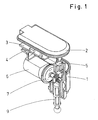
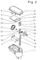
- the electrical setting device for headlamp positioning includes, as it is seen in the reference figures, a case (1) with a cover (2) where the electronic card (3) is housed, said electronic card (3) comprising a control chip (4) and a potentiometer (5), all components included in the card being soldered to said card upper side.
- the laminar section electronic card (3) has a square shape, having two square legs (12, 13) in one end (11), said legs having square notches (14), and the potentiometer (5) can be placed on either leg (12, 13).
- the planet reduction gear (7) comprises a fixed crown (15) connected to the motor (6), which holds the radial turn crown (8); the inlet pinion (16) is centrally placed inside said assembly and has its outside end connected to the motor shaft (6), whereas its inside end is coupled, by means of a gear, to the satellite gears (17), having a double teeth (18, 19) with the largest diameter corresponding to the teeth (18) and smallest diameter corresponding to teeth (19), said satellite gears (17) transmitting the turning motion to the turning crown (8).
- the actuating stem (9) is defined by a cylinder shape body with ribs and a rack (10) fastened to its upper end, the rack being displaced from the stem axis with the flat surface of said reck upper end (10) provided with a leg (20) which holds the potentiometer (5) control lever (21).
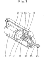
- the electrical setting device for headlampo positioning can be made up by a cylinder shape case (22), having a diametral notch on its front end, which houses the device comprising an electronic card (23) designed to control a motor (6) with a shaft coupled to a speed reduction gear (7) with the associated shaft (24) acting, by means of a worm screw system, on the actuating stem (25).
- Said actuating stem (25) is defined by a cylinder body, with a hollow main portion and with a solid cylinder shape end portion of shorter diameter, having an spherical end (26) of slightly larger diameter, this end might be shaped as a ball joint or similar; the back end is provided with square profile (27), with a rim (28) split into two legs with a clip configuration, to hold the potentiometer (30) lever (29) and displace it accordingly; the said control lever (25) moves inside the neck (31) located in the case (22) front end.
Landscapes
- Engineering & Computer Science (AREA)
- Mechanical Engineering (AREA)
- Lighting Device Outwards From Vehicle And Optical Signal (AREA)
Claims (10)
- Elektrische Einstellvorrichtung zum Positionieren von Scheinwerfern von der Art, die zum Einstellen der vertikalen Position von Fahrzeugscheinwerfern vom Fahrersitz aus verwendet wird, wobei diese einen elektrischen Mikromotor (6), ein Untersetzungsgetriebe (7), einen Parabolscheinwerfer Betätigungsstab (9; 25), und ein Potentiometer (5; 30) aufweist, wobei die Ausgangswelle des Mikromotors (6) mit einem Untersetzungsgetriebe (7) verbunden ist, welches über eine Zahnstange (10) und ein Ritzelsystem oder durch ein Schneckengetriebe den Betätigungsstab (9; 25) verschiebt, so dass die Motordrehbewegung in eine lineare Verschiebung des Betätigungsstabs (9; 25) umgewandelt wird,
dadurch gekennzeichnet, dass
die elektrische Einstellvorrichtung ein Planetengetriebe (7) als Untersetzungsgetriebe aufweist, wobei die Eingangswelle auf der gleichen Achse wie die Ausgangswelle liegt, und wobei ein elektronischer Schaltkreis (3; 23) zur Bewegungsregelung zusammen mit den anderen Komponenten im gleichen Gehäuse (1; 25) angeordnet ist, und wobei der elektronische Schaltkreis (3; 23) zur Bewegungsregelung ein Potentiometer (5; 30) zum zur Verfügung stellen einer Rückkopplungsspannung, die proportional zu der Scheinwerferposition ist, aufweist. - Elektrische Einstellvorrichtung zum Positionieren von Scheinwerfern gemäss Patentanspruch 1,
dadurch gekennzeichnet, dass
die elektrische Vorrichtung ein Gehäuse (22) mit zylindrischer Außenkontur aufweist, die die Komponenten, wie den Motor (6), das Getriebe (7) und den elektronischen Schaltkreis (23) aufnimmt. - Elektrische Einstellvorrichtung zum Positionieren von Scheinwerfern gemäss einem der voranstehenden Patentansprüche,
dadurch gekennzeichnet, dass
das Regelsystem des elektrischen Schaltkreises (3) eine quadratische Form mit quadratischen Nuten an einem Ende aufweist, die eine Anordnung mit zwei Beinen (12; 13) bilden, welche es ermöglicht, das Potentiometer (5) in irgendeinem der Beine anzuordnen, wobei alle elektronischen Komponenten auf der Oberseite des elektronischen Schaltkreises aufgelötet sind. - Elektrische Einstellvorrichtung zum Positionieren von Scheinwerfern gemäss einem der voranstehenden Patentansprüche,
dadurch gekennzeichnet, dass
das Planetenuntersetzungsgetriebe einen festen Zahnkranz (15) aufweist, der an dem Vorrichtungsgehäuse befestigt ist, der mit einem freien Zahnkranz (8) in Verbindung steht, so dass sich der freie Zahnkranz (8) gemäss der Drehrichtung des Mikromotors (6) drehen kann, wobei der zentrale Abschnitt des Untersetzungsgetriebes (7) ein Ritzel zum Übertragen einer kreisförmigen Umdrehung auf die drei Satelitenzahnräder (17) einschließt, die innerhalb des Untersetzungsgetriebes angeordnet sind, welches in Zusammenarbeit mit dem feststehenden Zahnkranz (15), eine langsame Umdrehung um den freien Zahnkranz ermöglicht. - Elektrische Einstellvorrichtung zum Positionieren von Scheinwerfern gemäss einem der voranstehenden Patentansprüche,
dadurch gekennzeichnet, dass
die drei Satelitenzahnräder (17), die in dem Untersetzungsgetriebe (7) enthalten sind, zwei Umfangsserien von Zähnen mit unterschiedlichem Durchmesser aufweisen. - Elektrische Einstellvorrichtung zum Positionieren von Scheinwerfern gemäss einem der voranstehenden Patentansprüche,
dadurch gekennzeichnet, dass
der Betätigungsstab (9) aus einem zylinderförmigen Körper mit mehreren Rippen zusammengesetzt ist, der eine Zahnstange (10) an seinem oberen Ende aufweist, wobei die Zahnstangenzähne von der Stabachse versetzt sind, während das untere Stabende mit einem sphärischen Anschluss oder Kugelgelenk vorgesehen ist. - Elektrische Einstellvorrichtung zum Positionierung von Scheinwerfern gemäss einem der voranstehenden Patentansprüche,
dadurch gekennzeichnet, dass
die Zahnstange (10), die mit dem Stab (9) im Zusammenhang steht, einen umgebogenen Rand mit zwei Beinen aufweist, der an der Rückseite des oberen Endes angeordnet ist, wobei der Hebel des Potentiometers (5) zwischen diesen Beinen gehalten ist. - Elektrische Einstellvorrichtung zum Positionieren von Scheinwerfern gemäss einem der voranstehenden Patentansprüche,
dadurch gekennzeichnet, dass
das Untersetzungsplanetengetriebe (7) eine Ausgangswelle (24) mit einer Schneckenschraube aufweist, die ein integraler Bestandteil derselben ist. - Elektrische Einstellvorrichtung zum Positionieren von Scheinwerfern gemäss einem der voranstehenden Patentansprüche,
dadurch gekennzeichnet, dass
der Betätigungshebel (25) aus einem Hohlzylinder hergestellt ist, der in seinem Hauptabschnitt innen eine Schneckenschraube aufweist, die einen festen zylinderförmigen Abschnitt mit geringeren Durchmesser aufweist, der in einer zugespitzten Form endet, wo gegen das entgegengesetzte Ende in einer viereckigen Form in einem Rand mit Beinen endet, wobei der Hebel (29) des Potentiometers (30) zwischen den Beinen gehalten wird. - Elektrische Einstellvorrichtung zum Positionieren von Scheinwerfern gemäss einem der voranstehenden Patentansprüche,
dadurch gekennzeichnet, dass
der zylinderförmige Körper (22) einen Hauptabschnitt mit einem Durchmesser größer als demjenigen eines Endabschnitts aufweist, der einen Hals aufweist, der den Betätigungsstab (25) um den äußeren Stabdurchmesser führt.
Applications Claiming Priority (4)
| Application Number | Priority Date | Filing Date | Title |
|---|---|---|---|
| ES9701687A ES2131470B1 (es) | 1997-07-30 | 1997-07-30 | Corrector electrico de faro de accion angular. |
| ES9701688 | 1997-07-30 | ||
| ES9701688A ES2131471B1 (es) | 1997-07-30 | 1997-07-30 | Corrector electrico de faro con desplazamiento lineal. |
| ES9701687 | 1997-07-30 |
Publications (3)
| Publication Number | Publication Date |
|---|---|
| EP0894665A2 EP0894665A2 (de) | 1999-02-03 |
| EP0894665A3 EP0894665A3 (de) | 2000-07-12 |
| EP0894665B1 true EP0894665B1 (de) | 2003-10-01 |
Family
ID=26155080
Family Applications (1)
| Application Number | Title | Priority Date | Filing Date |
|---|---|---|---|
| EP19980500184 Expired - Lifetime EP0894665B1 (de) | 1997-07-30 | 1998-07-30 | Elektronische Korrigiervorrichtung der Neigung eines Scheinwerfers |
Country Status (2)
| Country | Link |
|---|---|
| EP (1) | EP0894665B1 (de) |
| DE (1) | DE69818580T2 (de) |
Families Citing this family (7)
| Publication number | Priority date | Publication date | Assignee | Title |
|---|---|---|---|---|
| JP3928687B2 (ja) * | 1999-09-30 | 2007-06-13 | 株式会社小糸製作所 | 車輌用前照灯のレベリング装置 |
| JP3887526B2 (ja) * | 1999-09-30 | 2007-02-28 | 株式会社小糸製作所 | 車輌用前照灯のレベリング装置 |
| FR2807982B1 (fr) * | 2000-04-19 | 2002-07-05 | Valeo Vision | Systeme d'eclairage pour projecteur de vehicule automobile |
| GB2367120B (en) * | 2000-09-25 | 2004-12-29 | Tyc Brother Ind Co Ltd | Apparatus for controlling movement of a lamp unit relative to an Automobile body |
| ES1048090Y (es) * | 2001-01-12 | 2001-11-01 | Vyr Valvuleria Y Riegos Por As | Cabezal basculante para aspersor maestro. |
| CN102661578A (zh) * | 2012-04-28 | 2012-09-12 | 奇瑞汽车股份有限公司 | 一种汽车前照灯的调光结构 |
| US9809150B2 (en) | 2015-10-28 | 2017-11-07 | GM Global Technology Operations LLC | Headlamp assembly |
Family Cites Families (2)
| Publication number | Priority date | Publication date | Assignee | Title |
|---|---|---|---|---|
| JPS6192942A (ja) * | 1985-08-28 | 1986-05-10 | Koito Mfg Co Ltd | ヘツドランプレベリング装置 |
| IT1237749B (it) * | 1989-12-29 | 1993-06-15 | Carello Spa | Proiettore orientabile per veicoli |
-
1998
- 1998-07-30 EP EP19980500184 patent/EP0894665B1/de not_active Expired - Lifetime
- 1998-07-30 DE DE69818580T patent/DE69818580T2/de not_active Expired - Fee Related
Also Published As
| Publication number | Publication date |
|---|---|
| DE69818580T2 (de) | 2004-08-05 |
| DE69818580D1 (de) | 2003-11-06 |
| EP0894665A3 (de) | 2000-07-12 |
| EP0894665A2 (de) | 1999-02-03 |
Similar Documents
| Publication | Publication Date | Title |
|---|---|---|
| US4915493A (en) | Automotive rear view mirror assembly | |
| US6641292B2 (en) | Illumination axis adjusting apparatus for automotive headlamps | |
| US5105342A (en) | Headlight for a motor vehicle having an adjustable motor-driven reflector | |
| AU727643B2 (en) | Electrically controlled clamping device for a system for adjusting the position of one member relative to another member | |
| US11509189B2 (en) | Rotary actuator | |
| EP0894665B1 (de) | Elektronische Korrigiervorrichtung der Neigung eines Scheinwerfers | |
| JPS5937396Y2 (ja) | 自動車のアウタ−ミラ−の角度調整装置 | |
| KR19980701551A (ko) | 단일 피벗형 전동 접힘식 백미러(exterior mirror with single pivot power fold) | |
| FR2456026A1 (fr) | Mecanisme de direction assistee pour vehicules automobiles | |
| US20190264788A1 (en) | Electric actuator | |
| JPH0217371B2 (de) | ||
| US20020176181A1 (en) | Sensing mirror position in a powered mirror positioning system | |
| FR2815318B1 (fr) | Systeme et volant de direction pour vehicule | |
| GB2089958A (en) | Electrical adjusting device for headlamps of motor vehicles | |
| US7441910B1 (en) | Vehicular pivot mirror | |
| US3493295A (en) | Memory mirror | |
| KR960003459Y1 (ko) | 차량용 아웃사이드 백밀러(Out Side Back Mirror)의 경사각 조정장치 | |
| EP0716954A2 (de) | Vorrichtung zum Einstellen der optischen Achse eines Scheinwerfers | |
| US20070173078A1 (en) | Volute Spring | |
| KR200203102Y1 (ko) | 차량용 파워 스티어링 기어박스 | |
| US6871529B2 (en) | Throttle valve adjustment unit | |
| JPS62110457A (ja) | 2つの部材を同時に駆動するための減速装置 | |
| GB1593896A (en) | Speed control devices for motor vehicles | |
| JPS57186549A (en) | Rotary body with slidable rod | |
| ES2131470A1 (es) | Corrector electrico de faro de accion angular. |
Legal Events
| Date | Code | Title | Description |
|---|---|---|---|
| PUAI | Public reference made under article 153(3) epc to a published international application that has entered the european phase |
Free format text: ORIGINAL CODE: 0009012 |
|
| AK | Designated contracting states |
Kind code of ref document: A2 Designated state(s): CH DE FR LI |
|
| AX | Request for extension of the european patent |
Free format text: AL;LT;LV;MK;RO;SI |
|
| PUAL | Search report despatched |
Free format text: ORIGINAL CODE: 0009013 |
|
| AK | Designated contracting states |
Kind code of ref document: A3 Designated state(s): AT BE CH CY DE DK ES FI FR GB GR IE IT LI LU MC NL PT SE |
|
| AX | Request for extension of the european patent |
Free format text: AL;LT;LV;MK;RO;SI |
|
| 17P | Request for examination filed |
Effective date: 20010102 |
|
| AKX | Designation fees paid |
Free format text: CH DE FR LI |
|
| 17Q | First examination report despatched |
Effective date: 20010906 |
|
| GRAH | Despatch of communication of intention to grant a patent |
Free format text: ORIGINAL CODE: EPIDOS IGRA |
|
| GRAH | Despatch of communication of intention to grant a patent |
Free format text: ORIGINAL CODE: EPIDOS IGRA |
|
| GRAA | (expected) grant |
Free format text: ORIGINAL CODE: 0009210 |
|
| AK | Designated contracting states |
Kind code of ref document: B1 Designated state(s): CH DE FR LI |
|
| REG | Reference to a national code |
Ref country code: CH Ref legal event code: EP |
|
| REF | Corresponds to: |
Ref document number: 69818580 Country of ref document: DE Date of ref document: 20031106 Kind code of ref document: P |
|
| REG | Reference to a national code |
Ref country code: CH Ref legal event code: NV Representative=s name: PETER RUTZ |
|
| ET | Fr: translation filed | ||
| PLBE | No opposition filed within time limit |
Free format text: ORIGINAL CODE: 0009261 |
|
| STAA | Information on the status of an ep patent application or granted ep patent |
Free format text: STATUS: NO OPPOSITION FILED WITHIN TIME LIMIT |
|
| 26N | No opposition filed |
Effective date: 20040702 |
|
| PGFP | Annual fee paid to national office [announced via postgrant information from national office to epo] |
Ref country code: DE Payment date: 20050928 Year of fee payment: 8 |
|
| PGFP | Annual fee paid to national office [announced via postgrant information from national office to epo] |
Ref country code: CH Payment date: 20060707 Year of fee payment: 9 |
|
| PGFP | Annual fee paid to national office [announced via postgrant information from national office to epo] |
Ref country code: FR Payment date: 20060719 Year of fee payment: 9 |
|
| PG25 | Lapsed in a contracting state [announced via postgrant information from national office to epo] |
Ref country code: DE Free format text: LAPSE BECAUSE OF NON-PAYMENT OF DUE FEES Effective date: 20070201 |
|
| REG | Reference to a national code |
Ref country code: CH Ref legal event code: PL |
|
| PG25 | Lapsed in a contracting state [announced via postgrant information from national office to epo] |
Ref country code: LI Free format text: LAPSE BECAUSE OF NON-PAYMENT OF DUE FEES Effective date: 20070731 Ref country code: CH Free format text: LAPSE BECAUSE OF NON-PAYMENT OF DUE FEES Effective date: 20070731 |
|
| REG | Reference to a national code |
Ref country code: FR Ref legal event code: ST Effective date: 20080331 |
|
| PG25 | Lapsed in a contracting state [announced via postgrant information from national office to epo] |
Ref country code: FR Free format text: LAPSE BECAUSE OF NON-PAYMENT OF DUE FEES Effective date: 20070731 |