EP0893676A2 - Combined pressure responsive transducer and temperature sensor apparatus - Google Patents
Combined pressure responsive transducer and temperature sensor apparatus Download PDFInfo
- Publication number
- EP0893676A2 EP0893676A2 EP98305857A EP98305857A EP0893676A2 EP 0893676 A2 EP0893676 A2 EP 0893676A2 EP 98305857 A EP98305857 A EP 98305857A EP 98305857 A EP98305857 A EP 98305857A EP 0893676 A2 EP0893676 A2 EP 0893676A2
- Authority
- EP
- European Patent Office
- Prior art keywords
- diaphragm
- substrate
- electric
- connection pads
- fluid pressure
- Prior art date
- Legal status (The legal status is an assumption and is not a legal conclusion. Google has not performed a legal analysis and makes no representation as to the accuracy of the status listed.)
- Granted
Links
Images

Classifications
-
- G—PHYSICS
- G01—MEASURING; TESTING
- G01L—MEASURING FORCE, STRESS, TORQUE, WORK, MECHANICAL POWER, MECHANICAL EFFICIENCY, OR FLUID PRESSURE
- G01L19/00—Details of, or accessories for, apparatus for measuring steady or quasi-steady pressure of a fluent medium insofar as such details or accessories are not special to particular types of pressure gauges
- G01L19/0092—Pressure sensor associated with other sensors, e.g. for measuring acceleration or temperature
-
- G—PHYSICS
- G01—MEASURING; TESTING
- G01L—MEASURING FORCE, STRESS, TORQUE, WORK, MECHANICAL POWER, MECHANICAL EFFICIENCY, OR FLUID PRESSURE
- G01L9/00—Measuring steady of quasi-steady pressure of fluid or fluent solid material by electric or magnetic pressure-sensitive elements; Transmitting or indicating the displacement of mechanical pressure-sensitive elements, used to measure the steady or quasi-steady pressure of a fluid or fluent solid material, by electric or magnetic means
- G01L9/0041—Transmitting or indicating the displacement of flexible diaphragms
- G01L9/0072—Transmitting or indicating the displacement of flexible diaphragms using variations in capacitance
- G01L9/0075—Transmitting or indicating the displacement of flexible diaphragms using variations in capacitance using a ceramic diaphragm, e.g. alumina, fused quartz, glass
Definitions
- This application relates generally to condition responsive sensors and more particularly to combined fluid pressure and temperature sensor apparatus.
- Fluid pressure responsive capacitive transducers comprising a variable capacitor mounted in a fluid chamber having a thin ceramic diaphragm exposed to the fluid so that changes in fluid pressure cause concomitant changes in the position of the diaphragm to thereby cause a change in the capacitance of the capacitor are well known in the art. Transducers of this type are shown and described, for example, in U.S. Patent No. 4,716,492, the subject matter of which is incorporated herein by this reference. In that patent, a thin ceramic diaphragm is shown mounted in closely spaced. sealed, overlying relation to a ceramic substrate.
- Capacitor terminal pins having one end connected to the capacitor plates are mounted in bores extending through the substrate with an opposite end connected to signal conditioning circuitry disposed in an electric circuit chamber at an opposite surface of the substrate.
- a connector body of electrical insulating material received over the signal conditioning circuitry, mounts transducer terminals extending into the electric circuit chamber for connection to the signal conditioning circuitry. Capacitance is converted by the circuitry to an output voltage related to the fluid pressure.
- the capacitor is received in a suitable housing having a fluid receiving port and is provided with a fluid seal enabling the transducer to be used with fluid pressures up to 10,000 psi or higher.
- a combined pressure responsive transducer and temperature sensor comprise a housing having a fluid pressure receiving port in fluid communication with a fluid pressure chamber.
- a variable capacitor having a rigid substrate and a flexible diaphragm are each provided with a capacitor plate on a respective face surface with the diaphragm attached to and spaced from the substrate and with the capacitor plates facing one another in aligned spaced apart relation in a gap formed by a generally annular glass seal.
- the variable capacitor is disposed in the housing with the diaphragm exposed to the fluid pressure chamber. Electrical traces extend from the capacitor plates into an enclosed window or opening in the glass seal for electrical connection with electrical pins extending through the substrate.
- the opposite ends of the electrical pins are connected to signal conditioning circuitry disposed in an electric circuit chamber formed between the substrate and an electrical connector body which mounts transducer terminals also connected to the signal conditioning circuitry.
- a temperature responsive element is mounted preferably for direct engagement with the fluid being monitored and is provided with electrical leads which extend through an opening in the diaphragm near its outer periphery aligned with the glass seal.
- the electrical leads are connected to first connection pads in enclosed windows in the glass seal which in turn have traces extending through the glass seal to respective second connection pads in other enclosed windows in the glass seal thereby forming a hermetic seal between the first and second connection pads.
- Temperature sensor electric pins connectable to the signal conditioning circuitry, extend through the substrate and are electrically connected to the respective second connection pads.
- the temperature responsive element e.g., a resistive element
- the temperature responsive element comprises a pill type of thermistor with wire leads connected to spaced apart portions of the thermistor with the leads extending through respective openings in the diaphragm at a location aligned with enclosed windows of the seal and preferably into closed ended bores in the substrate to provide mechanical support for the leads.
- the thermistor may be disposed within the port of the housing or it may extend beyond the port with or without a protective sheath.
- the thermistor leads may also be bent so that the thermistor is placed within the fluid chamber closely adjacent to the diaphragm.
- the sensor is mounted on a heat conductive probe which extends beyond the location of the sensor into the fluid medium.
- the thermistor either thick film or surface mount type, may be mounted directly on the substrate through an opening in the diaphragm within a closed opening of the seal, i.e., closed in directions along a transversely extending plane but open in a direction perpendicular to the plane.
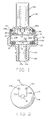
- the temperature sensor is shown combined with a monolithic variable capacitor.
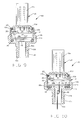
- a combined pressure and temperature sensor device 10 made in accordance with the invention comprises a housing 12 formed of suitable metallic material, such as zinc coated steel, having a first end 12a formed with a fluid receiving port 12b.
- a threaded portion 12c is provided for coupling in a fluid pressure line to be monitored (not shown).
- An annular groove 12d is formed adjacent to the threaded portion for reception of a suitable o-ring seal (not shown) or the like.
- Sidewall 12g may be formed with a hexagonal outer configuration to facilitate installation and removal of the housing from a fluid medium coupling.
- a fluid pressure chamber 12e is formed in housing 12 in fluid communication with port 12b.
- a variable capacitor 14 having a substrate portion 14a and a flexible diaphragm portion 14b attached to the substrate in spaced apart sealed relation, is received in chamber 12e with diaphragm portion 14b exposed to the fluid pressure chamber.
- a suitable gasket 16 is placed between capacitor 14 and the bottom wall 12f of chamber 12e to provide a fluid seal.
- An electrically insulative connector 20 has an end 20a received in the open end formed by sidewall 12g. End 20a is formed with a radially extending circumferential flange 20b so that attenuated distal end wall portion 12h of the housing can be deformed inwardly to clampingly engage the connector. Preferably, a suitable gasket 22 is placed between distal end wall portion 12h and the connector for providing an environmental seal.
- Connector 20 mounts, as by insert molding, a plurality of connector terminals 24 which extend from a location within a shroud 20c into a recessed electric circuit chamber 20d for electrical connection with signal conditioning circuit 26.
- Signal conditioning circuitry of the type used is disclosed in U.S. Patent No. 4,982,351, the subject matter of which is incorporated herein by this reference, and to which reference may be had for description of the operation of the circuitry.
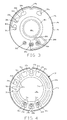
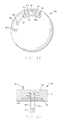
- substrate 14a is a generally circular, rigid, disc shaped member formed of suitable electrically insulative material, such as ceramic, having opposed planar face surfaces 14c, 14d.
- a stationary capacitor plate 28a of suitable electrically conductive material is centrally disposed on face surface 14c with a conductive trace 28b extending radially outwardly to an electric pin 30a.
- a conventional guard ring 28c of electrically conductive material is also disposed on face surface 14c essentially surrounding plate 28a with an electrically conductive trace 28d connecting the ring to an electric pin 30b.
- Pins 30a, 30b, along with pin 30c to be discussed below, are mounted in bores provided through substrate 14a and are electrically connected to respective electrically conductive traces by means of conductive epoxy or the like, in a known manner.
- Two additional electric pins 30d, 30e extend through bores in substrate 14a and are electrically connected by means of conductive epoxy or the like to respective connector pads 32c, 32d, which in turn are connected respectively to conductive traces 32e, 32f, and they in turn are respectively connected to connection pads 32g, 32h.
- Pins 30d, 30e are aligned respectively with enclosed windows 34g, 34h and connection pads 32g and 32h are respectively aligned with windows 34k, 34j.
- Flexible diaphragm 14b, Fig. 6, also a generally circular member preferably formed of the same material as substrate 14a and having a matching outer periphery, has opposed planar face surfaces 14e, 14f with an electrically conductive capacitive plate 28e centrally disposed on face surface 14e and connected with electrically conductive joiner pad 28f through trace 28g.
- pad 28f will be in alignment with pin 30c for electrical connection using conductive epoxy or the like.
- First and second apertures 14j, 14k are formed through diaphragm 14b adjacent to the outer periphery at a location which corresponds to the windows 34k, 34j, respectively of the glass sealing and securing means 34 to be discussed.
- inner and outer ring portions 34a, 34b, of the glass seal pattern circumscribe the substrate on face 14c and are connected by generally radially extending fingers 34c forming a plurality of enclosed windows within the glass pattern including windows 34d, 34e, 34f, 34g, 34h, 34j and 34k.
- a temperature responsive resistive element for example, a thick film layer 32 of suitable material such as platinum is disposed on face 14f of diaphragm 14b and is provided with electrically conductive traces 32a, 32b respectively, connected to spaced apart portions of layer 32 which extend to apertures 14k, 14j, respectively.
- Traces 32a, 32b are electrically connected to connection pads 32h, 32g respectively, as by use of conductive epoxy, via fill or pins, to complete an electrical path between electric pins 30d, 30e through traces 32e, 32f, 32a, 32b and thermistor film 32.
- Traces 32e, 32f each extend from one glass enclosed window through a glass seal to another glass enclosed window.
- the windows aligned with apertures 14j, 14k are exposed to the fluid medium being monitored and are hermetically sealed from the windows aligned with pins 30d, 30e which extend into the electric circuit chamber.
- the signal conditioning circuitry 26 conditions the electric signal from the thermistor to provide an output in a known manner.
- a device made in accordance with Figs. 1-6 combines a temperature sensing function having an effective glass seal for the temperature sensing element with a pressure sensing function which does not affect the pressure sensing function and which can be used with fluid pressures ranging from a few psi up to 4000 psi or higher.
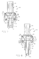
- a combined pressure and temperature sensing device 40 in which the temperature sensing element is a disc shaped resistive thermistor element 42 with wire leads 42a, 42b attached to opposite face surfaces of element 42.
- the opposite ends 42c, 42d respectively, of wire leads 42a, 42b are received through apertures 14j, 14k of diaphragm 14b and preferably into closed ended bores 14m. 14n respectively of substrate 14a to provide mechanical support for the wire leads.
- Electrical connection to connection pads 32g, 32h is effected by means of conductive epoxy or the like.
- thermistor element 42 is completely surrounded by the fluid medium while still being protected from potential damage caused by handling during assembly, shipping or installing.
- Fig. 8 illustrates another embodiment in which the combined sensor device 50 is provided with a tubular guard 52 having a flange 52a received in fluid pressure chamber 12e and a castellated open end 52b.
- An annular land 52c provides a stop surface for capacitor 14 and defines the effective space for fluid chamber 12e.
- Suitable gasket 16' is received between flange 52a and the sidewall of housing 12.
- Thermistor element 42 is disposed at the castellated end 52b for placement directly in a conduit or the like containing the fluid medium being monitored.
- Thermistor element 42 is the same as in the Fig. 7 embodiment and wire leads 42a', 42b' correspond to wire leads 42a, 42b except that they are extended in length.
- Fig. 9 illustrates another alternative embodiment in which the combined sensor device 60 includes wire leads 42a", 42b", corresponding to leads 42a, 42b of Fig. 7 but shortened, which are attached to thermistor element 42 and bent approximately 90 degrees so that thermistor element 42 is disposed closely adjacent diaphragm 14b.
- Fig. 10 illustrates an alternative embodiment in which the combined sensor device 70 comprises a thermistor element 42 thermally coupled with a heat conductive probe member 72 which extends beyond thermistor element 42 a selected distance, for example, as shown in the drawing beyond end 12a into the fluid medium.
- Probe member 72 is electrically attached to thermistor element 42 with a separate lead 74 or the like electrically attached to a spaced apart portion of the thermistor element 42.
- Lead 74 and probe member 72 are respectively attached to connection pads 32g, 32h in the same manner as in the Figs. 7-9 embodiments.
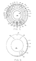
- a combined sensor 80 is shown without the housing and connector for simplicity of illustration.
- an aperture 14p is formed in the diaphragm 14 extending between connection pads 32h, 32g and thermistor element 82, either a surface mount element or a filmed element is placed directly on face 14c of substrate 14a.
- Electric traces 82a, 82b electrically connect spaced apart portions of thermistor element 82 with connection pads 32g, 32h, respectively.
- a combined sensor 90 also shown without the housing and connector for purposes of illustration, comprises a monolithic body 14' of suitable material, such as ceramic, having a cavity 14p formed between a substrate portion 14a' and a diaphragm portion 14b'.
- Monolithic body 14' can be formed, for example, by taking powdered ceramic material coated with an organic binder and pressed into substrate portion 14a' with a recess 14p and a diaphragm portion 14b' as shown in Fig. 13.
- a fugitive spacer element 92 of decomposable material may be placed in recess 14p to maintain the selected configuration of the recess.
- Metallized coatings such as the patterns of Figs.
- a pressure responsive variable capacitor is disclosed as a specific condition responsive sensor combined with the temperature sensor, it will be understood that the temperature sensor can be combined with other condition responsive sensors having a diaphragm attached to a substrate by means of an annular seal or margin such as, for example, a pressure responsive strain resistive sensor or an acceleration sensor where the leads of the temperature sensor extend through the annular seal or margin as shown and described herein.
- glass is a preferred sealant and spacing material, other suitable sealing and spacing materials may be used, if desired.
- the thermistor and leads can be coated with a layer of electrically insulative material thick enough to provide electrical insulation but thin enough to avoid significantly affecting the thermal coupling between the fluid and the sensor.
Abstract
Description
Claims (22)
- Combined fluid pressure and temperature sensor apparatus comprisinga housing having first and second ends, a fluid pressure receiving port disposed at the first end, a fluid pressure receiving chamber formed in the housing with the port in fluid receiving communication therewith, a tubular wall formed at the second end of the housing forming an open end,a variable capacitor having a rigid electrically insulative substrate and opposing first and second relatively planar face surfaces and a generally circular outer periphery, a relatively flexible diaphragm formed of electrically insulative material having opposed first and second generally planar face surfaces and a generally circular outer periphery matching that of the substrate periphery, a capacitor plate disposed on the first face surface of each of the substrate and the diaphragm, the diaphragm disposed on the substrate with a generally annular glass seal therebetween disposed adjacent the peripheries of the substrate and the diaphragm, the capacitor plates being aligned and facing each other and being spaced apart by the glass seal to form a gap, the variable capacitor disposed in the housing with the second face surface of the diaphragm exposed to the fluid pressure receiving chamber,an electrically insulative connector body received in the open end of the housing, an electric circuit chamber formed between the connector body and the variable capacitor, a signal conditioning electric circuit received in the electric circuit chamber, electric terminals mounted in the connector body extending into the electric circuit chamber and being connected to the signal conditioning electric circuit, electric pins extending through the substrate aligned with the glass seal and having one end connected to the signal conditioning electric circuit, the other end of at least some electric pins electrically connected to the capacitor plates.a temperature responsive element, first and second electric leads electrically attached to spaced portions of the resistive element, the leads extending from a location external of the capacitor and being electrically connected to two other of the electric pins extending through the substrate.
- Combined fluid pressure and temperature sensor apparatus according to claim 1 in which the temperature responsive element is disposed on the second face surface of the diaphragm and the electric leads include coated traces on the second face surface of the diaphragm.
- Combined fluid pressure and temperature sensor apparatus according to claim 1 in which the electric leads comprise wire elements and the temperature responsive element is disposed in the port of the housing.
- Combined fluid pressure and temperature sensor apparatus according to claim 1 in which the electric leads comprise wire elements and the temperature responsive element is disposed externally of the housing.
- Combined fluid pressure and temperature sensor apparatus according to claim 1 in which the electric leads comprise elements bent approximately ninety degrees so that the temperature responsive element is disposed adjacent the second face surface of the diaphragm.
- Combined fluid pressure and temperature sensor apparatus according to claim 1 further comprising an elongated heat conductive probe member having first and second opposite ends, the first end mounted in the substrate with the probe member extending through the diaphragm, the temperature responsive element mounted on the probe member.
- Combined fluid pressure and temperature sensor apparatus according to claim 6 in which the temperature responsive element is mounted proximate to the second face surface on the diaphragm and the probe member extends beyond the temperature responsive element.
- Combined fluid pressure and temperature sensor apparatus according to claim 1 in which first connection pads of electrically conductive material are disposed on the first face surface of the substrate within the glass seal and aligned with an aperture through the diaphragm, two electrically conductive second connection pads are disposed on the first face surface of the substrate spaced from the first connection pads, each second connection pad electrically connected to a respective first connection pad through the glass seal forming an hermetic seal between the first and second connection pads, the electric leads of the temperature responsive element being electrically connected to respective first connection pads and the second connection pads being electrically connected to respective electric pins extending through the substrate.
- Combined fluid pressure and temperature sensor apparatus according to claim 8 in which the second connection pads are electrically connected to respective electric pins through electrically conductive epoxy.
- Combined fluid pressure and temperature sensor apparatus according to claim 1 in which an aperture is formed in the diaphragm aligned with the annular glass seal and the temperature responsive element is mounted on the first face surface of the substrate.
- Combined first and second condition responsive sensor apparatus comprising a first condition responsive sensor having a rigid electrically insulative substrate, a relatively flexible diaphragm formed of electrically insulative material, the diaphragm disposed on the substrate with a generally annular seal therebetween, electric pins extending through the substrate, at least some of the electric pins connected to the first condition responsive sensor,
the second condition responsive sensor comprising a temperature responsive resistive element, first and second electric leads electrically attached to spaced portions of the resistive element, the leads extending from a location externally of the first condition responsive sensor through the diaphragm, two first connection pads of electrically conductive material disposed on a face surface of the substrate within the seal and aligned with an aperture through the diaphragm, two electrically conductive second connection pads disposed on the face surface of the substrate spaced from the first connection pads, each second connection pad electrically connected to a respective first connection pad through the seal forming a seal between the first and second connection pads, the electric leads of the temperature responsive resistive element being electrically connected to respective first connection pads and the second connection pads electrically connected to other respective electric pins extending through the substrate. - Combined first and second condition responsive sensor apparatus according to claim 11 in which the first condition responsive sensor comprises a pressure responsive variable capacitor.
- Combined pressure responsive transducer and temperature sensor comprisinga housing having first and second ends, a fluid pressure receiving port disposed at the first end, a fluid pressure receiving chamber formed in the housing with the port in fluid receiving communication therewith, a tubular wall formed at the second end of the housing forming an open end,a pressure sensor having a generally circular outer periphery the pressure sensor having a substrate and, a relatively flexible diaphragm formed of electrically insulative material, the diaphragm disposed on the substrate with a generally annular glass seal therebetween disposed adjacent the peripheries of the substrate and the diaphragm, the pressure sensor disposed in the housing with a face surface of the diaphragm exposed to the fluid pressure receiving chamber,an electrically insulative connector body received in the open end of the housing, an electric circuit chamber formed between the connector body and the substrate, a signal conditioning electric circuit received in the electric circuit chamber, electric terminals mounted in the connector body extending into the electric circuit chamber and being connected to the signal conditioning electric circuit, electric pins extending through the substrate aligned with the glass seal and having one end connected to the signal conditioning electric circuit, the other end of at least some electric pins electrically connected to the pressure sensor,a temperature responsive element, first and second electric leads electrically attached to spaced portions of the resistive element, the leads extending from a location external of the pressure sensor through the diaphragm and being electrically connected to other respective electric pins extending through the substrate.
- Combined fluid pressure and temperature sensor apparatus according to claim 13 in which the temperature responsive element is disposed on the face surface of the diaphragm and the electric leads include coated traces on the face surface of the diaphragm.
- Combined fluid pressure and temperature sensor apparatus according to claim 13 in which the electric leads comprise elements received in closed ended bores formed in the substrate.
- Combined fluid pressure and temperature sensor apparatus according to claim 13 in which the electric leads comprise wire elements bent approximately 90 degrees so that the temperature responsive element is disposed adjacent the face surface of the diaphragm.
- Combined fluid pressure and temperature sensor apparatus according to claim 13 further comprising an elongated heat conductive probe member having first and second opposite ends, the first end mounted in the substrate with the probe member extending through the diaphragm, the temperature responsive element mounted on the probe member.
- Combined fluid pressure responsive transducer and temperature sensor apparatus according to claim 17 in which the temperature responsive element is mounted proximate to the face surface on the diaphragm and the probe member extends beyond the temperature responsive element.
- A combined fluid pressure responsive transducer and temperature sensor apparatus according to claim 13 in which two first connection pads of electrically conductive material are disposed on a face surface of the substrate within the glass seal and aligned with an aperture through the diaphragm, two electrically conductive second connection pads are disposed on the face surface of the substrate spaced from the first connection pads, each second connection pad electrically connected to a respective first connection pad through the glass seal forming an hermetic seal between the first and second connection pads, the electric leads of the temperature responsive element being formed of wire elements electrically connected to respective first connection pads and the second connection pads electrically connected to respective electric pins extending through the substrate.
- Combined pressure and temperature sensor apparatus according to claim 19 in which the electric leads comprise wire elements soldered to the first connection pads.
- Combined fluid pressure and temperature sensor apparatus according to claim 19 in which an aperture is formed in the diaphragm aligned with the annular glass seal and the temperature resistive element is mounted on the face surface of the substrate.
- Combined first and second condition responsive sensor apparatus comprising a first condition responsive sensor having a body of ceramic material having an outer periphery and a top and a bottom face surface and having a closed cavity in the body adjacent to and separated from the bottom face surface by a relatively flexible diaphragm, electric pins extending through the top surface into the body, at least some of the electric pins aligned with an annular margin between the cavity and the outer periphery, at least some of the electric pins connected to the first condition responsive sensor,
the second condition responsive sensor comprising a temperature responsive resistive element, first and second electric leads electrically attached to spaced portions of the resistive element, the leads extending from a location externally of the first condition responsive sensor through the bottom face surface aligned with the margin, two first connection pads electrically conductive material disposed within the body and within the margin and aligned with an aperture extending through the bottom face surface, two electrically conductive second connection pads disposed within the body spaced from the first connection pads, each second connection pad electrically connected to a respective first connected pad, the electric leads of the temperature responsive resistive element being electrically connected to respective first connection pads and the second connection pads electrically connected to other respective electric pins extending through the top face surface.
Applications Claiming Priority (2)
| Application Number | Priority Date | Filing Date | Title |
|---|---|---|---|
| US5367497P | 1997-07-24 | 1997-07-24 | |
| US53674P | 1997-07-24 |
Publications (3)
| Publication Number | Publication Date |
|---|---|
| EP0893676A2 true EP0893676A2 (en) | 1999-01-27 |
| EP0893676A3 EP0893676A3 (en) | 1999-12-15 |
| EP0893676B1 EP0893676B1 (en) | 2003-10-08 |
Family
ID=21985806
Family Applications (1)
| Application Number | Title | Priority Date | Filing Date |
|---|---|---|---|
| EP98305857A Expired - Lifetime EP0893676B1 (en) | 1997-07-24 | 1998-07-22 | Combined pressure responsive transducer and temperature sensor apparatus |
Country Status (4)
| Country | Link |
|---|---|
| US (1) | US5974893A (en) |
| EP (1) | EP0893676B1 (en) |
| JP (1) | JP4208295B2 (en) |
| DE (1) | DE69818762T2 (en) |
Cited By (19)
| Publication number | Priority date | Publication date | Assignee | Title |
|---|---|---|---|---|
| EP1096241A1 (en) * | 1999-11-01 | 2001-05-02 | Delphi Technologies, Inc. | Integrated pressure and temperature sensor for high pressure fluid |
| EP1203937A1 (en) * | 2000-11-06 | 2002-05-08 | Skg Italiana Spa | Sensor unit |
| WO2003029656A1 (en) * | 2001-10-03 | 2003-04-10 | Davey Products Pty Ltd | Pump control system |
| FR2846416A1 (en) * | 2002-10-23 | 2004-04-30 | Denso Corp | Combined pressure and temperature sensor e.g. for vehicle engine has pressure detector and temperature probe fixed to conductor wire |
| AU2002333031B2 (en) * | 2001-10-03 | 2007-05-17 | Davey Products Pty Ltd | Pump control system |
| WO2008031691A1 (en) * | 2006-09-15 | 2008-03-20 | Robert Bosch Gmbh | Sensor plug for combined pressure- and temperature measurement |
| US7467891B2 (en) | 2005-11-29 | 2008-12-23 | Sensata Technologies, Inc. | Sensor arrangement for measuring a pressure and a temperature in a fluid |
| DE102007042789A1 (en) | 2007-09-07 | 2009-03-12 | Robert Bosch Gmbh | Plug-in sensor for measuring at least one property of a fluid medium |
| DE102008002499A1 (en) | 2008-06-18 | 2009-12-24 | Robert Bosch Gmbh | Measuring sensor for combined pressure and temperature measurement of e.g. gas, in common-rail-system in automobile, has optical pressure sensor producing optical pressure signal corresponding to pressure of fluid medium |
| EP2333508A1 (en) * | 2009-12-11 | 2011-06-15 | Armaturenbau GmbH | Pressure transmitter with temperature sensor |
| ITTO20100490A1 (en) * | 2010-06-10 | 2011-12-11 | Bitron Spa | INTEGRATED DEVICE FOR DETECTION OF THE PRESSURE AND TEMPERATURE OF A FUEL FLOW. |
| WO2012071693A1 (en) * | 2010-11-29 | 2012-06-07 | Wu Maoting | Pressure and temperature measuring device |
| CN103644936A (en) * | 2013-11-22 | 2014-03-19 | 北京宇航系统工程研究所 | A measurement apparatus used for a low temperature pressure accumulator |
| US20140150540A1 (en) * | 2012-11-30 | 2014-06-05 | Joris Robert Jan Lenferink | Method of integrating a temperature sensing element |
| US10345156B2 (en) | 2015-07-01 | 2019-07-09 | Sensata Technologies, Inc. | Temperature sensor and method for the production of a temperature sensor |
| US10428716B2 (en) | 2016-12-20 | 2019-10-01 | Sensata Technologies, Inc. | High-temperature exhaust sensor |
| US10502641B2 (en) | 2017-05-18 | 2019-12-10 | Sensata Technologies, Inc. | Floating conductor housing |
| US11346698B2 (en) * | 2019-06-21 | 2022-05-31 | Sporian Microsystems, Inc. | Compact pressure and flow sensors for very high temperature and corrosive fluids |
| CN115096377A (en) * | 2022-08-25 | 2022-09-23 | 无锡胜脉电子有限公司 | Temperature and pressure sensor and assembly process of temperature sensing assembly thereof |
Families Citing this family (30)
| Publication number | Priority date | Publication date | Assignee | Title |
|---|---|---|---|---|
| DE19731329C1 (en) * | 1997-07-22 | 1998-06-10 | Daimler Benz Ag | Pressure and temperature determination system for fuel-air mixture |
| DE19852968C1 (en) * | 1998-11-17 | 2000-03-30 | Micronas Intermetall Gmbh | Semiconductor component with a pressure sensor and a semiconductor chip for additional functions and with a position sensor for indirect measurement of deflecting pressure |
| DE10014992C2 (en) * | 2000-03-25 | 2002-01-31 | Bosch Gmbh Robert | sensor arrangement |
| US6404204B1 (en) * | 2000-05-01 | 2002-06-11 | ARETé ASSOCIATES | Sensor and sensor system for liquid conductivity, temperature and depth |
| US6782754B1 (en) | 2000-07-07 | 2004-08-31 | Rosemount, Inc. | Pressure transmitter for clean environments |
| DE10212947C1 (en) * | 2002-03-22 | 2003-09-18 | Nord Micro Ag & Co Ohg | Pressure sensor determining absolute pressure capacitatively comprises main body, membrane, spacer and holder forming measurement cell assembly |
| US7100432B2 (en) * | 2002-06-06 | 2006-09-05 | Mineral Lassen Llc | Capacitive pressure sensor |
| US7347099B2 (en) * | 2004-07-16 | 2008-03-25 | Rosemount Inc. | Pressure transducer with external heater |
| US7679033B2 (en) * | 2005-09-29 | 2010-03-16 | Rosemount Inc. | Process field device temperature control |
| US7415886B2 (en) * | 2005-12-20 | 2008-08-26 | Rosemount Inc. | Pressure sensor with deflectable diaphragm |
| JP2008039760A (en) * | 2006-07-14 | 2008-02-21 | Denso Corp | Pressure sensor |
| DE102007038060A1 (en) * | 2007-08-10 | 2009-02-12 | Endress + Hauser Wetzer Gmbh + Co. Kg | Device for determining and / or monitoring a process variable |
| US7779698B2 (en) * | 2007-11-08 | 2010-08-24 | Rosemount Inc. | Pressure sensor |
| EP2078940B1 (en) | 2008-01-10 | 2018-04-04 | Sensata Technologies, Inc. | Combined fluid pressure and temperature sensor apparatus |
| US7762140B2 (en) * | 2008-01-10 | 2010-07-27 | Sensata Technologies, Inc. | Combined fluid pressure and temperature sensor apparatus |
| US8024980B2 (en) * | 2008-01-24 | 2011-09-27 | Microstrain, Inc. | Independently calibrated wireless structural load sensor |
| DE102009002662B4 (en) | 2009-04-27 | 2022-11-24 | Ifm Electronic Gmbh | Capacitive pressure sensor as a combination sensor for recording other measured variables |
| US7861595B2 (en) * | 2009-05-11 | 2011-01-04 | Honeywell International Inc. | Pressure sensing device for harsh environments |
| GB2489687A (en) * | 2011-03-31 | 2012-10-10 | Gm Global Tech Operations Inc | Pressure and Temperature Sensor for an Internal Combustion Engine |
| US8935961B2 (en) | 2011-08-18 | 2015-01-20 | Sensata Technologies, Inc. | Combination pressure/temperature in a compact sensor assembly |
| US9377368B2 (en) * | 2012-11-16 | 2016-06-28 | Cochlear Limited | Temperature sensor and temperature probe |
| CN103852104B (en) * | 2012-12-03 | 2017-08-25 | 上海文襄汽车传感器有限公司 | Temperature and pressure compound sensor based on anode linkage |
| JP6301230B2 (en) | 2014-09-30 | 2018-03-28 | 長野計器株式会社 | Physical quantity measuring device |
| CN105466483A (en) * | 2015-06-23 | 2016-04-06 | 武汉飞恩微电子有限公司 | High-precision temperature and pressure sensor |
| CN105115656B (en) * | 2015-09-10 | 2017-09-08 | 西安近代化学研究所 | A kind of insulated enclosure method of diaphragm pressure sensor |
| JP6340734B2 (en) * | 2015-09-18 | 2018-06-13 | Smc株式会社 | Pressure sensor |
| US10209156B2 (en) * | 2016-12-15 | 2019-02-19 | Wisenstech Ltd. | Micromachined pressure sensor and method of making the same |
| JP6407462B2 (en) * | 2018-02-28 | 2018-10-17 | 長野計器株式会社 | Sensor module |
| CN209326840U (en) | 2018-12-27 | 2019-08-30 | 热敏碟公司 | Pressure sensor and pressure transmitter |
| US10938447B1 (en) * | 2019-08-08 | 2021-03-02 | The Boeing Company | Radio-frequency-identification-based smart fastener |
Citations (3)
| Publication number | Priority date | Publication date | Assignee | Title |
|---|---|---|---|---|
| DE4011901A1 (en) * | 1990-04-12 | 1991-10-17 | Vdo Schindling | Capacitive pressure sensor with simultaneous temp. measurement - contains plates carrying electrodes, one carrying temp. dependent resistance path |
| US5070706A (en) * | 1990-07-10 | 1991-12-10 | Sundstrand Corporation | Superheat sensor with single coupling to fluid line |
| US5257542A (en) * | 1990-10-08 | 1993-11-02 | Leybold Aktiengesellschaft | Sensor for a capacitance pressure gauge |
Family Cites Families (5)
| Publication number | Priority date | Publication date | Assignee | Title |
|---|---|---|---|---|
| US4982351A (en) * | 1986-05-05 | 1991-01-01 | Texas Instruments Incorporated | Low cost high precision sensor |
| US4716492A (en) * | 1986-05-05 | 1987-12-29 | Texas Instruments Incorporated | Pressure sensor with improved capacitive pressure transducer |
| US5436795A (en) * | 1994-03-28 | 1995-07-25 | Texas Instruments Incorporated | Pressure transducer apparatus and method for making same |
| US5499158A (en) * | 1994-11-14 | 1996-03-12 | Texas Instruments Incorporated | Pressure transducer apparatus with monolithic body of ceramic material |
| US5486976A (en) * | 1994-11-14 | 1996-01-23 | Texas Instruments Incorporated | Pressure transducer apparatus having a rigid member extending between diaphragms |
-
1998
- 1998-05-15 US US09/079,626 patent/US5974893A/en not_active Expired - Lifetime
- 1998-07-22 EP EP98305857A patent/EP0893676B1/en not_active Expired - Lifetime
- 1998-07-22 DE DE69818762T patent/DE69818762T2/en not_active Expired - Lifetime
- 1998-07-23 JP JP20778798A patent/JP4208295B2/en not_active Expired - Lifetime
Patent Citations (3)
| Publication number | Priority date | Publication date | Assignee | Title |
|---|---|---|---|---|
| DE4011901A1 (en) * | 1990-04-12 | 1991-10-17 | Vdo Schindling | Capacitive pressure sensor with simultaneous temp. measurement - contains plates carrying electrodes, one carrying temp. dependent resistance path |
| US5070706A (en) * | 1990-07-10 | 1991-12-10 | Sundstrand Corporation | Superheat sensor with single coupling to fluid line |
| US5257542A (en) * | 1990-10-08 | 1993-11-02 | Leybold Aktiengesellschaft | Sensor for a capacitance pressure gauge |
Cited By (26)
| Publication number | Priority date | Publication date | Assignee | Title |
|---|---|---|---|---|
| EP1096241A1 (en) * | 1999-11-01 | 2001-05-02 | Delphi Technologies, Inc. | Integrated pressure and temperature sensor for high pressure fluid |
| EP1203937A1 (en) * | 2000-11-06 | 2002-05-08 | Skg Italiana Spa | Sensor unit |
| WO2003029656A1 (en) * | 2001-10-03 | 2003-04-10 | Davey Products Pty Ltd | Pump control system |
| AU2002333031B2 (en) * | 2001-10-03 | 2007-05-17 | Davey Products Pty Ltd | Pump control system |
| FR2846416A1 (en) * | 2002-10-23 | 2004-04-30 | Denso Corp | Combined pressure and temperature sensor e.g. for vehicle engine has pressure detector and temperature probe fixed to conductor wire |
| US7467891B2 (en) | 2005-11-29 | 2008-12-23 | Sensata Technologies, Inc. | Sensor arrangement for measuring a pressure and a temperature in a fluid |
| US8038345B2 (en) | 2006-09-15 | 2011-10-18 | Robert Bosch Gmbh | Sensor plug for combined pressure and temperature measurement |
| WO2008031691A1 (en) * | 2006-09-15 | 2008-03-20 | Robert Bosch Gmbh | Sensor plug for combined pressure- and temperature measurement |
| US8454232B2 (en) | 2007-09-07 | 2013-06-04 | Robert Bosch Gmbh | Plug-in sensor for measuring at least one property of a fluid medium |
| DE102007042789A1 (en) | 2007-09-07 | 2009-03-12 | Robert Bosch Gmbh | Plug-in sensor for measuring at least one property of a fluid medium |
| DE102008002499A1 (en) | 2008-06-18 | 2009-12-24 | Robert Bosch Gmbh | Measuring sensor for combined pressure and temperature measurement of e.g. gas, in common-rail-system in automobile, has optical pressure sensor producing optical pressure signal corresponding to pressure of fluid medium |
| EP2333508A1 (en) * | 2009-12-11 | 2011-06-15 | Armaturenbau GmbH | Pressure transmitter with temperature sensor |
| ITTO20100490A1 (en) * | 2010-06-10 | 2011-12-11 | Bitron Spa | INTEGRATED DEVICE FOR DETECTION OF THE PRESSURE AND TEMPERATURE OF A FUEL FLOW. |
| WO2012071693A1 (en) * | 2010-11-29 | 2012-06-07 | Wu Maoting | Pressure and temperature measuring device |
| US20140150540A1 (en) * | 2012-11-30 | 2014-06-05 | Joris Robert Jan Lenferink | Method of integrating a temperature sensing element |
| KR20140070433A (en) * | 2012-11-30 | 2014-06-10 | 센사타 테크놀로지스, 인크 | Method of integrating a temperature sensing element |
| CN103852109A (en) * | 2012-11-30 | 2014-06-11 | 森萨塔科技公司 | Method of integrating a temperature sensing element |
| US9709461B2 (en) * | 2012-11-30 | 2017-07-18 | Sensata Technologies, Inc. | Method of integrating a temperature sensing element |
| CN103644936A (en) * | 2013-11-22 | 2014-03-19 | 北京宇航系统工程研究所 | A measurement apparatus used for a low temperature pressure accumulator |
| CN103644936B (en) * | 2013-11-22 | 2015-11-04 | 北京宇航系统工程研究所 | A kind of measurement mechanism for Low Temperature Storage depressor |
| US10345156B2 (en) | 2015-07-01 | 2019-07-09 | Sensata Technologies, Inc. | Temperature sensor and method for the production of a temperature sensor |
| US10428716B2 (en) | 2016-12-20 | 2019-10-01 | Sensata Technologies, Inc. | High-temperature exhaust sensor |
| US10502641B2 (en) | 2017-05-18 | 2019-12-10 | Sensata Technologies, Inc. | Floating conductor housing |
| US11346698B2 (en) * | 2019-06-21 | 2022-05-31 | Sporian Microsystems, Inc. | Compact pressure and flow sensors for very high temperature and corrosive fluids |
| CN115096377A (en) * | 2022-08-25 | 2022-09-23 | 无锡胜脉电子有限公司 | Temperature and pressure sensor and assembly process of temperature sensing assembly thereof |
| CN115096377B (en) * | 2022-08-25 | 2022-11-25 | 无锡胜脉电子有限公司 | Temperature and pressure sensor and assembly process of temperature sensing assembly thereof |
Also Published As
| Publication number | Publication date |
|---|---|
| DE69818762T2 (en) | 2004-09-30 |
| EP0893676A3 (en) | 1999-12-15 |
| JP4208295B2 (en) | 2009-01-14 |
| JPH1194668A (en) | 1999-04-09 |
| EP0893676B1 (en) | 2003-10-08 |
| US5974893A (en) | 1999-11-02 |
| DE69818762D1 (en) | 2003-11-13 |
Similar Documents
| Publication | Publication Date | Title |
|---|---|---|
| US5974893A (en) | Combined pressure responsive transducer and temperature sensor apparatus | |
| EP0372773B2 (en) | Pressure sensor with flexible printed circuit | |
| US4388668A (en) | Capacitive pressure transducer | |
| US5150275A (en) | Capacitive pressure sensor | |
| US4426673A (en) | Capacitive pressure transducer and method of making same | |
| US4177496A (en) | Capacitive pressure transducer | |
| US4703658A (en) | Pressure sensor assembly | |
| US4207604A (en) | Capacitive pressure transducer with cut out conductive plate | |
| US4716492A (en) | Pressure sensor with improved capacitive pressure transducer | |
| EP1686363B1 (en) | Combined pressure and temperature transducer | |
| US5757608A (en) | Compensated pressure transducer | |
| EP0126989B2 (en) | Fluid pressure transmitter | |
| US4336567A (en) | Differential pressure transducer | |
| US7024937B2 (en) | Isolated pressure transducer | |
| US5396803A (en) | Dual balanced capacitance manometers for suppressing vibration effects | |
| US4774626A (en) | Pressure sensor with improved capacitive pressure transducer | |
| RU2279650C2 (en) | Module with pressure gage | |
| US4974117A (en) | Dual diaphragm capacitive differential pressure transducer | |
| WO1998037393A1 (en) | A sensor element having temperature measuring means | |
| US6997059B2 (en) | Pressure sensor | |
| US6148674A (en) | Shielded capacitive pressure sensor | |
| US5034848A (en) | Low pressure sensor | |
| EP1054245A2 (en) | Capacitive pressure transducer having reduced output error | |
| CN117213550A (en) | Temperature and pressure sensor | |
| US6324914B1 (en) | Pressure sensor support base with cavity |
Legal Events
| Date | Code | Title | Description |
|---|---|---|---|
| PUAI | Public reference made under article 153(3) epc to a published international application that has entered the european phase |
Free format text: ORIGINAL CODE: 0009012 |
|
| AK | Designated contracting states |
Kind code of ref document: A2 Designated state(s): DE FR GB IT NL |
|
| AX | Request for extension of the european patent |
Free format text: AL;LT;LV;MK;RO;SI |
|
| PUAL | Search report despatched |
Free format text: ORIGINAL CODE: 0009013 |
|
| AK | Designated contracting states |
Kind code of ref document: A3 Designated state(s): AT BE CH CY DE DK ES FI FR GB GR IE IT LI LU MC NL PT SE |
|
| AX | Request for extension of the european patent |
Free format text: AL;LT;LV;MK;RO;SI |
|
| RIC1 | Information provided on ipc code assigned before grant |
Free format text: 6G 01L 9/12 A, 6G 01L 19/00 B, 6G 01L 9/00 B |
|
| 17P | Request for examination filed |
Effective date: 20000427 |
|
| AKX | Designation fees paid |
Free format text: DE FR GB IT NL |
|
| 17Q | First examination report despatched |
Effective date: 20010926 |
|
| GRAH | Despatch of communication of intention to grant a patent |
Free format text: ORIGINAL CODE: EPIDOS IGRA |
|
| GRAS | Grant fee paid |
Free format text: ORIGINAL CODE: EPIDOSNIGR3 |
|
| GRAA | (expected) grant |
Free format text: ORIGINAL CODE: 0009210 |
|
| AK | Designated contracting states |
Kind code of ref document: B1 Designated state(s): DE FR GB IT NL |
|
| PG25 | Lapsed in a contracting state [announced via postgrant information from national office to epo] |
Ref country code: NL Free format text: LAPSE BECAUSE OF FAILURE TO SUBMIT A TRANSLATION OF THE DESCRIPTION OR TO PAY THE FEE WITHIN THE PRESCRIBED TIME-LIMIT Effective date: 20031008 Ref country code: IT Free format text: LAPSE BECAUSE OF FAILURE TO SUBMIT A TRANSLATION OF THE DESCRIPTION OR TO PAY THE FEE WITHIN THE PRE;WARNING: LAPSES OF ITALIAN PATENTS WITH EFFECTIVE DATE BEFORE 2007 MAY HAVE OCCURRED AT ANY TIME BEFORE 2007. THE CORRECT EFFECTIVE DATE MAY BE DIFFERENT FROM THE ONE RECORDED.SCRIBED TIME-LIMIT Effective date: 20031008 |
|
| REG | Reference to a national code |
Ref country code: GB Ref legal event code: FG4D |
|
| REF | Corresponds to: |
Ref document number: 69818762 Country of ref document: DE Date of ref document: 20031113 Kind code of ref document: P |
|
| NLV1 | Nl: lapsed or annulled due to failure to fulfill the requirements of art. 29p and 29m of the patents act | ||
| ET | Fr: translation filed | ||
| PLBE | No opposition filed within time limit |
Free format text: ORIGINAL CODE: 0009261 |
|
| STAA | Information on the status of an ep patent application or granted ep patent |
Free format text: STATUS: NO OPPOSITION FILED WITHIN TIME LIMIT |
|
| 26N | No opposition filed |
Effective date: 20040709 |
|
| REG | Reference to a national code |
Ref country code: GB Ref legal event code: 732E |
|
| REG | Reference to a national code |
Ref country code: FR Ref legal event code: TP |
|
| PGFP | Annual fee paid to national office [announced via postgrant information from national office to epo] |
Ref country code: FR Payment date: 20110727 Year of fee payment: 14 |
|
| REG | Reference to a national code |
Ref country code: FR Ref legal event code: ST Effective date: 20130329 |
|
| PG25 | Lapsed in a contracting state [announced via postgrant information from national office to epo] |
Ref country code: FR Free format text: LAPSE BECAUSE OF NON-PAYMENT OF DUE FEES Effective date: 20120731 |
|
| PGFP | Annual fee paid to national office [announced via postgrant information from national office to epo] |
Ref country code: GB Payment date: 20130624 Year of fee payment: 16 |
|
| PGFP | Annual fee paid to national office [announced via postgrant information from national office to epo] |
Ref country code: DE Payment date: 20140731 Year of fee payment: 17 |
|
| GBPC | Gb: european patent ceased through non-payment of renewal fee |
Effective date: 20140722 |
|
| PG25 | Lapsed in a contracting state [announced via postgrant information from national office to epo] |
Ref country code: GB Free format text: LAPSE BECAUSE OF NON-PAYMENT OF DUE FEES Effective date: 20140722 |
|
| REG | Reference to a national code |
Ref country code: DE Ref legal event code: R119 Ref document number: 69818762 Country of ref document: DE |
|
| PG25 | Lapsed in a contracting state [announced via postgrant information from national office to epo] |
Ref country code: DE Free format text: LAPSE BECAUSE OF NON-PAYMENT OF DUE FEES Effective date: 20160202 |