EP0893177B1 - Verfahren zur Herstellung eines stirnverzahnten Werkstückes - Google Patents
Verfahren zur Herstellung eines stirnverzahnten Werkstückes Download PDFInfo
- Publication number
- EP0893177B1 EP0893177B1 EP98112428A EP98112428A EP0893177B1 EP 0893177 B1 EP0893177 B1 EP 0893177B1 EP 98112428 A EP98112428 A EP 98112428A EP 98112428 A EP98112428 A EP 98112428A EP 0893177 B1 EP0893177 B1 EP 0893177B1
- Authority
- EP
- European Patent Office
- Prior art keywords
- teeth
- blank
- semi
- finished product
- workpiece
- Prior art date
- Legal status (The legal status is an assumption and is not a legal conclusion. Google has not performed a legal analysis and makes no representation as to the accuracy of the status listed.)
- Expired - Lifetime
Links
- 238000000034 method Methods 0.000 title claims description 7
- 238000004519 manufacturing process Methods 0.000 title description 10
- 239000011265 semifinished product Substances 0.000 claims description 14
- 238000007514 turning Methods 0.000 claims description 5
- 238000007493 shaping process Methods 0.000 claims 2
- 238000005096 rolling process Methods 0.000 description 10
- 238000000465 moulding Methods 0.000 description 8
- 230000002093 peripheral effect Effects 0.000 description 6
- 238000005516 engineering process Methods 0.000 description 3
- 239000000463 material Substances 0.000 description 2
- 238000010276 construction Methods 0.000 description 1
- 239000005068 cooling lubricant Substances 0.000 description 1
- 238000001514 detection method Methods 0.000 description 1
- 230000006698 induction Effects 0.000 description 1
- 238000003754 machining Methods 0.000 description 1
- 239000002184 metal Substances 0.000 description 1
- 239000003921 oil Substances 0.000 description 1
- 239000000047 product Substances 0.000 description 1
- 238000009987 spinning Methods 0.000 description 1
- 239000002699 waste material Substances 0.000 description 1
Images

Classifications
-
- B—PERFORMING OPERATIONS; TRANSPORTING
- B23—MACHINE TOOLS; METAL-WORKING NOT OTHERWISE PROVIDED FOR
- B23P—METAL-WORKING NOT OTHERWISE PROVIDED FOR; COMBINED OPERATIONS; UNIVERSAL MACHINE TOOLS
- B23P15/00—Making specific metal objects by operations not covered by a single other subclass or a group in this subclass
- B23P15/14—Making specific metal objects by operations not covered by a single other subclass or a group in this subclass gear parts, e.g. gear wheels
-
- B—PERFORMING OPERATIONS; TRANSPORTING
- B21—MECHANICAL METAL-WORKING WITHOUT ESSENTIALLY REMOVING MATERIAL; PUNCHING METAL
- B21H—MAKING PARTICULAR METAL OBJECTS BY ROLLING, e.g. SCREWS, WHEELS, RINGS, BARRELS, BALLS
- B21H5/00—Making gear wheels, racks, spline shafts or worms
-
- B—PERFORMING OPERATIONS; TRANSPORTING
- B21—MECHANICAL METAL-WORKING WITHOUT ESSENTIALLY REMOVING MATERIAL; PUNCHING METAL
- B21H—MAKING PARTICULAR METAL OBJECTS BY ROLLING, e.g. SCREWS, WHEELS, RINGS, BARRELS, BALLS
- B21H5/00—Making gear wheels, racks, spline shafts or worms
- B21H5/02—Making gear wheels, racks, spline shafts or worms with cylindrical outline, e.g. by means of die rolls
- B21H5/025—Internally geared wheels
-
- B—PERFORMING OPERATIONS; TRANSPORTING
- B22—CASTING; POWDER METALLURGY
- B22F—WORKING METALLIC POWDER; MANUFACTURE OF ARTICLES FROM METALLIC POWDER; MAKING METALLIC POWDER; APPARATUS OR DEVICES SPECIALLY ADAPTED FOR METALLIC POWDER
- B22F2998/00—Supplementary information concerning processes or compositions relating to powder metallurgy
Definitions
- the invention relates to a method for manufacturing a spur-toothed workpiece, e.g. a metal ring, serrations on its end face, in particular those with elongated teeth, applied are.
- a spur-toothed workpiece e.g. a metal ring
- serrations on its end face in particular those with elongated teeth, applied are.
- the spur gears are usually used in such Workpieces mechanically or by spark induction Machining made.
- the workpieces can also be produced as a sintered part, so that. a mechanical processing is not necessary.
- WO 96/20050 and EP-A-0 568 779 describe the production of internally toothed tubular parts with the pressure rolling process described.
- the production of spur gear parts is not possible with the arrangements described there.
- the invention has for its object the manufacture of spur-toothed workpieces, especially for Teeth with elongated teeth, to improve.
- the invention proposes the spur toothing of the Workpiece with the pressure rolling technology and a subsequent To produce turning operation.
- the teeth run parallel to the Longitudinal axis of the semi-finished product and go into an end wall about.
- the semi-finished product becomes the finished spur-toothed workpiece.
- the peripheral surface that surrounds the teeth is turned off so that the individual teeth are exposed.
- the teeth now protrude from the front wall.
- the inventive method is a spur Workpiece that is usually difficult to manufacture is made in two simple steps.
- the first Step namely the manufacture of an internally toothed Sleeve, using conventional technology such as e.g.
- the Pressure rolling technology can be carried out. With such procedures an elongated toothing can also be the length of a tooth versus its width or height relatively large, at least twice as large, is manufacture.
- a second step the peripheral surface of the semi-finished product until the teeth are exposed.
- the blank can already be used as a pot-shaped part for the Be preformed. It is advantageous the blank as a blank, i.e. as a disc or as a ring, trained, the outer surface area over the The molding tool protrudes and during the press rolling the molding tool is flipped. So can the procedure can be carried out with easily manufactured blanks, because the blank at the same time during the pressure rolling is preformed and toothed.
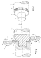
- the molding tool 1 shows a cylindrical molding tool 1, that can be driven to rotate about its longitudinal axis 1A on a machine tool, not shown, which in the figure is arranged to the right of the molding tool 1, is attached.
- the end face 2 has the molding tool 1 circumferentially arranged toothing 3.
- This interlocking 3 runs parallel to the longitudinal axis 1A of the molding tool 1.
- the toothing 2 is negative, i.e. that the spaces between the individual teeth from the Circumferential surface of the mold 1 are excluded.
- the toothing 3 extends up to the end face 2 of the mold 1, so that the peripheral edge of the end face 2 is shaped like a gear.
- a centering pin 4 is arranged in the center.
- a pressure rolling device 5 is shown, the from the mold 1 shown in Fig. 1, a Tailstock-side hollow mandrel 6 and several pressure rollers 7 consists.
- the hollow mandrel 6 is designed such that it can be pushed onto the centering pin 4 and one Blank 8, which is guided on the centering pin 4, can secure by clamping on the mold 1.
- the Hohldorn 6 is rotatably mounted, so that during a rotation of the mold 1 about its longitudinal axis 1A the mold 1, the blank 8 and the hollow mandrel 6 a rotating Form unity.
- the pressure rollers 7 each rotate about an axis of rotation 7A, which is parallel to the axis of rotation 1A of the mold 1 runs.
- the pressure rollers 7 are thus over the circumference the mold 1 distributed. You can run in parallel and moved perpendicular to the axis of rotation 1A of the mold 1 become.
- an annular one is first used Blank 8 on the centering pin 4 of the molding tool 1, whereupon the blank 8 with the Hollow mandrel 6 is fixed to the mold 1.
- the diameter of the blank 8 is larger than that of the molding tool 1, so that an edge 8a over the mold 1 survives.
- Fig. 3 is a section of the semi-finished product 9, which at the spin rolling process was shown.
- the Semi-finished product 9 is sleeve-shaped, being from the peripheral surface 10 teeth 11 stand inside. At one end of the Semi-finished product 9, the teeth 11 go into an end wall 12 about.
- the end wall 12 can be a flange that is in extends the interior of the sleeve, or as a disc, which closes the opening of the sleeve, formed his.
- the teeth 11 can vary depending on the use of the workpiece be designed differently. For example, can you do one have an annular segment cross-section, i.e. that the outer and inner peripheral surfaces by concentric Radii are formed while the side faces are formed by radial planes.
- the side faces can e.g. also formed by parallel planes be preferably parallel to a center through the tooth 11 extending radial plane.
- the length of the teeth 11 is freely selectable.
Landscapes
- Engineering & Computer Science (AREA)
- Mechanical Engineering (AREA)
- Forging (AREA)
- Shaping Metal By Deep-Drawing, Or The Like (AREA)
Description
- Fig. 1
- ein Formwerkzeug,
- Fig. 2
- eine Vorrichtung zum Drückwalzen,
- Fig. 3
- das Werkstück nach dem Drückwalzen,
- Fig. 4
- das Werkstück während einer Drehoperation und
- Fig. 5
- das fertiggestellte Werkstück mit der Stirnverzahnung.
Claims (2)
- Verfahren zur Herstellung eines stirnverzahnten Werkstückes (13) mit den folgenden Schritten:Verformen eines Rohlings (8) durch Drückwalzen zu einem hülsenförmigen innenverzahnten Halbzeug (9), dessen Zähne (11) in eine Stirnwand (12) übergehen und parallel zu der Längsachse des Halbzeuges (9) verlaufen,Abdrehen der die Zähne (11) umgebenden Umfangsfläche (10) des Halbzeuges (9), so daß bei dem Werkstück (13) die Zähne (11) einzeln von der Stirnwand (12) abstehen.
- Verfahren nach Anspruch 1, dadurch gekennzeichnet, daß der Rohling (8) ringförmig ist, und daß zum Drückwalzen des Rohlings (8) sein äußerer Flächenbereich auf ein zylinderförmiges, eine Verzahnung (3) aufweisendes Formwerkzeug (1) umgelegt wird.
Applications Claiming Priority (2)
| Application Number | Priority Date | Filing Date | Title |
|---|---|---|---|
| DE19731056A DE19731056A1 (de) | 1997-07-19 | 1997-07-19 | Verfahren zur Herstellung eines stirnverzahnten Werkstückes |
| DE19731056 | 1997-07-19 |
Publications (2)
| Publication Number | Publication Date |
|---|---|
| EP0893177A1 EP0893177A1 (de) | 1999-01-27 |
| EP0893177B1 true EP0893177B1 (de) | 2002-05-22 |
Family
ID=7836253
Family Applications (1)
| Application Number | Title | Priority Date | Filing Date |
|---|---|---|---|
| EP98112428A Expired - Lifetime EP0893177B1 (de) | 1997-07-19 | 1998-07-04 | Verfahren zur Herstellung eines stirnverzahnten Werkstückes |
Country Status (2)
| Country | Link |
|---|---|
| EP (1) | EP0893177B1 (de) |
| DE (2) | DE19731056A1 (de) |
Cited By (1)
| Publication number | Priority date | Publication date | Assignee | Title |
|---|---|---|---|---|
| EP4315566A4 (de) * | 2021-03-30 | 2025-03-26 | Metal Forming & Coining, LLC | Rotorwelle |
Families Citing this family (2)
| Publication number | Priority date | Publication date | Assignee | Title |
|---|---|---|---|---|
| US6364781B2 (en) | 1998-02-09 | 2002-04-02 | Mannesmann Sachs Ag | Installation apparatus for a coupling device having a holder, which is provided on a flywheel mass, for a driver |
| GB2352017B (en) * | 1999-07-14 | 2004-02-04 | Mannesmann Sachs Ag | Clutch assembly |
Family Cites Families (5)
| Publication number | Priority date | Publication date | Assignee | Title |
|---|---|---|---|---|
| US3396563A (en) * | 1965-10-21 | 1968-08-13 | Fellows Gear Shaper Co | Method of forming profiled objects |
| JPH0614058B2 (ja) * | 1988-08-18 | 1994-02-23 | 本田技研工業株式会社 | パルサーリングとその製造方法 |
| EP0568779B1 (de) * | 1992-05-07 | 1996-01-10 | Wf-Maschinenbau Und Blechformtechnik Gmbh & Co. Kg | Verfahren zur Herstellung eines Getriebeteiles |
| DE4446919A1 (de) * | 1994-12-28 | 1996-07-04 | Dynamit Nobel Ag | Verfahren zur Herstellung von innenverzahnten Teilen |
| EP0736347A1 (de) * | 1995-04-06 | 1996-10-09 | Samtech Corporation | Verfahren zum Herstellen eines gezahnten Übertragungselementes |
-
1997
- 1997-07-19 DE DE19731056A patent/DE19731056A1/de not_active Withdrawn
-
1998
- 1998-07-04 DE DE59804173T patent/DE59804173D1/de not_active Expired - Fee Related
- 1998-07-04 EP EP98112428A patent/EP0893177B1/de not_active Expired - Lifetime
Non-Patent Citations (1)
| Title |
|---|
| ROLOFF/MATEK: "Maschinenelemente", VIEWEG * |
Cited By (1)
| Publication number | Priority date | Publication date | Assignee | Title |
|---|---|---|---|---|
| EP4315566A4 (de) * | 2021-03-30 | 2025-03-26 | Metal Forming & Coining, LLC | Rotorwelle |
Also Published As
| Publication number | Publication date |
|---|---|
| DE19731056A1 (de) | 1999-01-21 |
| DE59804173D1 (de) | 2002-06-27 |
| EP0893177A1 (de) | 1999-01-27 |
Similar Documents
| Publication | Publication Date | Title |
|---|---|---|
| EP0725693B1 (de) | Verfahren zur spanlosen herstellung einer nabe eines die nabe aufweisenden getriebeteiles | |
| DE69830133T2 (de) | Verfahren zur Herstellung eines Getrieberades | |
| EP0882532B1 (de) | Drückwalzvorrichtung und Verfahren zur Herstellung eines planverzahnten Werkstückes | |
| DE2624854C3 (de) | Rollendrückvorrichtung zum Herstellen eines becherförmigen Riemenscheiben-Rohteils | |
| EP1108483B1 (de) | Verfahren und Vorrichtung zum Drückwalzen | |
| DE19545890C2 (de) | Verfahren zur Herstellung eines Werkstücks mit Nabe und Drück- oder Drückwalzmaschine | |
| DE3515180C2 (de) | ||
| EP0955110B1 (de) | Verfahren zum Drückwalzen und Drückwalzvorrichtung | |
| CH662760A5 (de) | Verfahren zur herstellung eines mit wenigstens einer verzahnung versehenen sintermetallkoerpers. | |
| DE2261154A1 (de) | Verfahren zum herstellen von auskehlungen an verbindungszapfen | |
| EP0568779B1 (de) | Verfahren zur Herstellung eines Getriebeteiles | |
| DE2624872C3 (de) | Verfahren zum Herstellen von ungeteilten Felgen | |
| DE4205711C2 (de) | Verfahren zur Herstellung eines außen verzahnten Getriebeteiles | |
| WO2018024417A1 (de) | Drückwalzmaschine und umformverfahren zum herstellen eines rades | |
| EP3221068B1 (de) | Verfahren zur herstellung eines rotationssymmetrischen formkörpers | |
| EP0917917A1 (de) | Verfahren und Vorrichtung zum Kaltumformen von Hohlteilen | |
| DE4321779B4 (de) | Verfahren zur Herstellung eines Starterkranz-Zahnrads aus Blech und nach dem Verfahren hergestelltes Starterkranz-Zahnrad | |
| EP0893177A1 (de) | Verfahren zur Herstellung eines stirnverzahnten Werkstückes | |
| DE1652657B2 (de) | Walzvorrichtung zum kaltwalzen von relativ duennwandigen lagerlaufringen | |
| DE2207308A1 (de) | Verfahren zur herstellung von waelzlagergehaeusen | |
| EP0555631B2 (de) | Verfahren zur Herstellung eines aussen verzahnten Getriebeteiles | |
| DE102018131508A1 (de) | Verfahren zur Herstellung einer Kugellaufbahn an einem Werkstück sowie Kugelgewindemutter mit einer derart hergestellten Kugellaufbahn | |
| DE69216301T2 (de) | Verfahren zur Herstellung einer Riemenscheibe, Vorrichtung zu ihrer Herstellung und so hergestellte Riemenscheibe | |
| DE4240613C2 (de) | Topfförmiges Werkstück mit einer axialen Innenverzahnung und einer radialen Stirnverzahnung, Verfahren zur Herstellung des Werkstücks und Vorrichtung zur Durchführung des Verfahrens | |
| EP1425120A1 (de) | Vorrichtung zur herstellung eines eine konzentrische nabe aufweisenden formkörpers |
Legal Events
| Date | Code | Title | Description |
|---|---|---|---|
| PUAI | Public reference made under article 153(3) epc to a published international application that has entered the european phase |
Free format text: ORIGINAL CODE: 0009012 |
|
| AK | Designated contracting states |
Kind code of ref document: A1 Designated state(s): DE ES FR GB IT NL SE |
|
| AX | Request for extension of the european patent |
Free format text: AL;LT;LV;MK;RO;SI |
|
| 17P | Request for examination filed |
Effective date: 19990727 |
|
| AKX | Designation fees paid |
Free format text: DE ES FR GB IT NL SE |
|
| 17Q | First examination report despatched |
Effective date: 20000713 |
|
| GRAG | Despatch of communication of intention to grant |
Free format text: ORIGINAL CODE: EPIDOS AGRA |
|
| GRAG | Despatch of communication of intention to grant |
Free format text: ORIGINAL CODE: EPIDOS AGRA |
|
| GRAH | Despatch of communication of intention to grant a patent |
Free format text: ORIGINAL CODE: EPIDOS IGRA |
|
| RAP1 | Party data changed (applicant data changed or rights of an application transferred) |
Owner name: DYNAFORM GMBH |
|
| GRAH | Despatch of communication of intention to grant a patent |
Free format text: ORIGINAL CODE: EPIDOS IGRA |
|
| GRAA | (expected) grant |
Free format text: ORIGINAL CODE: 0009210 |
|
| PG25 | Lapsed in a contracting state [announced via postgrant information from national office to epo] |
Ref country code: NL Free format text: LAPSE BECAUSE OF FAILURE TO SUBMIT A TRANSLATION OF THE DESCRIPTION OR TO PAY THE FEE WITHIN THE PRESCRIBED TIME-LIMIT Effective date: 20020522 Ref country code: IT Free format text: LAPSE BECAUSE OF FAILURE TO SUBMIT A TRANSLATION OF THE DESCRIPTION OR TO PAY THE FEE WITHIN THE PRESCRIBED TIME-LIMIT;WARNING: LAPSES OF ITALIAN PATENTS WITH EFFECTIVE DATE BEFORE 2007 MAY HAVE OCCURRED AT ANY TIME BEFORE 2007. THE CORRECT EFFECTIVE DATE MAY BE DIFFERENT FROM THE ONE RECORDED. Effective date: 20020522 Ref country code: GB Free format text: LAPSE BECAUSE OF FAILURE TO SUBMIT A TRANSLATION OF THE DESCRIPTION OR TO PAY THE FEE WITHIN THE PRESCRIBED TIME-LIMIT Effective date: 20020522 Ref country code: FR Free format text: LAPSE BECAUSE OF FAILURE TO SUBMIT A TRANSLATION OF THE DESCRIPTION OR TO PAY THE FEE WITHIN THE PRESCRIBED TIME-LIMIT Effective date: 20020522 |
|
| REG | Reference to a national code |
Ref country code: GB Ref legal event code: FG4D Free format text: NOT ENGLISH |
|
| REF | Corresponds to: |
Ref document number: 59804173 Country of ref document: DE Date of ref document: 20020627 |
|
| PG25 | Lapsed in a contracting state [announced via postgrant information from national office to epo] |
Ref country code: SE Free format text: LAPSE BECAUSE OF FAILURE TO SUBMIT A TRANSLATION OF THE DESCRIPTION OR TO PAY THE FEE WITHIN THE PRESCRIBED TIME-LIMIT Effective date: 20020822 |
|
| NLV1 | Nl: lapsed or annulled due to failure to fulfill the requirements of art. 29p and 29m of the patents act | ||
| GBV | Gb: ep patent (uk) treated as always having been void in accordance with gb section 77(7)/1977 [no translation filed] |
Effective date: 20020522 |
|
| PG25 | Lapsed in a contracting state [announced via postgrant information from national office to epo] |
Ref country code: ES Free format text: LAPSE BECAUSE OF FAILURE TO SUBMIT A TRANSLATION OF THE DESCRIPTION OR TO PAY THE FEE WITHIN THE PRESCRIBED TIME-LIMIT Effective date: 20021128 |
|
| EN | Fr: translation not filed | ||
| PG25 | Lapsed in a contracting state [announced via postgrant information from national office to epo] |
Ref country code: DE Free format text: LAPSE BECAUSE OF NON-PAYMENT OF DUE FEES Effective date: 20030201 |
|
| PLBE | No opposition filed within time limit |
Free format text: ORIGINAL CODE: 0009261 |
|
| STAA | Information on the status of an ep patent application or granted ep patent |
Free format text: STATUS: NO OPPOSITION FILED WITHIN TIME LIMIT |
|
| 26N | No opposition filed |
Effective date: 20030225 |