EP0891473B1 - AMMONIAK-EINSPRITZUNG ZUR REDUKTION DER NOx-EMMISSION - Google Patents
AMMONIAK-EINSPRITZUNG ZUR REDUKTION DER NOx-EMMISSION Download PDFInfo
- Publication number
- EP0891473B1 EP0891473B1 EP97917660A EP97917660A EP0891473B1 EP 0891473 B1 EP0891473 B1 EP 0891473B1 EP 97917660 A EP97917660 A EP 97917660A EP 97917660 A EP97917660 A EP 97917660A EP 0891473 B1 EP0891473 B1 EP 0891473B1
- Authority
- EP
- European Patent Office
- Prior art keywords
- ammonia
- injector
- exhaust gases
- engine
- exhaust
- Prior art date
- Legal status (The legal status is an assumption and is not a legal conclusion. Google has not performed a legal analysis and makes no representation as to the accuracy of the status listed.)
- Expired - Lifetime
Links
Images

Classifications
-
- F—MECHANICAL ENGINEERING; LIGHTING; HEATING; WEAPONS; BLASTING
- F01—MACHINES OR ENGINES IN GENERAL; ENGINE PLANTS IN GENERAL; STEAM ENGINES
- F01N—GAS-FLOW SILENCERS OR EXHAUST APPARATUS FOR MACHINES OR ENGINES IN GENERAL; GAS-FLOW SILENCERS OR EXHAUST APPARATUS FOR INTERNAL COMBUSTION ENGINES
- F01N3/00—Exhaust or silencing apparatus having means for purifying, rendering innocuous, or otherwise treating exhaust
- F01N3/08—Exhaust or silencing apparatus having means for purifying, rendering innocuous, or otherwise treating exhaust for rendering innocuous
- F01N3/10—Exhaust or silencing apparatus having means for purifying, rendering innocuous, or otherwise treating exhaust for rendering innocuous by thermal or catalytic conversion of noxious components of exhaust
- F01N3/24—Exhaust or silencing apparatus having means for purifying, rendering innocuous, or otherwise treating exhaust for rendering innocuous by thermal or catalytic conversion of noxious components of exhaust characterised by constructional aspects of converting apparatus
- F01N3/36—Arrangements for supply of additional fuel
-
- B—PERFORMING OPERATIONS; TRANSPORTING
- B01—PHYSICAL OR CHEMICAL PROCESSES OR APPARATUS IN GENERAL
- B01D—SEPARATION
- B01D53/00—Separation of gases or vapours; Recovering vapours of volatile solvents from gases; Chemical or biological purification of waste gases, e.g. engine exhaust gases, smoke, fumes, flue gases, aerosols
- B01D53/34—Chemical or biological purification of waste gases
- B01D53/46—Removing components of defined structure
- B01D53/54—Nitrogen compounds
- B01D53/56—Nitrogen oxides
-
- B—PERFORMING OPERATIONS; TRANSPORTING
- B01—PHYSICAL OR CHEMICAL PROCESSES OR APPARATUS IN GENERAL
- B01D—SEPARATION
- B01D53/00—Separation of gases or vapours; Recovering vapours of volatile solvents from gases; Chemical or biological purification of waste gases, e.g. engine exhaust gases, smoke, fumes, flue gases, aerosols
- B01D53/34—Chemical or biological purification of waste gases
- B01D53/74—General processes for purification of waste gases; Apparatus or devices specially adapted therefor
- B01D53/86—Catalytic processes
- B01D53/90—Injecting reactants
-
- B—PERFORMING OPERATIONS; TRANSPORTING
- B01—PHYSICAL OR CHEMICAL PROCESSES OR APPARATUS IN GENERAL
- B01D—SEPARATION
- B01D53/00—Separation of gases or vapours; Recovering vapours of volatile solvents from gases; Chemical or biological purification of waste gases, e.g. engine exhaust gases, smoke, fumes, flue gases, aerosols
- B01D53/34—Chemical or biological purification of waste gases
- B01D53/92—Chemical or biological purification of waste gases of engine exhaust gases
- B01D53/94—Chemical or biological purification of waste gases of engine exhaust gases by catalytic processes
- B01D53/9404—Removing only nitrogen compounds
- B01D53/9409—Nitrogen oxides
- B01D53/9431—Processes characterised by a specific device
-
- B—PERFORMING OPERATIONS; TRANSPORTING
- B01—PHYSICAL OR CHEMICAL PROCESSES OR APPARATUS IN GENERAL
- B01D—SEPARATION
- B01D53/00—Separation of gases or vapours; Recovering vapours of volatile solvents from gases; Chemical or biological purification of waste gases, e.g. engine exhaust gases, smoke, fumes, flue gases, aerosols
- B01D53/34—Chemical or biological purification of waste gases
- B01D53/92—Chemical or biological purification of waste gases of engine exhaust gases
- B01D53/94—Chemical or biological purification of waste gases of engine exhaust gases by catalytic processes
- B01D53/9495—Controlling the catalytic process
-
- F—MECHANICAL ENGINEERING; LIGHTING; HEATING; WEAPONS; BLASTING
- F01—MACHINES OR ENGINES IN GENERAL; ENGINE PLANTS IN GENERAL; STEAM ENGINES
- F01N—GAS-FLOW SILENCERS OR EXHAUST APPARATUS FOR MACHINES OR ENGINES IN GENERAL; GAS-FLOW SILENCERS OR EXHAUST APPARATUS FOR INTERNAL COMBUSTION ENGINES
- F01N3/00—Exhaust or silencing apparatus having means for purifying, rendering innocuous, or otherwise treating exhaust
- F01N3/08—Exhaust or silencing apparatus having means for purifying, rendering innocuous, or otherwise treating exhaust for rendering innocuous
- F01N3/10—Exhaust or silencing apparatus having means for purifying, rendering innocuous, or otherwise treating exhaust for rendering innocuous by thermal or catalytic conversion of noxious components of exhaust
- F01N3/18—Exhaust or silencing apparatus having means for purifying, rendering innocuous, or otherwise treating exhaust for rendering innocuous by thermal or catalytic conversion of noxious components of exhaust characterised by methods of operation; Control
- F01N3/20—Exhaust or silencing apparatus having means for purifying, rendering innocuous, or otherwise treating exhaust for rendering innocuous by thermal or catalytic conversion of noxious components of exhaust characterised by methods of operation; Control specially adapted for catalytic conversion ; Methods of operation or control of catalytic converters
- F01N3/2066—Selective catalytic reduction [SCR]
- F01N3/208—Control of selective catalytic reduction [SCR], e.g. dosing of reducing agent
-
- B—PERFORMING OPERATIONS; TRANSPORTING
- B01—PHYSICAL OR CHEMICAL PROCESSES OR APPARATUS IN GENERAL
- B01D—SEPARATION
- B01D2251/00—Reactants
- B01D2251/20—Reductants
- B01D2251/206—Ammonium compounds
-
- F—MECHANICAL ENGINEERING; LIGHTING; HEATING; WEAPONS; BLASTING
- F01—MACHINES OR ENGINES IN GENERAL; ENGINE PLANTS IN GENERAL; STEAM ENGINES
- F01N—GAS-FLOW SILENCERS OR EXHAUST APPARATUS FOR MACHINES OR ENGINES IN GENERAL; GAS-FLOW SILENCERS OR EXHAUST APPARATUS FOR INTERNAL COMBUSTION ENGINES
- F01N2240/00—Combination or association of two or more different exhaust treating devices, or of at least one such device with an auxiliary device, not covered by indexing codes F01N2230/00 or F01N2250/00, one of the devices being
- F01N2240/20—Combination or association of two or more different exhaust treating devices, or of at least one such device with an auxiliary device, not covered by indexing codes F01N2230/00 or F01N2250/00, one of the devices being a flow director or deflector
-
- F—MECHANICAL ENGINEERING; LIGHTING; HEATING; WEAPONS; BLASTING
- F01—MACHINES OR ENGINES IN GENERAL; ENGINE PLANTS IN GENERAL; STEAM ENGINES
- F01N—GAS-FLOW SILENCERS OR EXHAUST APPARATUS FOR MACHINES OR ENGINES IN GENERAL; GAS-FLOW SILENCERS OR EXHAUST APPARATUS FOR INTERNAL COMBUSTION ENGINES
- F01N2240/00—Combination or association of two or more different exhaust treating devices, or of at least one such device with an auxiliary device, not covered by indexing codes F01N2230/00 or F01N2250/00, one of the devices being
- F01N2240/25—Combination or association of two or more different exhaust treating devices, or of at least one such device with an auxiliary device, not covered by indexing codes F01N2230/00 or F01N2250/00, one of the devices being an ammonia generator
-
- F—MECHANICAL ENGINEERING; LIGHTING; HEATING; WEAPONS; BLASTING
- F01—MACHINES OR ENGINES IN GENERAL; ENGINE PLANTS IN GENERAL; STEAM ENGINES
- F01N—GAS-FLOW SILENCERS OR EXHAUST APPARATUS FOR MACHINES OR ENGINES IN GENERAL; GAS-FLOW SILENCERS OR EXHAUST APPARATUS FOR INTERNAL COMBUSTION ENGINES
- F01N2290/00—Movable parts or members in exhaust systems for other than for control purposes
- F01N2290/02—Movable parts or members in exhaust systems for other than for control purposes with continuous rotary movement
- F01N2290/04—Movable parts or members in exhaust systems for other than for control purposes with continuous rotary movement driven by exhaust gases
-
- F—MECHANICAL ENGINEERING; LIGHTING; HEATING; WEAPONS; BLASTING
- F01—MACHINES OR ENGINES IN GENERAL; ENGINE PLANTS IN GENERAL; STEAM ENGINES
- F01N—GAS-FLOW SILENCERS OR EXHAUST APPARATUS FOR MACHINES OR ENGINES IN GENERAL; GAS-FLOW SILENCERS OR EXHAUST APPARATUS FOR INTERNAL COMBUSTION ENGINES
- F01N2610/00—Adding substances to exhaust gases
- F01N2610/02—Adding substances to exhaust gases the substance being ammonia or urea
-
- F—MECHANICAL ENGINEERING; LIGHTING; HEATING; WEAPONS; BLASTING
- F01—MACHINES OR ENGINES IN GENERAL; ENGINE PLANTS IN GENERAL; STEAM ENGINES
- F01N—GAS-FLOW SILENCERS OR EXHAUST APPARATUS FOR MACHINES OR ENGINES IN GENERAL; GAS-FLOW SILENCERS OR EXHAUST APPARATUS FOR INTERNAL COMBUSTION ENGINES
- F01N2610/00—Adding substances to exhaust gases
- F01N2610/10—Adding substances to exhaust gases the substance being heated, e.g. by heating tank or supply line of the added substance
-
- F—MECHANICAL ENGINEERING; LIGHTING; HEATING; WEAPONS; BLASTING
- F01—MACHINES OR ENGINES IN GENERAL; ENGINE PLANTS IN GENERAL; STEAM ENGINES
- F01N—GAS-FLOW SILENCERS OR EXHAUST APPARATUS FOR MACHINES OR ENGINES IN GENERAL; GAS-FLOW SILENCERS OR EXHAUST APPARATUS FOR INTERNAL COMBUSTION ENGINES
- F01N2610/00—Adding substances to exhaust gases
- F01N2610/14—Arrangements for the supply of substances, e.g. conduits
- F01N2610/1453—Sprayers or atomisers; Arrangement thereof in the exhaust apparatus
- F01N2610/146—Control thereof, e.g. control of injectors or injection valves
-
- F—MECHANICAL ENGINEERING; LIGHTING; HEATING; WEAPONS; BLASTING
- F01—MACHINES OR ENGINES IN GENERAL; ENGINE PLANTS IN GENERAL; STEAM ENGINES
- F01N—GAS-FLOW SILENCERS OR EXHAUST APPARATUS FOR MACHINES OR ENGINES IN GENERAL; GAS-FLOW SILENCERS OR EXHAUST APPARATUS FOR INTERNAL COMBUSTION ENGINES
- F01N2900/00—Details of electrical control or of the monitoring of the exhaust gas treating apparatus
- F01N2900/04—Methods of control or diagnosing
- F01N2900/0422—Methods of control or diagnosing measuring the elapsed time
-
- F—MECHANICAL ENGINEERING; LIGHTING; HEATING; WEAPONS; BLASTING
- F01—MACHINES OR ENGINES IN GENERAL; ENGINE PLANTS IN GENERAL; STEAM ENGINES
- F01N—GAS-FLOW SILENCERS OR EXHAUST APPARATUS FOR MACHINES OR ENGINES IN GENERAL; GAS-FLOW SILENCERS OR EXHAUST APPARATUS FOR INTERNAL COMBUSTION ENGINES
- F01N2900/00—Details of electrical control or of the monitoring of the exhaust gas treating apparatus
- F01N2900/06—Parameters used for exhaust control or diagnosing
- F01N2900/08—Parameters used for exhaust control or diagnosing said parameters being related to the engine
-
- F—MECHANICAL ENGINEERING; LIGHTING; HEATING; WEAPONS; BLASTING
- F01—MACHINES OR ENGINES IN GENERAL; ENGINE PLANTS IN GENERAL; STEAM ENGINES
- F01N—GAS-FLOW SILENCERS OR EXHAUST APPARATUS FOR MACHINES OR ENGINES IN GENERAL; GAS-FLOW SILENCERS OR EXHAUST APPARATUS FOR INTERNAL COMBUSTION ENGINES
- F01N2900/00—Details of electrical control or of the monitoring of the exhaust gas treating apparatus
- F01N2900/06—Parameters used for exhaust control or diagnosing
- F01N2900/18—Parameters used for exhaust control or diagnosing said parameters being related to the system for adding a substance into the exhaust
- F01N2900/1806—Properties of reducing agent or dosing system
- F01N2900/1812—Flow rate
-
- Y—GENERAL TAGGING OF NEW TECHNOLOGICAL DEVELOPMENTS; GENERAL TAGGING OF CROSS-SECTIONAL TECHNOLOGIES SPANNING OVER SEVERAL SECTIONS OF THE IPC; TECHNICAL SUBJECTS COVERED BY FORMER USPC CROSS-REFERENCE ART COLLECTIONS [XRACs] AND DIGESTS
- Y02—TECHNOLOGIES OR APPLICATIONS FOR MITIGATION OR ADAPTATION AGAINST CLIMATE CHANGE
- Y02T—CLIMATE CHANGE MITIGATION TECHNOLOGIES RELATED TO TRANSPORTATION
- Y02T10/00—Road transport of goods or passengers
- Y02T10/10—Internal combustion engine [ICE] based vehicles
- Y02T10/12—Improving ICE efficiencies
Definitions
- a system for injecting ammonia into the exhaust gases of an engine, which increases the amount of ammonia that combines with nitrogen oxides in the exhaust gases, in a low cost system.
- ammonia instead of injecting ammonia through a single hole into the exhaust gas stream, applicant injects the ammonia through a plurality of spaced holes lying in the stream.
- applicant can mix the exhaust gases as by providing a mixer section of the exhaust gas conduit that includes mixing blades.
- Reactions of the ammonia with nitrogen oxides in the exhaust gases is greatly enhanced by activating the ammonia prior to injecting it into the stream of exhaust gases.
- the activation of the ammonia (NH 3 ) first splits it into NH 2 + H, with NH 2 being very reactive.
- the NH 2 can further decompose into NH + H, with NH also being very reactive.
- the activation of ammonia immediately prior to its injection results in the very reactive components being present at an upstream location along the flow of exhaust gases where the exhaust gases are very hot, to enhance chemical reactions.
- the activation of ammonia can be accomplished by heating it, especially in the presence of certain catalyzing materials that include metals of the platinum group, iron, nickel, and zinc, which enhance the reaction.
- One approach is to place a body packed with particles of the catalyzing material, in the stream of exhaust gases so the body is heated to a high temperature. Ammonia must pass through long narrow passages in moving through the body to outlet holes in the body, so the ammonia is heated and thereby activated as it moves through the body.
- a control that adjusts the flow of ammonia to increase or decrease it as the amount of nitrogen oxides in the exhaust gases respectively increase and decrease, does not require a specially installed sensor, Instead, applicant uses the electrical signals delivered to an injection valve of the engine, that injects fuel into air to burn therewith, as a sensor output that controls the flow rate of ammonia into the exhaust gas stream.
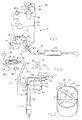
- Fig. 1 illustrates a system 10 of the present invention, wherein an engine 12 has cylinders in which fuel and air are combusted to turn a crank shaft 14.
- the combustion produces hot exhaust gases that are passed through an exhaust conduit 16 into the atmosphere.
- the exhaust conduit includes a manifold 20 that is connected to a few cylinders to collect the exhaust gases therefrom; a catalytic converter 22 that lies along the exhaust conduit, is widely used in vehicle engines to reduce pollution.
- Fig. 1 shows an ammonia injection system 30 that includes a container 32 of ammonia, such as a pressure vessel containing liquid ammonia at a pressure of about 150 psi.
- the container or source 32 delivers ammonia through a metering valve apparatus 34 and through a hose 36 to an ammonia injection location 40 that is positioned along the exhaust pipe or conduit 16.
- the location 40 where ammonia is injected into the exhaust pipe, is in or close to the exhaust manifold 20, so the ammonia encounters very hot exhaust gases (usually over 1100°F at high engine loads) to promote the reaction of ammonia and the exhaust gases to reduce nitrogen oxides.
- Fig. 2 shows some details of the engine 12 and of the ammonia injection system 30.
- An engine cylinder 50 receives air through an air manifold 52 and an inlet valve 54.
- a fuel injector 60 receives fuel from a fuel line 62 and injects the fuel through the inlet valve 54 into the cylinder, where a spark plug or the like ignites the fuel-air mixture to drive a piston 64 that is connected to the crankshaft.
- Exhaust gases created in the cylinder are exhausted through an exhaust valve 66, and to the exhaust manifold 20 which is part of the exhaust conduit 16, and eventually into the environment.
- the metering valve apparatus 34 of the ammonia injection system includes a pressure regulator 70 that supplies pressured gaseous ammonia to a solenoid valve 72. Electrical pulses delivered over a line 74 to the solenoid valve, energize a solenoid 76 to retract a valve member 78. This allows gaseous ammonia 78 lying in a chamber or conduit 80 to flow through the hose 36 to an injector 90 at location 40.
- the injector 90 injects the ammonia, or components of it, into the stream of exhaust gas 92, preferably at the location slightly downstream of the air sensor at 42.
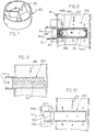
- Fig. 3 illustrates a diffuser ammonia injector 90 that applicant has constructed and successfully tested.
- the injector 90 is a tube having a diameter of 6 mm and a length of 50 mm and projecting into an exhaust conduit of a diameter D of about 60 mm.
- Applicant drilled eight holes 94 into the tube, with two holes each facing upstream, downstream, and in opposite sideward directions.
- the hose 36 carrying pressured (such as up to 10 psi, or 70 kPa) ammonia was attached to the tube as shown. Applicant found that there was a significant reduction in nitrogen oxides in the exhaust gases, as a result of the use of the diffuser construction of the injector 90, in the place of a single port opening into the exhaust pipe.
- the injector or injectors have holes 94 on primarily opposite sides of the exhaust conduit axis A.
- Figs. 4 and 5 include graphs showing variation in the levels of nitrogen oxides in the exhaust gas of an engine of an automobile (1991 Chrysler) containing an engine (8-cylinder 305 cubic inch displacement) when the automobile was driven at a speed cycle similar to that of a standard federal driving cycle.
- the speed of the engine in kilometers per hour is indicated at the right vertical axis of the graph, while the time during the test is given in seconds along the horizontal axis of the graphs.
- the emission of nitrogen oxide in ppm (parts per million) is indicated along the left vertical axis of each graph.
- FIGS. 4 and 5 indicate variation in speed of the vehicle with time, showing that the vehicle was repeatedly accelerated from 0 to 80 kph (50 miles per hour) and then decelerated to zero, during periods of about 44 seconds each, with the engine idling between these periods.
- Graphs 104 and 106 show the variation in emissions of nitrogen oxides.
- the rate of ammonia injection (0.51 liter per minute of ammonia at atmospheric pressure at a constant speed of 10 mph, with the rate proportional to fuel flow) in Figs. 4 and 5 were substantially the same (per unit fuel) during each test.
- the difference between Figs. 4 and 5, is that in Fig. 4 ammonia was injected through a single port directed downstream (as shown in U.S.
- Fig. 6 contains a graph 110 showing variation in nitrogen oxides during the same type of vehicle operating cycles shown in Figs. 4 and 5 (speed indicated by graph 112), and using the same injector as for Fig. 5, except that in Fig. 6 the amount of injected ammonia was reduced by 25%. This indicates that there should be close control of the amount of ammonia, so that there is neither too little nor too much. When no ammonia was injected, the amount of nitrogen oxides was about twice as great as the amount shown in Fig. 4.
- Fig. 7 shows a mixer section 120 that can be installed in the exhaust pipe (either slightly upstream or downstream of the injector) to cause a swirling of the exhaust gases near the injection location. Such swirling helps to rapidly distribute injected ammonia throughout the exhaust gas while it is still hot.
- the particular mixer section 120 includes stationary mixing blades 122 which direct the gas into a swirl.
- the length of the mixer section 122 can be minimal, so the injector lies close to the exhaust manifold.
- a variety of mixers can be used, including those with a rotating fan blade and those where turbulence is created immediately downstream of the injector. In all of these, care must be taken to not significantly block the outflow of exhaust gases.
- ammonia in order for ammonia to react with nitrogen oxides, the ammonia must first start to decompose.
- Ammonia (NH 3 ) first splits into NH 2 + H.
- the NH 2 is a very reactive form which can readily react with nitrogen oxides.
- the NH 2 can further decompose into NH + H with NH also being reactive.
- the decomposition of ammonia into NH 2 and/or NH, + H begins (in the absence of a catalyst) at temperatures in the range of 900 to 1000 degrees F, and is essentially complete at 1800°F.
- the decomposition occurs at lower temperatures, usually starting at about 500°F and being essentially complete at 1100°F. It is also known that the decomposition of NH 3 tends to occur in the presence of certain materials in addition to metals of the platinum group, including iron, nickel, and zinc. When ammonia is split into the components NH 2 and/or NH, +H, these components combine back into ammonia when the decomposing environment is no longer present.
- applicant decomposes, or activates, ammonia (NH 3 ) to convert a substantial portion of it (at least 10% and preferably at least 20%) into its active components NH 2 and/or NH shortly before or during injection of ammonia into the stream of engine exhaust gases.
- ammonia NH 3
- injecting ammonia includes injecting ammonia that has not decomposed as well as ammonia that has decomposed.
- Fig. 8 shows one example of an ammonia injector 130 which is constructed to activate ammonia immediately prior to or during injection.
- the injector 130 includes a housing 132 with an inlet 134, and with an outlet formed by six holes 136 lying in the exhaust conduit 16.
- Numerous particles 140 of a catalytic material (which is catalytic to NH 3 ) such as a metal of the platinum group, iron, nickel, or zinc are held in the housing, with a screen 142 being used to prevent their loss.
- Pumped in ammonia passes between the granules prior to exiting through the holes 136.
- the granules activate the ammonia (NH 3 ) by splitting some of it into its reactive components prior to exit of the gas into the exhaust gas stream 92.
- Activation is enhanced by the fact that the granules 140 are heated to a high temperature by the exhaust gases passing over the injector.
- the granules can be heated by a heater element 146 connected to a current source 148.
- the ammonia itself can be preheated prior to reaching the injector.
- the housing 132 of the injector 130 of Fig. 8 is somewhat similar to the injector 90 of Fig. 3, in that it includes a plurality of holes 136 (6 being indicated) to distribute the ammonia throughout the exhaust gases.
- Applicant prefers to use granules of a small size, such as of a diameter of no more than about 2 mm, and preferably much less. This results in narrow passages between adjacent granules, with the narrow passages having an average cross-section of no more than about one square millimeter, and preferably no more than 0.1 mm 2 .
- the ammonia moves along a hot passage (spaces between granules) having a length more than ten times its average width (preferably more than 50 times its width), resulting in considerable heating of the ammonia which results in activating it.
- the narrow and long passages also aid in bringing the ammonia into contact with the catalytic material of the granules, to help activate it, in addition to heating the ammonia (preferably to at least 500°F or 260°C).
- Fig. 9 illustrates another injector 150 which is similar to that of Fig. 8, except that the injector of Fig. 9 is formed of sintered particles of a catalytic material, with the ammonia exiting through pores in the sintered injector into the gas stream 92.
- a passage 152 has been formed in the center of the injector to more evenly distribute the ammonia.
- Fig. 10 illustrates another injector 160 wherein arcs at 162 are created to activate ammonia.
- the injector includes electrodes 164, 166 and a high voltage (e.g. 20 kilovolts) source 168 connected between the electrodes to produce activating arcs through which the ammonia passes.
- a high voltage e.g. 20 kilovolts
- Any input of energy to ammonia such as from a laser beam, electron beam, etc. immediately prior to ammonia injection (preferably less than a minute and more preferably less than ten seconds, and while the ammonia is moving toward or through the injector), can help to activate the ammonia.
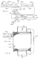
- the fuel injector 60 which injects fuel into the cylinder 50, is energized by electrical pulses 170 received from a circuit 172.
- the width of each pulse determines how long the valve is open during each cycle, to thereby determine how much fuel is delivered to the cylinder of the engine.
- a wire 176 (actually at least two wires are required) carries the same output pulses 170 that are delivered to the fuel injector, to a circuit 180 that controls operation of the solenoid valve 72 that meters the flow of ammonia to an ammonia injector such as 90.
- Gaseous ammonia is supplied to the valve member 78 at a valve conduit 80 where gaseous ammonia is at a predetermined pressure that is usually 10 psi or less (e.g. 2 to 5 psi, depending on the particular engine) as regulated by the pressure regulator 70.
- a pulse 182 is delivered by circuit 180 to the solenoid 76, the solenoid pulls the valve member 78 to open it for a short time, to deliver ammonia to the hose 36 that carries it to the injector.
- the width of the pulse 182 determines how long the valve member 78 will lie in its open position, and therefore determines the amount of ammonia that will be dispensed. It is noted that ammonia flow from the hose 36 and through the injector 90 into the exhaust pipe or conduit 16 is substantially continuous and without pulses.
- an automobile is moving at 40 mph, with its engine rotating at 1800 rpm or 30 rps (revolutions per second).
- the circuit 172 that delivers electrical pulses to the fuel injectors, delivers 15 pulses per second to each of 8 cylinders. Applicant takes the electrical output on one of the eight lines, which carries 15 pulses per second, or one pulse every 67 ms (milliseconds).
- the circuit 180 can merely amplify these pulses, but preferably divides them so as to produce less frequent pulses on line 74, such as one pulse every 670 ms.
- Fig. 11 provides an example of the circuit 180, which receives pulses 170 every one-fifteenth second, or every 67 ms on line 176.
- each pulse to the fuel injector has a duration of 8 ms to produce a predetermined fuel flow and power output.
- the fuel injecting pulses on line 176 are delivered to a counter 200, which applicant assumes to count by ten to aid in the illustration.
- the counter output on line 202 has positive going edges at 204, 206 that are spaced apart by 670 milliseconds, or ten times the spacing of the original pulses.
- the output on line 202 is delivered to a pulse generator 210 which delivers pulses on line 74, with their leading edges 214, 216 being spaced apart by 670 milliseconds.
- the duration of each pulse is determined by a pulse width detector circuit 220 which detects the duration (e.g. 8 ms) of each fuel injection pulse 170 on line 176, and whose output 222 is a count indicating the duration of the desired pulse.
- the output 222 is delivered to the pulse generator 210, to determine the duration of each pulse, with the particular pulse output 224 having a duration of 80 rns.
- the duration of fuel injection signals or the proportion of the time they exist (e.g. 8 ms every 67 ms, or 12% of the time), is used to control the flow rate of ammonia into the exhaust conduit.
- a divider circuit 180 enables the use of a solenoid valve which has a much slower reaction time, and which is therefore of lower cost.
- the electronics for amplifying the fuel injector pulses and dividing them, is of relatively low cost, compared to the cost of providing a separate sensor along the air manifold, fuel line, or exhaust manifold, installing the sensor, and providing a circuit to process the signals. It should be noted that an additional circuit 226 (Fig.
- the pulse generator 11 is provided to control the pulse generator so no pulses are delivered during idling of a hot engine and to otherwise vary the ammonia flow in accordance with engine operation.
- the flow rate of ammonia is generally increased and decreased as the duration of fuel valve pulses respectively increases and decreases.
- Fig. 12 illustrates a system 230 that is based on a system described in U.K. patent application 2,274,412A. That patent application describes a bed 232 of pellets 234 that have a high dielectric constant and ferro-electric properties, such as barium titanate. A pair of metal grids 240, 242 lie at opposite ends of the bed and are connected to a high voltage source (e.g. 20 kilovolts) 244. The bed helps to reduce nitrogen oxides (even in the absence of ammonia), as well as oxidizing soot particles. It is noted that the exhaust gas stream 92 passes through the bed 232, rather than merely passing by (i.e. near) the bed.
- a high voltage source e.g. 20 kilovolts
- applicant connects an ammonia source 246 (including a tank, metering valve, and control) to an inlet 250 near the upstream end of the bed 234.
- an ammonia source 246 including a tank, metering valve, and control
- the presence of barium titanate particles and the ionizing energy from the high voltage source 244, promotes the activation of ammonia, with the bed also helping to mix the ammonia into the exhaust gases.
- the invention provides a system for injecting ammonia or its components into a stream of exhaust gases from an engine, which effectively uses the ammonia to reduce nitrogen oxide emissions.
- the ammonia is injected into the exhaust gas conduit at several spaced locations to help distribute the ammonia throughout the exhaust gases while they are still very hot.
- the ammonia is activated, so at least ten percent of the ammonia is split into NH 2 and/or NH so these highly reactive components are injected into the exhaust gas stream to begin reactions while the exhaust gas is very hot.
- the ammonia can be broken down by heating it, especially by passing the ammonia through long narrow passages whose walls are forrned of a catalyzing material such as a metal of the platinum group, iron, nickel, or zinc.
- the injector with holes through which ammonia is injected into the exhaust gas stream preferably includes a body lying within the exhaust gas stream to be heated to a high temperature (at least 500°F) thereat, to heat ammonia passing therethrough.
- a high temperature at least 500°F
Landscapes
- Engineering & Computer Science (AREA)
- Chemical & Material Sciences (AREA)
- Chemical Kinetics & Catalysis (AREA)
- Health & Medical Sciences (AREA)
- Environmental & Geological Engineering (AREA)
- Combustion & Propulsion (AREA)
- Biomedical Technology (AREA)
- Analytical Chemistry (AREA)
- General Chemical & Material Sciences (AREA)
- Oil, Petroleum & Natural Gas (AREA)
- Toxicology (AREA)
- Mechanical Engineering (AREA)
- General Engineering & Computer Science (AREA)
- Exhaust Gas After Treatment (AREA)
Claims (17)
- Vorrichtung zur Aufnahme von Ammoniak (78) und zum Einspritzen zumindest Komponenten davon in einen Strom von Abgasen (92) eines Motors (12), wobei die Verbesserung umfasst:Mittel zum Aktivieren des Ammoniaks (130, 150, 164, 166, 232), um zumindest einen Teil davon in Ammoniak-Komponenten aufzuspalten, bevor das aktivierte Ammoniak in den Strom von Abgasen eingespritzt wird.
- Vorrichtung nach Anspruch 1, worin:das Mittel zum Aktivieren so konstruiert ist, dass zumindest 10 % des Ammoniaks in seine Komponenten aufgespalten werden, bevor das Ammoniak und seine Komponenten in den Strom von Abgasen eingespritzt werden.
- Vorrichtung nach Anspruch 1, worin:das Mittel zum Aktivieren ein Rohr, von dem ein Abschnitt im Strom von Abgasen liegt, sowie einen Körper (140, 150) umfasst, der Material umfasst, das Ammoniak katalysiert, um Ammoniak aufzuspalten, wobei der Körper im Rohrabschnitt liegt, wobei der Körper mehrere Ammoniak-Durchgänge aufweist, die parallel geschaltet sind.
- Vorrichtung nach Anspruch 1, worin:das Mittel zum Aktivieren einen Körper (140, 150), der mehrere Ammoniak führende Durchgänge aufweist, die jeweils einen Querschnitt von weniger als 1 mm2 aufweisen, sowie eine mit Elektrizität betriebene Heizeinrichtung (146) umfasst, die an den Körper gekoppelt ist, um ihn zu erhitzen.
- Vorrichtung nach Anspruch 1, worin:das Mittel zum Aktivieren einen Körper (150) aus gesinterten Teilchen umfasst, die mikroskopische Durchgänge bilden, wobei der Körper so angeordnet ist, das er von den Abgasen erhitzt wird.
- Motor (12), der Mittel (50, 64) zum Verbrennen von Kohlenwasserstoffen in Luft umfasst, um Arbeit zu erzeugen, worin das Mittel auch einen Strom von Abgasen (92) erzeugt, die Stickstoffoxide enthalten, wobei der Motor eine Auspuffleitung (16) aufweist, durch die die Abgase hindurchgeführt werden, bevor sie an die Atmosphäre abgegeben werden, wobei die Verbesserung umfasst:wobei die Einspritzvorrichtung eine Ammoniak führende Leitung (36) mit einem Injektor (90, 130, 150, 160, 250) umfasst, der innerhalb der Abgasleitung liegt, wobei der Injektor zumindest eine Auslassöffnung (94, 136) aufweist, durch die das Ammoniak in den Strom von Abgasen eingespritzt wird;eine Ammoniakquelle (32, 246);eine Einspritzvorrichtung (30, 230), die an die Quelle gekoppelt ist, um Ammoniak davon zu erhalten und es in die Abgasleitung einzuspritzen;
Mittel (130, 150), um das Ammoniak zu erhitzen und es an einem Katalysatormaterial (140) vorbei strömen zu lassen, um das Ammoniak zu aktivieren, um zumindest einen Teil davon in Ammoniak-Komponenten aufzuspalten, nachdem es die Quelle verlassen hat und bevor es in die Abgasleitung eingespritzt worden ist. - Motor nach Anspruch 6, worin:das Mittel zum Erhitzen einen Körper (140, 150) umfasst, der eine Vielzahl von Durchgangsabschnitten aufweist, die innerhalb der Abgasleitung liegen und die jeweils eine Dicke von nicht mehr als 1 mm und eine Länge aufweisen, die mehr als das Zehnfache ihrer mittleren Dicke beträgt, so dass der Körper von Abgasen erhitzt wird und seinerseits Ammoniak erhitzt, das durch den Durchgangsabschnitt hindurchgeht, um das Ammoniak zu aktivieren.
- Motor nach Anspruch 6, worin das Mittel zum Verbrennen ein Treibstoffinjektorventil (60) und einen Injektor (130, 150, 160), der so angeordnet ist, dass er die Kohlenwasserstoffe in die Luft einspritzt, um ein Treibstoff-Luft-Gemisch zur Verbrennung zu erzeugen, sowie eine elektronische Treibstoffinjektorschaltung (17) umfasst, die elektrische Ströme (170) erzeugt, deren Zeitdauer zumindest teilweise die mittlere Strömungsrate von Brennstoff bestimmt, der in die Luft einspritzt wird, wobei die Verbesserung umfasst:eine Ammoniakeinspritzvorrichtung (30), die den Injektor und einen Regler (180) umfasst, der an die elektronische Treibstoffinjektorschaltung und an das Ventil angeschlossen ist und den Betrieb des Ventils steuert, um die Strömungsrate von Ammoniak, das durch den Injektor in die Abgasleitung eingespritzt wird, mit der Zunahme und Abnahme der mittleren Zeitdauer der elektrischen Ströme zu erhöhen bzw. zu verringern.
- Motor nach Anspruch 6, worin:der Injektor einen Körper (150) aus gesinterten Teilchen umfasst, die mikroskopische Durchgänge bilden.
- Verfahren zur Reduktion von Stickstoffoxiden in den Abgasen eines Motors, der Kohlenwasserstoff in Gegenwart von Luft verbrennt und der einen Strom von Abgasen erzeugt, umfassend:das Leiten von Ammoniak von einer Quelle (32, 246) zu einem Injektor (90, 130, 150, 160, 250) und das Einspritzen zumindest von Komponenten des Ammoniak aus dem Injektor in den Strom von Abgasen;das Aktivieren zumindest eines Teils des Ammoniaks, um zumindest einen Teil davon in Ammoniak-Komponenten aufzuspalten, vor dem Einspritzen des Ammoniaks in den Strom von Abgasen.
- Verfahren nach Anspruch 10, worin:der Schritt des Aktivierens das Anordnen eines Körpers (90, 130, 150, 160) mit Durchgangswänden, die zumindest einen länglichen Durchgang bilden, im Strom von Abgasen und das Erhitzen der Durchgangswände durch die Wärme der Abgase, sowie das Hindurchleiten des Ammoniaks durch den zumindest einen Durchgang umfasst, bevor es in den Strom von Abgasen eingespritzt wird, um zu ermöglichen, dass die Durchgangswände das Ammoniak auf zumindest 500 °F erhitzt werden.
- Verfahren nach Anspruch 10, worin:der Schritt des Aktivierens das Aktiveren des Ammoniaks, um mehr als 10 % des Ammoniaks in NH2 und NH und Wasserstoff aufzuspalten, innerhalb von 10 s nach dem Einspritzen von Ammoniak in den Strom von Abgasen umfasst.
- Verfahren nach Anspruch 10, worin:der Schritt des Aktivierens das Erhitzen des Ammoniaks in Gegenwart eines Katalysators vor dem Schritt des Einspritzens umfasst.
- Verfahren nach Anspruch 10, worin:der Schritt des Aktivierens das Erhitzen des Ammoniaks auf eine Temperatur von zumindest 500 °F in Gegenwart eines Katalysators vor dem Schritt des Einspritzens umfasst.
- Motor nach Anspruch 6, worin der Motor (12) eine Treibstoffinjektorvorrichtung (60, 172) aufweist, die so angeordnet ist, dass Kohlenwasserstoff-Treibstoff in Luftmassen eingespritzt wird, um sie zu verbrennen und Arbeit zu erzeugen und auch einen Strom von Abgasen zu erzeugen, die Stickstoffoxide enthalten, wobei der Motor eine Auspuffleitung (16) aufweist, durch die der Strom von Abgasen strömt, bevor er an die Umgebung abgegeben wird, und wobei die Treibstoffinjektorvorrichtung eine elektronische Treibstoffinjektorschaltung (172) umfasst, die elektrische Ströme (170) erzeugt, deren Zeitdauer zumindest teilweise die mittlere Strömungsrate von Treibstoff bestimmt, der in die Luftmassen eingespritzt wird, worin:die Injektorvorrichtung (30) einen Injektor (96, 130, 150, 160), der an die Abgasleitung gekoppelt ist, um Ammoniak in den Strom von Abgasen einzuspritzen, sowie eine Steuerung (180) umfasst, die an die elektronische Treibstoffinjektorschaltung gekoppelt ist und den Betrieb der Injektorvorrichtung steuert, um die Strömungsrate von Ammoniak, das vom Injektor in die Abgasleitung eingespritzt wird, mit Zunahme und Abnahme der mittleren Zeitdauer der elektrischen Ströme zu erhöhen bzw. zu verringern.
- Motor nach Anspruch 15, worin:wobei die Steuerung eine Teilerschaltung (200, 220, 210), die Steuersignale (182) erzeugt, die jeweils eine Dauer haben, die ein vorbestimmtes Vielfaches von mehr als einem der elektrischen Ströme ist, die von der elektronischen Treibstoffinjektorschaltung erzeugt werden, sowie einen elektrischen Leiter (74) umfasst, der die Steuersignale zum Ventil leitet, um es für Zeiträume zu öffnen, die der Dauer eines der Steuersignale entsprechen.die Ammoniak-Einspritzvorrichtung eine Quelle für unter Druck stehendes Ammoniak (32), ein elektrisch betätigtes Ventil (72) sowie Wände umfasst, die einen Ammoniak führenden Durchgang (36) bilden, der sich durch das Ventil hindurch von der Quelle zum Injektor erstreckt;
- Verfahren nach Anspruch 10, worin der Schritt des Leitens von Ammoniak zu einem Injektor das Steuern der Einspritzung von Ammoniak durch ein elektrisch betätigtes Ventil (72) in eine Abgasleitung eines Motors (16) umfasst, wobei der Motor einen Treibstoffinjektor (66) und eine elektronische Treibstoffinjektorschaltung (172) umfasst, die Treibstoffeinspritz-Steuerströme (170) erzeugt, deren mittlere Dauer pro Zeiteinheit die Strömungsrate von Treibstoff durch den Treibstoffinjektor bestimmt, umfassend:die Verwendung der Treibstoffeinspritz-Steuerströme (182), um das Öffnen des Ventils (72) zu steuern, um Ammoniak mit einer Strömungsrate durch das Ventil strömen zu lassen, die im Allgemeinen proportional zur Dauer pro Zeiteinheit der Einspritzsteuerströme ist.
Applications Claiming Priority (5)
| Application Number | Priority Date | Filing Date | Title |
|---|---|---|---|
| US1466096P | 1996-04-02 | 1996-04-02 | |
| US14660P | 1996-04-02 | ||
| US2000796P | 1996-06-18 | 1996-06-18 | |
| US20007P | 1996-06-18 | ||
| PCT/US1997/005012 WO1997039226A1 (en) | 1996-04-02 | 1997-03-27 | AMMONIA INJECTION IN NOx CONTROL |
Publications (3)
| Publication Number | Publication Date |
|---|---|
| EP0891473A1 EP0891473A1 (de) | 1999-01-20 |
| EP0891473A4 EP0891473A4 (de) | 1999-06-02 |
| EP0891473B1 true EP0891473B1 (de) | 2002-03-13 |
Family
ID=26686344
Family Applications (1)
| Application Number | Title | Priority Date | Filing Date |
|---|---|---|---|
| EP97917660A Expired - Lifetime EP0891473B1 (de) | 1996-04-02 | 1997-03-27 | AMMONIAK-EINSPRITZUNG ZUR REDUKTION DER NOx-EMMISSION |
Country Status (7)
| Country | Link |
|---|---|
| EP (1) | EP0891473B1 (de) |
| JP (1) | JP3391799B2 (de) |
| AU (1) | AU2592497A (de) |
| BR (1) | BR9708591A (de) |
| DE (1) | DE69711031T2 (de) |
| ES (1) | ES2173437T3 (de) |
| WO (1) | WO1997039226A1 (de) |
Cited By (1)
| Publication number | Priority date | Publication date | Assignee | Title |
|---|---|---|---|---|
| US11143078B2 (en) | 2019-12-17 | 2021-10-12 | Caterpillar Inc. | Aftertreatment system and method |
Families Citing this family (12)
| Publication number | Priority date | Publication date | Assignee | Title |
|---|---|---|---|---|
| DE19946901A1 (de) * | 1999-09-30 | 2001-04-05 | Bosch Gmbh Robert | Vorrichtung zur Beaufschlagung eines strömenden Gases mit einem Reaktionsmittel |
| DE10052378A1 (de) * | 2000-10-20 | 2002-04-25 | Messer Griesheim Gmbh | Sicheres Entnehmen von flüssigem Ammoniak aus Gasflaschen zu Reduzierung von NOx im Abgasstrom von Verbrennungsmaschinen |
| SE528119C2 (sv) * | 2004-08-06 | 2006-09-05 | Scania Cv Ab | Arrangemang för att tillföra ett medium till en avgasledning hos en förbränningsmotor |
| US7842266B2 (en) * | 2006-01-06 | 2010-11-30 | Mitsui Engineering & Shipbuilding Co., Ltd. | Method of denitration of exhaust gas and apparatus therefor |
| JP4817850B2 (ja) * | 2006-01-13 | 2011-11-16 | 三井造船株式会社 | 排ガス処理装置 |
| DE102007022678A1 (de) | 2007-05-11 | 2008-11-13 | Hydraulik-Ring Gmbh | Abgasnachbehandlungseinheit auf Ammoniakbasis und Verfahren zur Reinigung stickoxidhaltiger Abgase von Verbrennungskraftmaschinen |
| JP4861974B2 (ja) * | 2007-12-21 | 2012-01-25 | 三菱ふそうトラック・バス株式会社 | エンジンの排気浄化装置 |
| JP4764463B2 (ja) * | 2008-09-22 | 2011-09-07 | 株式会社日本自動車部品総合研究所 | 内燃機関の排気浄化制御装置及び排気浄化システム |
| EP2527611B1 (de) * | 2011-05-26 | 2016-11-09 | Wärtsilä Schweiz AG | Vorrichtung und Verfahren zur Abgasnachbehandlung |
| FR3020765B1 (fr) * | 2014-05-06 | 2020-02-07 | Psa Automobiles Sa. | Injecteur de reducteur d'oxydes d'azote a decomposition amelioree du reducteur |
| EP3321483B1 (de) * | 2016-11-11 | 2019-07-10 | Perkins Engines Company Limited | Dieselabgasflüssigkeitsinjektor |
| CN115025602B (zh) * | 2022-07-18 | 2023-04-25 | 怀化蕲黄节能环保设备有限公司 | 一种生物质锅炉烟气脱硝处理设备 |
Family Cites Families (4)
| Publication number | Priority date | Publication date | Assignee | Title |
|---|---|---|---|---|
| US4403473A (en) * | 1981-06-22 | 1983-09-13 | Caterpillar Tractor Co. | Ammonia/fuel ratio control system for reducing nitrogen oxide emissions |
| KR950012137B1 (ko) * | 1989-02-02 | 1995-10-14 | 닛뽄 쇼크바이 카가꾸 고오교오 가부시기가이샤 | 디이젤엔진 배기가스 중의 질소산화물 제거방법 |
| EP0683311A1 (de) * | 1991-06-03 | 1995-11-22 | Isuzu Motors Limited | VORRICHTUNG ZUR REDUZIERUNG VON NOx - EMISSIONEN |
| DE4217552C1 (de) * | 1992-05-27 | 1993-08-19 | Mercedes-Benz Aktiengesellschaft, 7000 Stuttgart, De |
-
1997
- 1997-03-27 DE DE69711031T patent/DE69711031T2/de not_active Expired - Fee Related
- 1997-03-27 WO PCT/US1997/005012 patent/WO1997039226A1/en active IP Right Grant
- 1997-03-27 ES ES97917660T patent/ES2173437T3/es not_active Expired - Lifetime
- 1997-03-27 AU AU25924/97A patent/AU2592497A/en not_active Abandoned
- 1997-03-27 EP EP97917660A patent/EP0891473B1/de not_active Expired - Lifetime
- 1997-03-27 JP JP53710797A patent/JP3391799B2/ja not_active Expired - Fee Related
- 1997-03-27 BR BR9708591-0A patent/BR9708591A/pt not_active IP Right Cessation
Cited By (1)
| Publication number | Priority date | Publication date | Assignee | Title |
|---|---|---|---|---|
| US11143078B2 (en) | 2019-12-17 | 2021-10-12 | Caterpillar Inc. | Aftertreatment system and method |
Also Published As
| Publication number | Publication date |
|---|---|
| JP3391799B2 (ja) | 2003-03-31 |
| EP0891473A4 (de) | 1999-06-02 |
| ES2173437T3 (es) | 2002-10-16 |
| WO1997039226A1 (en) | 1997-10-23 |
| DE69711031T2 (de) | 2002-11-14 |
| DE69711031D1 (de) | 2002-04-18 |
| BR9708591A (pt) | 2000-01-04 |
| JP2000507665A (ja) | 2000-06-20 |
| AU2592497A (en) | 1997-11-07 |
| EP0891473A1 (de) | 1999-01-20 |
Similar Documents
| Publication | Publication Date | Title |
|---|---|---|
| US5992141A (en) | Ammonia injection in NOx control | |
| EP0891473B1 (de) | AMMONIAK-EINSPRITZUNG ZUR REDUKTION DER NOx-EMMISSION | |
| US7000383B2 (en) | Diesel aftertreatment systems | |
| US6895747B2 (en) | Diesel aftertreatment systems | |
| RU2219354C2 (ru) | СПОСОБ И УСТРОЙСТВО ДЛЯ НЕЙТРАЛИЗАЦИИ СОДЕРЖАЩИХ ОКСИДЫ АЗОТА (NOx) ОТРАБОТАВШИХ ГАЗОВ ДВИГАТЕЛЯ ВНУТРЕННЕГО СГОРАНИЯ | |
| RU2109976C1 (ru) | Способ работы двигателя внутреннего сгорания и устройство для введения горючего в него | |
| US5609026A (en) | Engine NOx reduction | |
| USRE44753E1 (en) | Procedure and device to heat a reducing agent generation system | |
| EP1590558A2 (de) | Verfahren und vorrichtung zur kraftstoffverbrennung | |
| US7550126B2 (en) | NOx augmentation in exhaust gas simulation system | |
| GB2319192A (en) | System for injecting nitrogen oxide reducer into an exhaust gas flow | |
| US6530215B2 (en) | Method and apparatus for processing exhaust gas from an internal combustion engine | |
| EP0638139B1 (de) | VORRICHTUNG ZUR NOx-REDUKTION VON BRENNKRAFTMASCHINEN | |
| US5381659A (en) | Engine exhaust reburner system and method | |
| US6862879B2 (en) | Diesel aftertreatment system | |
| US5381660A (en) | Engine exhaust reburner system and method | |
| US20050160671A1 (en) | Fuel reforming apparatus | |
| KR100299064B1 (ko) | 연소기관용연소유도장치 | |
| JP3460391B2 (ja) | 内燃機関 | |
| EP0698655A1 (de) | Methode und vorrichtung zur herstellung von brenngas | |
| KR19990027818A (ko) | 가솔린 엔진의 버너 가열식 삼원촉매 변환장치 | |
| RU2098717C1 (ru) | Способ сжигания топлива с воздухом и устройство для его осуществления | |
| KR100203763B1 (ko) | 디젤엔진 질소산화물 처리장치의 연료수소분리장치 | |
| KR100231556B1 (ko) | 디젤엔진의 배기가스 처리방법 | |
| JPH07243325A (ja) | 触媒方法 |
Legal Events
| Date | Code | Title | Description |
|---|---|---|---|
| PUAI | Public reference made under article 153(3) epc to a published international application that has entered the european phase |
Free format text: ORIGINAL CODE: 0009012 |
|
| 17P | Request for examination filed |
Effective date: 19981022 |
|
| AK | Designated contracting states |
Kind code of ref document: A1 Designated state(s): DE ES FR GB IT SE |
|
| A4 | Supplementary search report drawn up and despatched |
Effective date: 19990415 |
|
| AK | Designated contracting states |
Kind code of ref document: A4 Designated state(s): DE ES FR GB IT NL SE |
|
| TPAD | Observations filed by third parties |
Free format text: ORIGINAL CODE: EPIDOS TIPA |
|
| 17Q | First examination report despatched |
Effective date: 20000623 |
|
| GRAG | Despatch of communication of intention to grant |
Free format text: ORIGINAL CODE: EPIDOS AGRA |
|
| GRAG | Despatch of communication of intention to grant |
Free format text: ORIGINAL CODE: EPIDOS AGRA |
|
| GRAH | Despatch of communication of intention to grant a patent |
Free format text: ORIGINAL CODE: EPIDOS IGRA |
|
| GRAH | Despatch of communication of intention to grant a patent |
Free format text: ORIGINAL CODE: EPIDOS IGRA |
|
| REG | Reference to a national code |
Ref country code: GB Ref legal event code: IF02 |
|
| GRAA | (expected) grant |
Free format text: ORIGINAL CODE: 0009210 |
|
| RBV | Designated contracting states (corrected) |
Designated state(s): DE ES FR GB IT SE |
|
| AK | Designated contracting states |
Kind code of ref document: B1 Designated state(s): DE ES FR GB IT SE |
|
| REF | Corresponds to: |
Ref document number: 69711031 Country of ref document: DE Date of ref document: 20020418 |
|
| ET | Fr: translation filed | ||
| REG | Reference to a national code |
Ref country code: ES Ref legal event code: FG2A Ref document number: 2173437 Country of ref document: ES Kind code of ref document: T3 |
|
| PLBE | No opposition filed within time limit |
Free format text: ORIGINAL CODE: 0009261 |
|
| STAA | Information on the status of an ep patent application or granted ep patent |
Free format text: STATUS: NO OPPOSITION FILED WITHIN TIME LIMIT |
|
| 26N | No opposition filed |
Effective date: 20021216 |
|
| REG | Reference to a national code |
Ref country code: GB Ref legal event code: 732E |
|
| REG | Reference to a national code |
Ref country code: FR Ref legal event code: TP |
|
| PGFP | Annual fee paid to national office [announced via postgrant information from national office to epo] |
Ref country code: ES Payment date: 20080326 Year of fee payment: 12 |
|
| PGFP | Annual fee paid to national office [announced via postgrant information from national office to epo] |
Ref country code: GB Payment date: 20080328 Year of fee payment: 12 |
|
| PGFP | Annual fee paid to national office [announced via postgrant information from national office to epo] |
Ref country code: DE Payment date: 20080530 Year of fee payment: 12 |
|
| PGFP | Annual fee paid to national office [announced via postgrant information from national office to epo] |
Ref country code: SE Payment date: 20080331 Year of fee payment: 12 |
|
| PGFP | Annual fee paid to national office [announced via postgrant information from national office to epo] |
Ref country code: IT Payment date: 20080331 Year of fee payment: 11 Ref country code: FR Payment date: 20080331 Year of fee payment: 12 |
|
| PG25 | Lapsed in a contracting state [announced via postgrant information from national office to epo] |
Ref country code: IT Free format text: LAPSE BECAUSE OF NON-PAYMENT OF DUE FEES Effective date: 20080327 |
|
| EUG | Se: european patent has lapsed | ||
| GBPC | Gb: european patent ceased through non-payment of renewal fee |
Effective date: 20090327 |
|
| REG | Reference to a national code |
Ref country code: FR Ref legal event code: ST Effective date: 20091130 |
|
| PG25 | Lapsed in a contracting state [announced via postgrant information from national office to epo] |
Ref country code: DE Free format text: LAPSE BECAUSE OF NON-PAYMENT OF DUE FEES Effective date: 20091001 |
|
| PG25 | Lapsed in a contracting state [announced via postgrant information from national office to epo] |
Ref country code: GB Free format text: LAPSE BECAUSE OF NON-PAYMENT OF DUE FEES Effective date: 20090327 Ref country code: FR Free format text: LAPSE BECAUSE OF NON-PAYMENT OF DUE FEES Effective date: 20091123 |
|
| REG | Reference to a national code |
Ref country code: ES Ref legal event code: FD2A Effective date: 20090328 |
|
| PG25 | Lapsed in a contracting state [announced via postgrant information from national office to epo] |
Ref country code: ES Free format text: LAPSE BECAUSE OF NON-PAYMENT OF DUE FEES Effective date: 20090328 |
|
| PG25 | Lapsed in a contracting state [announced via postgrant information from national office to epo] |
Ref country code: SE Free format text: LAPSE BECAUSE OF NON-PAYMENT OF DUE FEES Effective date: 20090328 |