Technical Field
The present invention relates to a liquid crystal
display. More particularly, the first aspect of the
present invention is concerned with an antiferroelectric
liquid crystal panel having an antiferroelectric liquid
crystal as a liquid crystal layer, and a backlight for
illuminating the panel. The second aspect of the present
invention is concerned with adjustment of an angle of
rotation by which sheet polarizers included in a liquid
crystal panel, which has an antiferroelectric liquid
crystal or ferroelectric liquid crystal as a liquid
crystal layer, are turned. The third aspect of the
present invention is concerned with arrangement of sheet
polarizers, and with a ferroelectric liquid crystal panel
having a ferroelectric liquid crystal as a liquid crystal
layer and a backlight for illuminating the panel.
Background Art
In general, a liquid crystal is broadly divided into
a dielectrically anisotropic type and ferroelectric type
in terms of an electro-optic effect (phenomenon where when
one aligned state of liquid crystalline molecules is
changed into another with application of an electric
field, an optical property of a liquid crystal panel is
varied to electrically cause light modulation). A typical
liquid crystal of the former type is a super-twisted
nematic (STN) liquid crystal, and a liquid crystal of the
latter type is subdivided into a memory type and non-memory
type.
The present invention relates to a liquid crystal
display belonging to the latter type. A liquid crystal
unit is composed of a liquid crystal panel having an
antiferroelectric liquid crystal or ferroelectric liquid
crystal as a liquid crystal layer, and a backlight for
illuminating the liquid crystal panel. For improving
image quality offered by the liquid crystal unit, an
amount of light output from the backlight is adjusted
according to a change in conical angle, a change in
temperature of use or temperature at which the liquid
crystal panel is usable, a change in polarization reverse
current, or a change in transmitted light. Furthermore,
an angle at which two sheet polarizers are arranged is
adjusted according to the change.
Disclosure of the Invention
The first object of the present invention is to
provide an antiferroelectric liquid crystal unit. In the
antiferroelectric liquid crystal unit, a change in conical
angle, a change in temperature of use or temperature at
which a liquid crystal panel is usable, a change in
polarization reverse current, or a change in transmitted
light may occur in a liquid crystal panel having an
antiferroelectric liquid crystal. In this case, an amount
of light output from a backlight is adjusted in order to
minimize a change in contrast ratio for display, and to
prevent a power consumption of the backlight from
increasing.
The second object of the present invention is to
provide a liquid crystal unit. In the liquid crystal
unit, a change in conical angle, a change in temperature
of use or temperature at which a liquid crystal is usable,
a change in polarization reverse current, or a change in
transmission light may occur in a liquid crystal panel
having an antiferroelectric liquid crystal or
ferroelectric liquid crystal In this case, an angle at
which sheet polarizers are arranged is adjusted in order
to attain a maximum contrast ratio.
The third object of the present invention is to
provide a ferroelectric liquid crystal unit. In the
ferroelectric liquid crystal unit, a change in conical
angle, a change in temperature of use or temperature at
which a liquid crystal panel is usable, a change in
polarization reverse current, or a change in transmission
light may occur in a liquid crystal panel having a
ferroelectric liquid crystal. In this case, an amount of
light output from a backlight is adjusted in order to
minimize a change in contrast ratio for display and to
prevent the power consumption of the backlight from
increasing.
For accomplishing the first object of the present
invention, the first aspect of the present invention is
realized in the forms described below.
In the first form of the first aspect, the present
invention provides an antiferroelectric liquid crystal
unit composed of an antiferroelectric liquid crystal panel
having an antiferroelectric liquid crystal sandwiched
between a pair of substrates, and a backlight for
illuminating the antiferroelectric liquid crystal panel.
The antiferroelectric liquid crystal assumes a first
ferroelectric state, a second ferroelectric state that is
a ferroelectric state resulting from application of a
voltage whose polarity is opposite to the polarity of a
voltage applied to attain the first ferroelectric state,
and an antiferroelectric state.
An amount of light output from the backlight is
adjusted according to a change in angle defined between a
direction in which the major axis of an average molecule
of the antiferroelectric liquid crystal is oriented in the
first ferroelectric state, and a direction in which the
major axis of the average molecule thereof is oriented in
the second ferroelectric state.
In the second form of the first aspect, the present
invention provides an antiferroelectric liquid crystal
unit composed of an antiferroelectric liquid crystal panel
having an antiferroelectric liquid crystal sandwiched
between a pair of substrates, and a backlight for
illuminating the liquid crystal panel.
The antiferroelectric liquid crystal unit has a
structure for adjusting an amount of light output from the
backlight according to a change in temperature of use or
temperature at which the antiferroelectric liquid crystal
panel is usable.
In the third form of the first aspect, the present
invention provides an antiferroelectric liquid crystal
unit composed of an antiferroelectric liquid crystal panel
having an antiferroelectric liquid crystal sandwiched
between a pair of substrates, and a backlight for
illuminating the liquid crystal panel.
The antiferroelectric liquid crystal unit has a
structure for adjusting an amount of light output from the
backlight according to a change in polarization reverse
current flowing in the antiferroelectric liquid crystal.
In the fourth form of the first aspect, the present
invention provides an antiferroelectric liquid crystal
unit composed of an antiferroelectric liquid crystal panel
having an antiferroelectric liquid crystal sandwiched
between a pair of substrates, and a backlight for
illuminating the liquid crystal panel.
The antiferroelectric liquid crystal assumes a first
ferroelectric state, a second ferroelectric state that is
a ferroelectric state resulting from application of a
voltage whose polarity is opposite to the polarity of a
voltage applied to attain the first ferroelectric state,
and an antiferroelectric state.
The antiferroelectric liquid crystal unit comprises:
a transmission light sensor for measuring a luminance
level of transmission light that has passed through the
antiferroelectric liquid crystal panel and has been output
from the backlight; and a memory means for storing a
correlation between an angle, which is defined by a
direction in which the major axis of an average molecule
of an antiferroelectric liquid crystal is oriented in the
first ferroelectric state, and a direction in which the
major axis of the average molecule thereof is oriented in
the second ferroelectric state, and a luminance level of
transmission light.
Based on the luminance level measured by the
transmitted light sensor and the correlation stored in the
memory means, an amount of light output from the backlight
is adjusted.
For accomplishing the second object of the present
invention, the second aspect of the present invention is
realized in the forms described below.
In the first form of the second aspect, the present
invention provides a liquid crystal panel composed of a
liquid crystal, which assumes at least a first
ferroelectric state and second ferroelectric state,
sandwiched between a pair of substrates, and first and
second sheet polarizers.
The first sheet polarizer and second sheet polarize
are arranged to interpose the pair of substrates between
them.
A plane of polarization produced by the first sheet
polarizer and a plane of polarization produced by the
second sheet polarizer are fixed at an angle of
substantially 90°.
The first sheet polarizer and second sheet polarizer
share the same axis of rotation.
According to a change in angle defined between a
direction in which the major axis of an average molecule
of the liquid crystal is oriented in the first
ferroelectric state, and a direction in which the major
axis of the average molecule thereof is oriented in the
second ferroelectric state, the first sheet polarizer and
second sheet polarizer are turned with the shared axis of
rotation as a center.
In the second form of the second aspect, the present
invention provides a liquid crystal panel having a liquid
crystal, which assumes at least a first ferroelectric
state and a second ferroelectric state, sandwiched between
a pair of substrates, and a first sheet polarizer and
second sheet polarizer.
The first sheet polarizer and second sheet polarizer
are arranged to interpose the pair of substrates between
them.
The plane of polarization produced by the first sheet
polarizer and the plane of polarization produced by the
second sheet polarizer are fixed at an angle of
substantially 90°.
The first sheet polarizer and second sheet polarizer
share the same axis of rotation.
The first sheet polarizer and second sheet polarizer
has a structure for adjusting an angle of rotation with
the shared axis of rotation as a center according to a
change in use temperature or temperature at which the
liquid crystal panel is usable.
In the third form of the second aspect, the present
invention provides a liquid crystal panel composed of a
liquid crystal, which assumes at least a first
ferroelectric state and second ferroelectric state,
sandwiched between a pair of substrates, and a first sheet
polarizer and second sheet polarizer.
The first sheet polarizer and second sheet polarizer
are arranged to interpose the pair of substrates between
them.
A plane of polarization produced by the first sheet
polarizer and a plane of polarization produced by the
second sheet polarizer are fixed at an angle of
substantially 90°.
The first sheet polarizer and second sheet polarizer
share the same axis of rotation.
The first sheet polarizer and second sheet polarizer
have a structure for adjusting an angle of rotation with
the shared axis of rotation as a center according to a
change in polarization reverse current in the liquid
crystal.
In the fourth form of the second aspect, the present
invention provides a liquid crystal panel composed of a
liquid crystal, which assumes at least a first
ferroelectric state and second ferroelectric state,
sandwiched between a pair of substrates, and a first sheet
polarizer and second sheet polarizer.
The first sheet polarizer and second sheet polarizer
are arranged to interpose the pair of substrates between
them.
A plane of polarization produced by the first sheet
polarize and a plane of polarization produced by the
second sheet polarizer are fixed at an angle of
substantially 90°.
The first sheet polarizer and second sheet polarizer
share the same axis of rotation.
The first sheet polarizer and second sheet polarizer
have a structure for adjusting an angle of rotation with
the shared axis of rotation as a center according to a
change in amount of transmission light in the liquid
crystal panel.
For accomplishing the third object of the present
invention, the third aspect of the present invention is
realized in the forms described below.
In the first form of the third aspect, the present
invention provides a liquid crystal panel having a liquid
crystal, which assumes at least first and second
ferroelectric states, sandwiched between a pair of
substrates, having a first sheet polarizer and second
sheet polarizer arranged to interpose the pair of
substrates between them, and having a plane of
polarization produced by the first sheet polarizer and a
plane of polarization produced by the second sheet
polarizer fixed at an angle of substantially 90°.
Two planes are located at angles that are halves of
angles defined by the plane of polarization produced by
the first sheet polarizer and the plane of polarization
produced by the second sheet polarizer. One of the planes
is regarded as a first intermediate plane, and the other
thereof is regarded as a second intermediate plane.
The first and second sheet polarizers are arranged so
that: a direction in which the major axis of an average
molecule of the liquid crystal is oriented in one of the
first and second ferroelectric states will always be
located between the plane of polarization produced by the
first sheet polarizer and the first intermediate plane at
a temperature falling within a range of temperature of use
within which the liquid crystal panel is usable; and
In the second form of the third aspect, the present
invention provides a liquid crystal panel having a liquid
crystal, which assumes at least first and second
ferroelectric states, sandwiched between a pair of
substrates, having a first sheet polarizer and second
sheet polarizer arranged to interpose the pair of
substrates between them, and having a plane of
polarization produced by the first sheet polarizer and a
plane of polarization produced by the second sheet
polarizer fixed at an angle of substantially 90°.
Two planes are located at angles that are halves of
angles defined by the plane of polarization produced by
the first sheet polarizer and the plane of polarization
produced by the second sheet polarizer. One of the planes
is regarded as a first intermediate plane, and the other
thereof is regarded as a second intermediate plane.
The first and second sheet polarizers are arranged so
that: a direction in which the major axis of an average
molecule of the liquid crystal is oriented in one of the
first and second states will always be located between the
plane of polarization produced by the second sheet
polarizer and the first intermediate plane at a
temperature falling within a range of temperature of use
within which the liquid crystal panel is usable; and
In the third form of the third aspect, the present
invention provides a liquid crystal panel having a liquid
crystal, which assumes at least first and second
ferroelectric states, sandwiched between a pair of
substrates, having a first sheet polarizer and second
sheet polarizer arranged to interpose the pair of
substrates between them, having the plane of polarization
produced by the first sheet polarizer and the plane of
polarization produced by the second sheet polarizer fixed
at an angle of substantially 90°.
Two planes are located at angles that are halves of
angles defined by the plane of polarization produced by
the first sheet polarizer and the plane of polarization
produced by the second sheet polarizer. One of the planes
is regarded as a first intermediate plane, and the other
thereof is regarded as a second intermediate plane.
The first and second sheet polarizers are arranged so
that: a direction in which the major axis of an average
molecule of the liquid crystal is oriented in one of the
first and second ferroelectric states will always be
located between the plane of polarization produced by the
first sheet polarizer and the first intermediate plane at
a temperature falling within a range of temperature of
use within which the liquid crystal panel is usable; and
In the fourth mode of the third aspect, the present
invention provides a ferroelectric liquid crystal unit
composed of a ferroelectric liquid crystal panel having a
ferroelectric liquid crystal sandwiched between a pair of
substrates, and a backlight for illuminating the liquid
crystal panel.
An amount of light output from the backlight is
adjusted according to a change in angle defined between a
direction, in which the major axis of an average molecule
of the ferroelectric liquid crystal is oriented in one of
first and second ferroelectric states, and a direction in
which the major axis of the average molecule thereof is
oriented in the other ferroelectric state.
In the fifth mode of the third aspect, the present
invention provides a ferroelectric liquid crystal unit
composed of a ferroelectric liquid crystal panel having a
ferroelectric liquid crystal sandwiched between a pair of
substrates, and a backlight for illuminating the liquid
crystal panel.
The ferroelectric liquid crystal unit has a structure
for adjusting an amount of light output from the backlight
according to a change in temperature of use or temperature
at which the ferroelectric liquid crystal panel is usable.
In the sixth form of the third aspect, the present
invention provides a ferroelectric liquid crystal unit
composed of a ferroelectric liquid crystal panel having a
ferroelectric liquid crystal sandwiched between a pair of
substrates, and a backlight for illuminating the liquid
crystal panel.
The ferroelectric liquid crystal unit has a structure
for adjusting an amount of light output from the backlight
according to a change in polarization reverse current
flowing through the ferroelectric liquid crystal.
In the seventh form of the third aspect, the present
invention provides a ferroelectric liquid crystal unit
composed of a ferroelectric liquid crystal panel having a
ferroelectric liquid crystal sandwiched between a pair of
substrates, and a backlight for illuminating the
ferroelectric liquid crystal panel.
The ferroelectric liquid crystal unit comprises a
transmission light sensor for measuring a luminance level
of transmission light that has been output from the
backlight and has passed through the ferroelectric liquid
crystal panel; and a memory means for storing a
correlation between an angle, which is defined by a
direction in which the major axis of an average molecule
of the ferroelectric liquid crystal is oriented in the
first ferroelectric state and a direction in which the
major axis of the average molecule thereof is oriented in
the second ferroelectric state, and a luminance level of
transmission light.
Based on the luminance level measured by the
transmission light sensor and the correlation stored in
the memory means, an amount of light output from the
backlight is adjusted.
Brief Description of the Drawings
Fig. 1 is a schematic diagram of an antiferroelectric
liquid crystal unit that is a form of the first aspect;
Fig. 2 is a diagram showing the structure of an
antiferroelectric liquid crystal panel in accordance with
the first aspect;
Fig. 3 is a diagram showing a relationship between an
applied voltage and an amount of transmission light in the
antiferroelectric liquid crystal panel in accordance with
the first aspect;
Fig. 4 is an explanatory diagram showing a conical
angle of a molecule of an antiferroelectric liquid
crystal;
Fig. 5 is a graph indicating a relationship of a
contrast ratio for display of an antiferroelectric liquid
crystal unit to a temperature;
Fig. 6 is a graph indicating a relationship of the
temperature of the antiferroelectric liquid crystal panel
to a conical angle;
Fig. 7 is a graph indicating a relationship of the
temperature of the antiferroelectric liquid crystal panel
to a spontaneous polarization;
Fig. 8 is a graph indicating amounts of transmission
light required for white display and black display
respectively in relation to temperatures of an
antiferroelectric liquid crystal unit in accordance with a
prior art;
Fig. 9 is a graph showing a relationship of a
temperature of a backlight for an antiferroelectric liquid
crystal unit in accordance with the first aspect to an
amount of output light;
Fig. 10 is a graph indicating amounts of transmission
light required for white display and black display
respectively in relation to temperatures of the
antiferroelectric liquid crystal unit in accordance with
the first aspect;
Fig. 11 is a schematic diagram showing an
antiferroelectric liquid crystal unit that is another form
of the first aspect;
Fig. 12 is a schematic diagram showing an
antiferroelectric liquid crystal unit that is yet another
form of the first aspect;
Fig. 13 is a sectional view of a liquid crystal panel
that is a form of the second aspect;
Fig. 14 is an overall exploded view of a liquid
crystal panel in accordance with the second aspect;
Figs. 15a and 15b are explanatory diagrams concerning
a means for turning sheet polarizers in accordance with
the second aspect;
Figs. 16a and 16b are explanatory diagrams showing
sheet polarizers turned relative to the liquid crystal
panel in accordance with the second aspect;
Fig. 17 is a graph showing amounts of transmission
light required for dark display in relation to
temperatures of the liquid crystal panel in accordance
with the second aspect;
Fig. 18 is a graph showing contrast ratios for
display in relation to temperatures of the liquid crystal
panel in accordance with the second aspect;
Fig. 19 is a plan view showing a device with a
stepper motor serving as a sheet polarizer turning means
for the liquid crystal penal in accordance with the second
aspect;
Fig. 20 is a sectional view of a liquid crystal panel
that is another form of the second aspect;
Fig. 21 is a sectional view of a liquid crystal panel
that is yet another form of the second aspect;
Fig. 22 is a sectional view of a liquid crystal panel
that is still another form of the second aspect;
Figs. 23a and 23b are explanatory diagrams of a
liquid crystalline particle in a liquid crystal panel;
Fig. 24 is an explanatory diagram showing a
relationship of a plane of polarization produced by a
sheet polarizer to the optical axis of a liquid crystal
panel in accordance with the second aspect;
Fig. 25 is an explanatory diagram showing a
misalignment between the plane of polarization produced by
the sheet polarizer and the optical axis of the liquid
crystal panel which occur after a temperature has changed;
Fig. 26 is a graph indicating amounts of transmission
light required for dark display of a conventional liquid
crystal panel in relation to temperatures;
Fig. 27 is a graph indicating a relationship of a
contrast ratio for display of the conventional liquid
crystal panel to a temperature;
Fig. 28 is an explanatory diagram (No. 1) showing a
plane of polarization produced by a sheet polarizer in
accordance with the third aspect, and the major axis of an
average molecule of a liquid crystal;
Fig. 29 is an explanatory diagram (No. 2) showing the
plane of polarization produced by the sheet polarizer in
accordance with the third aspect, and the major axis of
the average molecule of the liquid crystal;
Fig. 30 is an explanatory diagram (No. 3) showing the
plane of polarization produced by the sheet polarizer in
accordance with the third aspect, and the major axis of
the average molecule of the liquid crystal;
Fig. 31 is an explanatory diagram (No. 1) showing a
plane of polarization produced by a conventional sheet
polarizer and the major axis of an average molecule of a
liquid crystal;
Fig. 32 is an explanatory diagram (No. 2) showing the
plane of polarization produced by the conventional sheet
polarizer and the major axis of the average molecule of
the liquid crystal;
Fig. 33 is a graph showing amounts of transmission
light required for white display and black display
respectively in relation to temperatures of the
conventional liquid crystal panel;
Fig. 34 is a graph indicating a relationship of a
contrast ratio for display to a temperature of the
conventional liquid crystal panel;
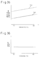
Fig. 35 is a graph (No. 1) indicating amounts of
transmission light required for white display and black
display in elation to temperatures of a ferroelectric
liquid crystal unit in accordance with the third aspect of
the present invention;
Fig. 36 is a graph (No. 1) showing a relationship of
a contrast ratio to a temperature of the ferroelectric
liquid crystal unit in accordance with the third aspect of
the present invention;
Fig. 37 is a graph (No. 2) indicating amounts of
transmission light required for white display and black
display in relation to temperatures of the ferroelectric
liquid crystal unit in accordance with the third aspect of
the invention;
Fig. 38 is a graph (No. 3) indicating amounts of
transmission light required for white display and black
display in relation to temperatures of the ferroelectric
liquid crystal unit in accordance with the third aspect of
the present invention; and
Fig. 39 is a graph (No. 2) indicating a relationship
of a contrast ration to a temperature of the ferroelectric
liquid crystal unit in accordance with the third aspect of
the present invention.
Best Mode for Carrying Out the Invention
Prior to a description of the first aspect of the
present invention, a prior art and underlying problems
will be described below.
A liquid crystal panel formed using an
antiferroelectric liquid crystal has been studied in
earnest since disclosure of, for example, Japanese
Unexamined Patent Publication No. 2-173724. The patent
publication reported that the liquid crystal panel can
provide a large angle for a field of view, can respond
fast, and can be multiplexed satisfactorily.
Fig. 2 is a diagram showing the structure of an
antiferroelectric liquid crystal panel of a liquid crystal
display having an antiferroelectric liquid crystal. A
liquid crystal panel 2 has an antiferroelectric liquid
crystal 26 sandwiched between a pair of substrates 23a and
23b. The antiferroelectric liquid crystal 26 is placed
between sheet polarizers 21a and 21b that are arranged in
the form of cross-nicol. Herein, the sheet polarizers are
arranged so that the major axis of an average molecule of
the antiferroelectric liquid crystal will be parallel to a
plane of polarization, which is produced by either of the
sheet polarizers, in the absence of an electric field.
Fig. 3 shows a relationship of an applied voltage to
be applied to the antiferroelectric liquid crystal panel
having the structure shown in Fig. 2 to an amount of
transmission light required by the antiferroelectric
liquid crystal panel at that time. The axis of ordinates
indicates an amount of transmission light, and the axis of
abscissas indicates an applied voltage. The applied
voltage is applied with the polarity thereof set to a
positive or negative polarity. As illustrated, the
antiferroelectric liquid crystal assumes three stable
states: an antiferroelectric state in which no light is
passed; a first ferroelectric state in which light is
transmitted with application of a positive voltage of a
certain value or more (+V2); and a second ferroelectric
state in which light is transmitted with application of a
negative voltage of a certain value or more (-V4).
In general, the antiferroelectric liquid crystal unit
has a backlight located on one side of the
antiferroelectric liquid crystal panel. When no voltage
is applied, the antiferroelectric liquid crystalline
molecules are placed in the antiferroelectric state. The
major axis of an average molecule is aligned with a plane
of polarization produced by a sheet polarizer. Light
emanating from the backlight will therefore not be
transmitted. Moreover, when a voltage is applied to the
antiferroelectric liquid crystal panel, the
antiferroelectric liquid crystal is, as shown in Fig. 3,
brought to the first or second ferroelectric state
according to the polarity of an applied voltage.
Accordingly, the major axis of the average molecule varies
its direction. The molecules of the antiferroelectric
liquid crystal tilt at a certain angle with respect to the
plane of polarization. The light emanating from the
backlight is therefore transmitted by the
antiferroelectric liquid crystal panel. This results in a
larger amount of transmission light.
Assume that the antiferroelectric liquid crystal
makes a transition to the first or second ferroelectric
state, and light is transmitted, that is, white display is
carried out. Especially in this case, an amount of
transmission light is, as shown in Fig. 4, determined with
an angle (referred to as a conical angle) () between a
direction M1 in which the major axis of an average
molecule of the antiferroelectric liquid crystal is
oriented in the first ferroelectric state, and a direction
M2 in which the major axis of the average molecule is
oriented in the second ferroelectric state. As the
conical angle gets larger to approach 90°, the amount of
transmission light required for white display increases.
By contrast, when the conical angle gets smaller, the
amount of transmission light required for white display
decreases.
However, the conical angle of an antiferroelectric
liquid crystalline molecule is not always constant. The
conical angle depends greatly on, for example, a use
temperature, that is, a temperature at which the
antiferroelectric liquid crystal unit is driven to become
usable for display (that is, an ambient temperature at
which the liquid crystal device is usable). In Fig. 5,
the axis of ordinates indicates a contrast ratio for
display (amount of transmission light for white display /
amount of transmission light for black display), and the
axis of abscissas indicates the use temperature. For this
graph, the temperature of use is varied within a range of
temperature of use, that is, a range from 15°C to 50°C
within which the antiferroelectric liquid crystal is
usually used. The contrast ratio for display of the
antiferroelectric liquid crystal unit is measured at each
temperature of use. As illustrated, as the temperature of
use rises, the contrast ratio for display decreases.
On the other hand, in Fig. 6, the axis of ordinates
indicates the conical angle, and the axis of abscissas
indicates the temperature of use. As illustrated, as the
temperature of use rises, the conical angle decreases.
This relationship agrees with the relationship shown in
Fig. 5. That is to say, as the temperature rises of use,
the conical angle decreases, and the tilt of the
antiferroelectric liquid crystalline molecules relative to
a plane of polarization gets smaller. Consequently, the
amount of transmission light decreases. The contrast
ratio for display of the antiferroelectric liquid crystal
unit is thus deeply temperature-dependent. This poses a
problem that the antiferroelectric liquid crystal unit
cannot achieve satisfactory display in a use environment
suffering from a great temperature change.
For example, Japanese Unexamined Patent Publication
No. 7-230079 discloses a technology of stabilizing the
temperature of use of an antiferroelectric liquid crystal
unit using a heater all the time for improving the
efficiency of response at a low temperature. However,
this technology is intended to improve the response
efficiency of the antiferroelectric liquid crystalline
molecules. Nothing is disclosed concerning the
temperature-dependency of the conical angle of the
antiferroelectric liquid crystalline molecules. Moreover,
problems concerning a contrast ratio for display and a
change in luminance have not been discussed at all.
Furthermore, as mentioned above, the Japanese Unexamined
Patent Publication No. 7-230079 is accompanied by an
increase in power consumption deriving from the use of the
heater.
According to the first aspect of the present
invention, an object of the present invention is to solve
the foregoing problems, and to provide an
antiferroelectric liquid crystal unit in which a change in
contrast ratio for display will remain small despite a
change in temperature of use, and a power consumption of a
backlight will not rise.
Prior to a description of the second aspect of the
present invention, a prior art and its underlying problems
will be described below.
In the above description, the liquid crystal 26 is an
antiferroelectric liquid crystal. According to the second
aspect of the present invention, either the
antiferroelectric liquid crystal or a ferroelectric liquid
crystal can be adopted as the liquid crystal 26.
Consequently, the term "liquid crystal" refers to either
the antiferroelectric liquid crystal or ferroelectric
liquid crystal.
The antiferroelectric liquid crystal panel shown in
Fig. 2 will be further described. A spacer used to keep
the spacing constant and the liquid crystal 26 are
sandwiched between sealing compounds 22a and 22b. A plane
of polarization produced by the first sheet polarizer 21a
and a plane of polarization produced by the second sheet
polarizer 21b lie substantially at an angle of 90°. When
a ferroelectric liquid crystal is used as a liquid
crystal, a direction in which the major axis of an average
molecule is oriented in the first or second ferroelectric
state is aligned with either the plane of polarization
produced by the first sheet polarizer 21a or second sheet
polarizer 21b.
Figs. 23a and 23b show illustratively a liquid
crystalline molecule of the liquid crystal panel 2 seen
from above. A direction in which the major axis of an
average molecule of a liquid crystal is oriented will be
described in conjunction with the drawings. For example,
assume that an electric field E is applied in a direction
from the face of she drawing (upper glass substrate of the
liquid crystal panel) to the back thereof (lower glass
substrate thereof) (Fig. 23a). When the liquid crystal is
brought to the first ferroelectric state, the major axis
of the average liquid crystalline molecule LCM tilts by an
angle "1" with an axis of orientation OA set by an
orientation film, and stays stable in a direction M2. On
the other hand, assume that an electric field E is applied
in a direction from the back of the drawing to the face
thereof (Fig. 23b). When the liquid crystal is brought to
the second ferroelectric state, the major axis of the
liquid crystalline molecule LCM tilts by an angle of "2"
clockwise relative to the axis of orientation OA, and
stays stable in a direction M2.
A liquid crystalline molecule LCM shifts along the
lateral surface of a cone defined by a segment in the
direction M of the major axis thereof. Moreover, a sum
(1+2) of the angle 1 and angle 2 refers to an angle
between the direction in which the major axis of the
average molecule of the liquid crystal is oriented in the
first ferroelectric state and the direction in which the
major axis thereof is oriented in the second ferroelectric
state, that is, a central angle (that is, a conical
angle) of a cone.
Now, a state of a ferroelectric liquid crystal in
which the major axis of an average molecule is oriented in
the direction shown in Fig. 23a is referred to as the
first ferroelectric state. A state thereof in which the
major axis of the average molecule is oriented in the
direction shorn in Fig. 23b is referred to as the second
ferroelectric stage. Moreover, even when the liquid
crystal is an antiferroelectric liquid crystal, the major
axis of the average molecule allegedly shifts over the
lateral surface of a cone. The antiferroelectric liquid
crystal assumes, as mentioned previously, an
antiferroelectric state in addition to the first
ferroelectric state and second ferroelectric state. In
the antiferroelectric state, the major axis of the average
molecule is oriented alternately in the directions shown
in Figs. 23a and 23b in the absence of an electric field.
A mean direction of all directions in which the major axis
of the average molecule is oriented is aligned with the
axis of orientation OA.
Fig. 24 shows an example of a positional relationship
between the major axis of a liquid crystalline molecule
and a plane of polarization produced by a sheet polarizer.
This example is concerned with a ferroelectric liquid
crystal. In general, when a ferroelectric liquid crystal
is employed, either of a plane of polarization P1 produced
by the first sheet polarizer and a plane of polarization
P2 produced by the second sheet polarizer is aligned with
the direction M2 in which the major axis of a molecule is
oriented in the first or second ferroelectric state (in
this example, the direction M2 is aligned with the plane
of polarization P1). In this case, the plane of
polarization P1 produced by the first sheet polarizer and
the plane of polarization P2 produced by the second sheet
polarizer lie at an angle of substantially 90°. This
arrangement leads to a minimum amount of transmission
light required for dark display. When the orientation of
an electric field E is reversed, a liquid crystalline
molecule LCM moves with the axis of orientation OA as an
axis of symmetry. This results in a maximum amount of
transmission light.
Problems underlying a prior art will be described in
conjunction with Figs. 25, 26, and 27. Conventionally,
the first sheet polarizer and second sheet polarizer are
fixed to glass substrates using an adhesive or the like.
However, a temperature observed when the sheet polarizers
of a liquid crystal unit are assembled or a temperature
observed when an angle at which the sheet polarizers are
bonded is determined may be different from a temperature
at the time of use. In this case, an angle between the
direction M2 of the major axis of a liquid crystalline
molecule LCM and the axis of orientation OA (angle 1 or
2) changes. The direction M2 in which the major axis of
a molecule is, as shown in Fig. 25, aligned with the plane
of polarization P1 produced by the sheet polarizer. In
the words, since the conical angle of a liquid
crystalline molecule varies depending on a temperature of
use, the plane of polarization produced by the sheet
polarizer that has just been placed and the direction in
which the major axis of the molecule is oriented are
misaligned mutually.
In Fig. 26, the axis of ordinates indicates an amount
of transmission light, and the axis of abscissas indicates
a temperature of use. This graph is concerned with a
sheet polarizer bonded to a glass substrate so that the
direction M2 in which the major axis of a liquid
crystalline molecule LCM is oriented in the first
ferroelectric state will be aligned with the plane of
polarization P1 produced by the sheet polarizer. As seen
from the graph, the amount of transmission light required
for dark display at a temperature falling within a range
of temperature of use varies greatly. An amount of
transmission light observed at a temperature of use of
40°C is a minimum value. Fig. 27 indicates a ratio of an
amount of transmission light required for white display to
an amount of transmission light required for black display
as a contrast ratio for display. A change in temperature
is reversed at 40°. This leads to a decrease in contrast
ratio for display. The above description is concerned
with a ferroelectric liquid crystal. The same applies to
an antiferroelectric liquid crystal.
According to the second aspect of the present
invention, an object of the present invention is to
provide a liquid crystal unit capable of offering a
maximum contrast ratio even when a conical angle of a
liquid crystalline molecule varies with a change in
temperature occurring at a temperature that falls within a
range of temperatures of use.
Prior to a description of the third aspect of the
present invention, a prior art and underlying problems
will be described below.
As mentioned above, a ferroelectric liquid crystal is
generally known as a liquid crystal that assumes first and
second ferroelectric states. A ferroelectric liquid
crystal panel having the ferroelectric liquid crystal has
been studied in earnest since it was revealed by Clerk et
al. in U.S. Patent No. 4367924. The report reads that
the ferroelectric liquid crystal panel exerts a memory
effect and responds at a high speed, and the ferroelectric
liquid crystal panel can be multiplexed satisfactorily.
A liquid crystalline molecule of a ferroelectric
liquid crystal moves, as mentioned previously, over the
lateral surface of a cone according to a change in applied
electric field. In other words, a ferroelectric liquid
crystalline molecule is switched from one state to another
or moved over the lateral surface only when a given
pulsating wave is applied to the liquid crystalline
molecule. At this time, a product of the pulse duration
of the pulsating wave by a voltage is equal to or larger
than a threshold voltage. When an applied voltage has an
opposite polarity, the first or second of the two
ferroelectric states is selected.
In Fig. 31, a ferroelectric liquid crystal is adopted
as a liquid crystal. As already described in conjunction
with Figs. 24 and 25, sheet polarizers are arranged so
that the direction M2 in which the major axis of an
average molecule of the liquid crystal is oriented in the
second ferroelectric state will be aligned with the plane
of polarization P produced by one of the sheet polarizers.
When liquid crystal molecules are brought to the second
ferroelectric state, transmission light does not pass
through a liquid crystal panel. The liquid crystal panel
therefore appears in black. When the liquid crystalline
molecules are brought to the first ferroelectric state M1,
transmission light passes. The panel therefore appears in
white.
However, as mentioned previously, a conical angle ()
defined between a direction in which the major axis of an
average molecule of a liquid crystal is oriented in the
first ferroelectric state and a direction in which the
major axis thereof is oriented in the second ferroelectric
state changes with a temperature. A temperature of use of
a liquid crystal panel is not always constant.
Consequently, the direction in which the major axis of the
average molecule of the liquid crystal is oriented in the
first or second ferroelectric state changes with the
temperature of use. An amount of transmission light
required by a liquid crystal panel having a ferroelectric
liquid crystal changes with the use temperature
irrespective of whether white display or black display is
under way. This poses a problem that a contrast ratio for
display that is a ratio of an amount of transmission light
for white display to an amount of transmission light for
black display changes with the use temperature.
For example, assume that the temperature of use has a
maximum value. The direction in which the major axis of
an average molecule of a ferroelectric liquid crystal is
oriented in one of the two ferroelectric states is aligned
with a plane of polarization produced by one sheet
polarizer. That is to say, sheet polarizers are arranged
so that a state shown in Fig. 31 will be established.
Thereafter, when the temperature of use decreases, the
conical angle becomes smaller. The direction in which the
major axis of an average molecule of a ferroelectric
liquid crystal is oriented changes from the direction
shown in Fig. 31 to the one shown in Fig. 32. Fig. 33
graphically shows the results of measuring an amount of
transmission light required for white display and an
amount of transmission light required for black display at
a temperature falling within a range of temperature of use
(T1 denotes a minimum temperature of use, and T2 denotes a
maximum use temperature). As shown in Fig. 33, the amount
of transmission light for black display (e) increases
(solid line) with a drop in temperature of use. The
amount of transmission light for white display (f)
decreases (dashed line) with a drop in temperature of use.
The contrast ratio for display therefore varies depending
on the temperature of use as shown in Fig. 32. When this
ferroelectric liquid crystal panel is used for display,
the contrast ratio varies depending on the temperature of
use. This poses a problem of impaired display quality.
Problems underlying the Japanese Unexamined Patent
Publication No. 7-230079 are identical to those
accompanying the first aspect of the present invention,
and also underlie the third aspect thereof. The
literature neither refers to the temperature-dependency of
the conical angle nor discusses a problem on a change in
contrast ratio or luminance. Moreover, like the first
aspect, there are a problem on use of a heater, a problem
on properties to be maintained at a low temperature, and a
problem on an increase in power consumption at a high
temperature.
According to the third aspect of the present
invention, an object of the present invention is to
provide a ferroelectric liquid crystal unit in which even
when a temperature of use of a liquid crystal panel having
a ferroelectric liquid crystal changes, a change in
contrast ratio for display will be limited, and in which a
power consumption required by a backlight will not
increase.
The present invention will be described below.
To begin with, embodiments of the first aspect of the
present invention will be described below.
As mentioned previously, when an antiferroelectric
liquid crystal panel having the structure shown in Fig. 2
appears in white, an amount of transmission light depends
on a conical angle of a ferroelectric liquid crystal
molecule. A maximum value of the conical angle is
substantially 90°. As the conical angle decreases, the
amount of transmission light decreases. However, when the
panel appears in black, the amount of transmission light
remains constant but does not depend on the conical angle.
Ideally, the amount of transmission light is zero.
Consequently, when the conical angle is held constant, the
amount of light transmitted for white display is held
constant all the time. High-quality display is enabled.
The conical angle depends on a temperature. For
example, when an antiferroelectric liquid crystal is
heated, the antiferroelectric liquid crystal makes a
transition to an SmA phase depending on the ferroelectric
liquid crystal phase or material thereof. At a transition
temperature or a temperature at which the ferroelectric
liquid crystal phase or SmA phase appears, the conical
angle is minimized. As the temperature gets lower than
the transition temperature, the conical angle increases.
The amount of transmission light for white display gets
smaller with a higher temperature. As the temperature
recedes from the transition temperature or gets lower, the
amount of transmission light for white display increases.
A contrast ratio for display permitted by an
antiferroelectric liquid crystal unit used for display is
a ratio of an amount of transmission light for white
display to an amount of transmission light for black
display. The contrast ratio therefore changes with a
change in amount of transmission light for white display.
To be more specific, when the temperature of an
antiferroelectric liquid crystal is equal to the
transition temperature, the contrast ratio for display has
a minimum value. As the temperature of the
antiferroelectric liquid crystal changes from the
transition temperature to a lower temperature, the
contrast ratio for display increases.
A change in contrast ratio for display is a change in
amount of transmission light for white. A change in
contrast ratio for display can therefor be avoided by
compensating for the magnitude of the change. The amount
of transmission light for white can be adjusted by varying
an amount of light that falls on an antiferroelectric
liquid crystal panel and is output from a backlight. In a
antiferroelectric liquid crystal panel having the
structure shown in Fig. 2, sheet polarizers are arranged
so that planes of polarization produced thereby will lie
at an angle of substantially 90°, and the plane of
polarization produced by one of the sheet polarizers will
be aligned with the direction in which the major axis of
an average molecule of an antiferroelectric liquid crystal
is oriented in an antiferroelectric state. When an amount
of light output from the backlight is maximized at an
uppermost temperature of use, a change in contrast ratio
for display dependent on a temperature can be prevented.
When the amount of light output from the backlight is
minimized at a lowermost temperature of use, the change in
contrast ratio for display dependent on a temperature can
be prevented.
Moreover, an antiferroelectric liquid crystal
possesses a spontaneous polarization. When
antiferroelectric liquid crystalline molecules are
reversed from a ferroelectric state to an
antiferroelectric state or vice versa, a polarization
reverse current flows. The polarization reverse current
is directly proportional to the magnitude of the
spontaneous polarization. The spontaneous polarization of
the antiferroelectric liquid crystal varies, as shown in
Fig. 7, depending on a change in use temperature. In Fig.
7, the axis of ordinates indicates the spontaneous
polarization, and the axis of abscissas indicates the use
temperature.
The spontaneous polarization can be estimated based
on the polarization reverse current flowing through pixels
in a liquid crystal. The temperature of an
antiferroelectric liquid crystal panel may not be actually
measured. As long as the polarization reverse current can
be measured, the temperature of the antiferroelectric
liquid crystal panel can be estimated. The magnitude of a
change in conical angle can be calculated. Consequently,
an amount of light output from a backlight can be adjusted
based on a change in polarization reverse current. An
electrode on which a polarization reverse current is
measured is formed on a substrate according to the same
procedure as a procedure of forming electrodes used as
pixels. This facilitates measuring of the polarization
reverse current.
A transmission light sensor may be included for
measuring a luminance level of transmission light output
from the backlight and passed through the
antiferroelectric liquid crystal panel. Besides, a memory
may be included for storing a correlation between a
conical angle and a luminance level of transmission light.
In this case, an amount of light output from the backlight
can be adjusted without the necessity of measuring the
temperature of the antiferroelectric liquid crystal panel
or a polarization reverse current. In other words, before
the antiferroelectric liquid crystal panel is actually
activated, a correlation between a luminance level
detected by the transmission light sensor and a conical
angle of an antiferroelectric liquid crystalline molecule
is checked. The correlation is stored in the memory.
When display is carried out actually, the amount of light
output from the backlight is adjusted based on the
luminance level detected by the transmission light sensor
and the correlation stored in the memory. Light is then
re-output from the backlight.
An embodiment of the first aspect will be described
in conjunction with the drawings. Fig. 2 is a diagram
showing the structure of an antiferroelectric liquid
crystal panel 2 of this embodiment. The antiferroelectric
liquid crystal panel 2 of this embodiment is composed of a
pair of glass substrates 23a and 23b having an
antiferroelectric liquid crystal layer 26 approximately 2
µm thick between them. Display electrodes 24a and 24b are
formed on opposed surfaces of the glass substrates.
Orientation films 25a and 25b are applied over the display
electrodes, and rubbed. A first sheet polarizer 21a is
placed on the outer surface of one glass substrate 23a so
that a plane of polarization produced by the sheet
polarizer will be parallel to a direction in which the
major axis of an antiferroelectric liquid crystalline
molecule is oriented in the first ferroelectric state. A
second sheet polarizer 21b is placed on the outer surface
of the other glass substrate 23b so that a plane of
polarization produced by the second sheet polarizer 21b
will be deviated by substantially 90° from the plane of
polarization produced by the first sheet polarizer 21a.
Fig. 6 is a graph indicating a relationship between a
use temperature of an antiferroelectric liquid crystal of
this embodiment and a conical angle of a molecule thereof.
Fig. 6 demonstrates that the conical angle of a molecule
of the antiferroelectric liquid crystal gets smaller with
an increase in use temperature.
A graph shown in Fig. 8 represents relationships of
an amount of transmission light for white display (b) and
an amount of transmission light for black display (a) to a
temperature of use or a temperature at which a
conventional antiferroelectric liquid crystal unit having
an antiferroelectric liquid crystal is used. In the
conventional antiferroelectric liquid crystal unit, the
antiferroelectric liquid crystal panel shown in Fig. 2 is
provided with a backlight alone. An amount of light
emanating from the backlight is not controlled. The
amount of transmission light for white display decreases,
as shown in Fig. 8b, with a rise in temperature.
However, the amount of transmission light for black
display hardly changes as shown in Fig. 8a. A contrast
ratio (amount of transmission light for white display /
amount of transmission light for black display) decreases
with a rise in use temperature.
Fig. 1 is a diagram schematically showing an
antiferroelectric liquid crystal unit of an embodiment of
the first aspect and an amount-of-output light control
unit connected to a backlight. A liquid crystal unit 10
has an antiferroelectric liquid crystal panel 2 having the
structure shown in Fig. 2 and a backlight 1. Moreover, a
temperature sensor 3 is placed on a glass substrate. The
backlight 1 and temperature sensor 3 are electrically
coupled and interlocked with each other via the amount-of-output
light control unit 4.
In Fig. 9, the ordinate indicates an amount of light
output from the backlight, and the abscissa indicates a
temperature of use. In Fig. 10, the ordinate indicates an
amount of transmission light and the abscissa indicates
the temperature of use. The antiferroelectric liquid
crystal unit 10 having the structure shown in Fig. 1
carries out display, and the temperature sensor 3 samples
a temperature of use. The amount of light output from the
backlight is, as shown in Fig. 9, increased with a rise in
temperature of use.
Fig. 10 indicates the results of measuring an amount
of transmission light for white display (d) (dashed line)
and an amount of transmission light for black display (c)
(solid line) in relation to a change in temperature
occurring in the antiferroelectric liquid crystal unit 10
having the structure shown in Fig. 1. As illustrated, the
amount of transmission light for white display (d) does
not depend on the temperature of use and remains
substantially constant. This means that a change in
contrast ratio for display dependent on a temperature is
resolved substantially.
Fig. 11 is a diagram showing schematically an
antiferroelectric liquid crystal unit of another
embodiment of the first aspect of the present invention,
and an amount-of-output light control unit connected to a
backlight. A liquid crystal unit 10 has an
antiferroelectric liquid crystal panel 2 having the
structure shown in Fig. 2, and a backlight 1. An
electrode 40b is placed on a glass substrate. The
electrode 40b is made of the same material as the material
of display electrodes, and produced according to the same
process as the process for producing the display
electrodes. The electrode 40b is used to measure a
polarization reverse current. As illustrated, the
backlight 1 and electrode 40b are electrically coupled and
interlocked with each other via the amount-of-output light
control unit 4.
The antiferroelectric liquid crystal unit having the
structure shown in Fig. 11 carries out display, and the
electrode 40b is used to measure a polarization reverse
current. An amount of light output from the backlight is
varied by the amount-of-output light control unit 4
according to a polarization reverse current. When the
polarization reverse current gets larger, the amount of
light output from the backlight is decreased. When the
polarization reverse current gets smaller, the amount of
light output from the backlight is increased. The amounts
of transmission light required for white display and black
display by the antiferroelectric liquid crystal unit 10
having the structure shown in Fig. 11 were measured in
relation to a change in temperature. The results of the
measurement demonstrate that the amount of transmission
light for white display does not depend on the temperature
of use but remains substantially constant. This means
that a change in contrast ratio dependent on a temperature
is resolved substantially.
Fig. 12 is a diagram schematically showing an
antiferroelectric liquid crystal unit of yet another
embodiment of the first aspect, and an amount-of-output
light control unit connected to a backlight. A liquid
crystal unit 10 has an antiferroelectric liquid crystal
panel 2 having the structure shown in Fig. 2, and a
backlight 1. A transmission light sensor 30c for
measuring a luminance level of transmission light having
output from the backlight and passed through an
antiferroelectric liquid crystal panel is placed on a
glass substrate. As illustrated, the backlight 1 and
transmission sensor 30c are electrically coupled and
interlocked with each other via the amount-of-output light
control unit 4. Moreover, the liquid crystal unit 10 is
provided with a memory 5 for storing a correlation between
a conical angle of an antiferroelectric liquid crystalline
molecule and a luminance level of transmission light.
Based on the luminance level measured by the transmission
light sensor 30c and the correlation stored in the memory,
the amount of light output from the backlight is adjusted
and light is re-output therefrom.
The amounts of transmission light required for white
display and black display by the antiferroelectric liquid
crystal unit 10 having the structure shown in Fig. 12 were
measured in relation to a change in temperature. The
results of the measurement demonstrate that the amount of
transmission light for white display does not depend on a
temperature of use but remains substantially constant.
This means that a change in contrast ratio for display
dependent on a temperature is substantially resolved.
Next, embodiments of the second aspect will be
described below.
Fig. 13 is a sectional view of a liquid crystal unit
in accordance with the second aspect. Fig. 14 is an
overall exploded view. Figs. 15a and 15b are plan views
of a liquid crystal display that is seen from above. The
liquid crystal panel 2 shown in Fig. 2 is used as a liquid
crystal unit 10. The liquid crystal panel 2 has glass
substrates, on which display electrodes and orientation
films are formed, arranged so that the orientation films
will be opposed to each other. A liquid crystal is
clamped using a sealing compound. Conventionally, sheet
polarizers are fixed to substrates using an adhesive or
the like. According to the second aspect, as shown in
Fig. 13, a first sheet polarizer 21a and second sheet
polarizer 21b that are not fixed to the liquid crystal
panel 2 are placed outside the glass substrates. The
first and second sheet polarizers share the same axis of
rotation 50a. As shown in Fig. 14, a drive circuit 70 for
inputting a driving wave is constructed by connecting a
flexible printed-circuit (FPC) board 80 to the liquid
crystal panel 2 of the liquid crystal display.
As shown in Figs. 15a and 15b, the sheet polarizers
21a and 21b can be turned arbitrarily with an axis-of-rotation
hole 21d, into which the axis of rotation 50 is
inserted, as a center. By thus adjusting the sheet
polarizers, both or either of planes of polarization
produced by the first sheet polarizer 21a and second sheet
polarizer 21b is aligned with the major axis of an average
molecule of a liquid crystal irrespective of whether the
liquid crystal is brought to the first ferroelectric state
or second ferroelectric state.
To be more specific, as a structure used for
adjustment, as shown in Fig. 15a, a sheet polarizer
turning dial 60 to be turned may be adopted.
Alternatively, as shown in Fig. 15b, a sheet polarizer
turning lever 21c to be moved may be adopted. The sheet
polarizer is shaped so that the effective display portion
of a glass substrate or liquid crystal panel 2 will not
come out after the sheet polarizer is turned. The shape
of the sheet polarizer may be a rectangle or sector.
Moreover, the plane of polarization P1 produced by the
first sheet polarizer 21a and the plane of polarization P2
produced by the second sheet polarizer 21b are fixed at an
angle of 90°.
In Figs. 16a and 16b, the angle of the first sheet
polarizer 21a relative to the liquid crystal panel 2 is
adjusted. The sheet polarizer turning lever 21 is moved
up and down (See an arrow). The first sheet polarizer 21a
and second sheet polarizer 21b located as indicated with
an alternate long and two short dashes line are then
positioned as indicated with a solid line. The plane of
polarization P1 produced by the first sheet polarizer 21a
and the plane of polarization P2 produced by the second
sheet polarizer 21b can thus be tilted relative to the
major axis of an average molecule of a liquid crystal
staying in the first or second ferroelectric state.
As a method of turning the sheet polarizer, a method
of manually turning them by moving the sheet polarizer
turning dial 60 or sheet polarizer turning lever 21c has
been described in conjunction with Figs. 15a and 15b.
Another method is a method in which a micro stepper motor
50 is, as shown in Fig. 19, used as a turning control unit
and engaged with an axis of rotation 50a. In this case,
the micro stepper motor 50 is engaged with the axis of
rotation 50a, and used to turn both sheet polarizers
according to a change in conical angle of a liquid
crystalline molecule. The sheet polarizers are located at
an angle of substantially 90°. Planes of polarization
produced by the sheet polarizers are aligned with each
other so that an amount of transmission light required for
dark display will be minimized.
Embodiments of the second aspect will be described in
conjunction with the drawings. Fig. 20 is a diagram
showing the structure of a liquid crystal panel of this
embodiment, that is, the liquid crystal panel 2 shown in
Fig. 2. A temperature sensor 30b is placed on a glass
substrate. A stepper motor 50 serving as a control unit
for controlling turning of the sheet polarizers 21a and
21b is engaged with an axis of rotation. The stepper
motor 50 and temperature sensor 30b are electrically
coupled and interlocked with each other.
The liquid crystal unit having the structure shown in
Fig. 20 is used to carry out display. The temperature
sensor 30b is used to sample a temperature of use. An
angle of rotation by which the sheet polarizers are turned
is varied depending on a temperature by means of the
stepper motor 50. Fig. 17 shows the results of measuring
an amount of transmission light required for dark display
in relation to a change in temperature, wherein the liquid
crystal unit shown in Fig. 20 is taken for instance. As
illustrated, an amount of transmission light for dark
display does not depend on a temperature but remains
substantially constant. As shown in Fig. 18, a change in
contrast ratio for display dependent on a temperature is
reduced.
Fig. 21 is a diagram showing a structure of another
embodiment of the second aspect. A stepper motor 50 is
engaged with an axis of rotation 50a. An electrode 40a is
placed on a glass substrate. The electrode 40a is made of
the same material as display electrodes and produced
according to the same process as they are produced. The
axis of rotation 50a and electrode 40a are electrically
coupled and interlocked with each other via the stepper
motor 50.
The liquid crystal unit having the structure shown in
Fig. 21 is used for display. The electrode 40a is used to
measure a polarization reverse current. An angle of
rotation by which the sheet polarizers are turned is
varied depending on a polarization reverse current. The
amounts of transmission light required by the liquid
crystal unit having the structure shown in Fig. 21 were
measured. The results of the measurement demonstrate that
the amount of transmission light for dark display does not
depend on a temperature but remains substantially
constant. A change in contrast ratio for display
dependent on a temperature is resolved substantially.
Fig. 22 is a diagram showing yet another embodiment
of the second aspect of the present invention. A stepper
motor 50 is engaged with an axis of rotation 50a. A
transmission light sensor 30a for measuring an amount of
transmission light, which has passed through a liquid
crystal panel, is placed on a glass substrate. The axis
of rotation 50a and light transmission sensor 30a are
electrically coupled and interlocked with each other via
the stepper motor 50.
In the liquid crystal unit having the structure shown
in Fig. 22, an angle of rotation by which the sheet
polarizers are turned is varied depending on a change in
amount of transmission light for dark display, which is
detected by the transmission light sensor 30a, by means of
the stepper motor. In the liquid crystal unit having the
structure shown in Fig. 22, the amount of transmission
light for dark display does not depend on a temperature of
use but remains substantially constant. A change in
contrast ratio for display dependent on a temperature is
resolved.
In the liquid crystal unit according to the second
aspect, the major axis of an average molecule of a liquid
crystal staying in a ferroelectric state is always aligned
with a plane of polarization produced by either of the
sheet polarizers. This means that a transmittance of
light for dark display remains almost constant
irrespective of a temperature. Consequently, a contrast
ratio for display that is a ratio of an amount of
transmission light for dark display to an amount of
transmission light for bright display can always be set to
a high value.
Embodiments of the third aspect of the present
invention will be described below.
According to the third aspect of the present
invention, a liquid crystal panel has a liquid crystal,
which assumes at least first and second ferroelectric
states, sandwiched between a pair of substrates. First
and second sheet polarizers are placed to interpose the
pair of substrates between them. A plane of polarization
produced by the first sheet polarizer and a plane of
polarization produced by the second sheet polarizer are
fixed at an angle of substantially 90°.
Two planes are defined at angles that are halves of
angles defined by the plane of polarization produced by
the first sheet polarizer and the plane of polarization
produced by the second sheet polarizer. One of the planes
is regarded as a first intermediate plane, and the other
is regarded as a second intermediate plane.
The sheet polarizers are arranged so that: a
direction in which the major axis of an average molecule
of a ferroelectric liquid crystal is oriented in one of
the first and second ferroelectric states will always be
located between the plane of polarization produced by the
second sheet polarizer and the first intermediate plane at
a temperature falling within a use temperature range
within which the ferroelectric liquid crystal panel is
usable; and a direction in which the major axis of the
average molecule of the ferroelectric liquid crystal is
oriented in the other ferroelectric state will always be
located between the plane of polarization produced by the
first sheet polarizer and the first intermediate plane.
Alternatively, the sheet polarizers are arranged so
that: a direction in which the major axis of the average
molecule of the ferroelectric liquid crystal is oriented
in one ferroelectric state will always be located between
the plane of polarization produced by the second sheet
polarizer and the second intermediate plane; and a
direction in which the major axis of the average molecule
of the ferroelectric liquid crystal is oriented in the
other ferroelectric state will always be located between
the plane of polarization produced by the second sheet
polarizer and the first intermediate plane.
Alternatively, the sheet polarizers are arranged so
that: a direction in which the major axis of the average
molecule of the ferroelectric liquid crystal is oriented
in one ferroelectric state will always be located between
the plane of polarization produced by the first sheet
polarizer and the first intermediate plane; and a
direction in which the major axis of the average molecule
of the ferroelectric liquid crystal is oriented in the
other ferroelectric state will always be located between
the plane of polarization produced by the first sheet
polarizer and the second intermediate plane.
A curve indicating a change in amount of transmission
light relative to a change in conical angle, which occurs
at a temperature falling within a use temperature range
within which the ferroelectric liquid crystal panel
achieves white display, has neither a maximal value nor
minimal value. In short, the change curve exhibits a
monotonous decrease or monotonous increase. Moreover, a
curve indicating a change in amount of transmission light
relative to a change in temperature, which occurs at a
temperature within a range of temperature of use within
which black display is achieved, has neither a maximal
value nor a minimal value. In short, the change curve
exhibits a monotonous decrease or a monotonous increase.
Furthermore, a differential coefficient of a function
represented by a curve indicating a change in amount of
transmission light due to a change in conical angle, which
occurs at a temperature within a range of temperature of
use within which white display is achieved, has the same
property as a differential coefficient of a function
represented by a curve indicating a change in amount of
transmission light due to a change in temperature of use
which occurs at a temperature within a temperature of use
range within which black display is achieved.
A contrast ratio for display is a ratio of an amount
of transmission light required for white display to an
amount of transmission light required for black display.
Even if the amount of transmission light for white display
decreases depending on a temperature of use, since the
amount of transmission light for black display decreases,
a change in contrast ratio for display will be
substantially resolved. Moreover, even when the amount of
transmission light for white display increases, the amount
of transmission light for black display increases. The
same effect can be exerted.
Furthermore, when a ferroelectric liquid crystal unit
is provided with a backlight, an amount of light output
from the backlight is varied depending on a conical angle
of a ferroelectric liquid crystalline molecule. A
function represented by a curve indicating a change in
amount of light output from the backlight is determined so
that a differential coefficient of the function will
exhibit a property opposite to the property of a
differential coefficient of a function represented by a
curve indicating a change in amount of transmission light
for white display or black display. Specifically, when
the amounts of transmission light required for white
display and black display increase, the amount of light
output from the backlight is decreased. When the amounts
of transmission light for white display and black display
decrease, the amount of light output from the backlight is
increased. Thus, a contrast ratio for display can be kept
constant and at a better value.
As described previously, a conical angle of a liquid
crystalline molecule changes according to a use
temperature. A temperature sensor is placed on a
substrate of a ferroelectric liquid crystal panel in order
to measure the temperature of liquid crystalline
molecules. The temperature sensor and backlight are
electrically coupled and interlocked with each other. An
amount of light output from the backlight may thus be
adjusted.
Moreover, as mentioned above, a conical angle of a
liquid crystalline molecule can be calculated by measuring
a polarization reverse current instead of a use
temperature. In general, when a ferroelectric liquid
crystal is switched from one ferroelectric state to the
other ferroelectric state, a spontaneous polarization is
reversed. This causes, as already known, a reverse
current to flow through a liquid crystal panel. The level
of the polarization reverse current is directly
proportional to the magnitude of the spontaneous
polarization. The magnitude of the spontaneous
polarization changes with a temperature. A change in
temperature can therefore be calculated by calculating a
change in polarization reverse current. In other words, a
change in conical angle of a liquid crystalline molecule
can be worked out by checking the change in polarization
reverse current. For measuring the polarization reverse
current, another electrode different from electrodes
forming pixels may be included. In this case, a change in
polarization reverse current is checked, and the electrode
and backlight are electrically coupled and interlocked
with each other. An amount of light output from the
backlight is thus varied.
Alternatively, inclusion of a transmission sensor is
conceivable. In this case, a luminance level of
transmission light transmitted by a liquid crystal panel
is measured using a photodiode or the like. A luminance
level permitted by a backlight is varied depending on a
change in amount of transmission light.
Embodiments of the third aspect of the present
invention will be described in conjunction with the
drawings. In the embodiments, the liquid crystal panel 2
shown in Fig. 2 can be used as it is. The structure shown
in Fig. 2 has already been described and a reiteration
will be omitted. For a better understanding, planes named
as intermediate planes are located at angles that are
halves of angles defined by a plane of polarization
produced by a first sheet polarizer and a plane of
polarization produced by a second sheet polarizer. Since
two intermediate planes exist, one of the two intermediate
planes is regarded as a first intermediate plane, and the
other is regarded as a second intermediate plane.
In one embodiment, as shown in Fig. 28, sheet
polarizers are arranged so that: a direction in which the
major axis of an average molecule of a light crystal is
oriented in one ferroelectric state will always be located
between a plane of polarization produced by the second
sheet polarizer and the first intermediate plane; and a
direction in which the major axis of the average molecule
of the liquid crystal is oriented in the other
ferroelectric state will always be located between the
first sheet polarizer and first intermediate plane. This
embodiment will be described by taking a ferroelectric
liquid crystal as a liquid crystal, though this embodiment
can be adapted to an antiferroelectric liquid crystal
alike.
A minimum use temperature or a minimum temperature at
which a ferroelectric liquid crystal unit is usable is
10°C, and a maximum use temperature is 40°C. What is
referred to as a range of temperature of use is a range
from 10°C to 40°C or the minimum use temperature to
maximum temperature of use. As described in conjunction
with Fig. 6, a temperature of use of a ferroelectric
liquid crystal and a conical angle have such a
relationship that the conical angle of a ferroelectric
liquid crystalline molecule gets smaller with a rise in
temperature.
Fig. 35 is a graph indicating relationships of an
amount of transmission light for white display (h) and an
amount of transmission light for black display (g) to a
temperature of use. Herein, the liquid crystal unit of
this embodiment having the ferroelectric liquid crystal
carries out display. As the temperature of use rises, the
amounts of transmission light increase. A contrast ratio
for display, that is, a ratio of the amount of
transmission light for white display to the amount of
transmission light for black display does not depend on
the temperature of use as seen from Fig. 36. The contrast
ratio for display remains constant and a satisfactory
display state can be realized.
Furthermore, an amount of light output from a
backlight is adjusted. The structure shown in Fig. 1 can
be employed in a liquid crystal unit of the third aspect
of the present invention. As mentioned previously, the
liquid crystal unit comprises a liquid crystal panel 2
having the structure shown in Fig. 2 and a backlight 1. A
temperature sensor 3 is placed on a glass substrate. The
backlight 1 and temperature sensor 3 are electrically
coupled and interlocked with each other via an amount-of-output
light control unit 4.
The liquid crystal unit having the structure shown in
Fig. 1 carries out display, and the temperature sensor 3
samples a temperature of use. The output control unit
varies an amount of light output from the backlight for
each temperature. The amount of light output from the
backlight is increased as the temperature of use drops.
Fig 37 indicates the results of measuring an amount of
transmission light for white display (j) and an amount of
transmission light for black display (i) relative to a
change in temperature of the ferroelectric liquid crystal
unit. Note that the amount of light output from the
backlight in the ferroelectric liquid crystal unit has
been adjusted. As shown in Fig. 37, the amounts of
transmission light for white display and black display do
not depend on the temperature of use but remain
substantially constant. Compared with the graph in Fig.
35 indicating amounts of transmission light required when
an amount of light output from a backlight is not
adjusted, a better display quality can be realized.
The structure shown in Fig. 11 can be adapted to the
liquid crystal unit of this embodiment. As mentioned
above, a ferroelectric liquid crystal panel 2 having the
structure shown in Fig. 2 is provided with a backlight 1.
An electrode 40b is placed on a glass substrate. The
electrode 40b is made of the same material as display
electrodes, and produced according to a similar process.
The backlight 1 and electrode 40b are electrically coupled
and interlocked with each other via an amount-of-output
light control unit 4.
The ferroelectric liquid crystal unit having the
structure shown in Fig. 11 carries out display, and the
electrode 40b is used to measure a polarization reverse
current. The output control unit varies an amount of
light output from the backlight according to a
polarization reverse current. When the polarization
reverse current gets larger, the amount of light output
from the backlight is increased. When the polarization
reverse current gets smaller, the amount of light output
from the backlight is decreased. The amounts of
transmission light required for white display and black
display by the ferroelectric liquid crystal panel having
the structure shown in Fig. 11 were measured in relation
to a change in temperature. The results of the
measurement are the same as the results graphically shown
in Fig. 37. That is to say, the amounts of transmission
light do not depend on the temperature of use but remain
substantially constant. A difference in contrast ratio
for display between temperatures is substantially
resolved. Satisfactory display quality is realized.
The structure shown in Fig. 12 can be employed in
this embodiment. Specifically, a ferroelectric liquid
crystal panel 2 having the structure shown in Fig. 2 is
provided with a backlight 1. A transmission light sensor
30c for measuring a luminance level of transmission light
that has been output from the backlight and passed through
the ferroelectric liquid crystal panel is placed on a
glass substrate. The backlight 1 and transmission light
sensor 30c are electrically coupled and interlocked with
each other via an amount-of-output light control unit 4.
Moreover, the liquid crystal unit is provided with a
memory 5 for storing a correlation between a conical angle
of a ferroelectric liquid crystalline molecule and a
luminance level of transmission light. Based on the
luminance level measured by the transmission light sensor
30c and the correlation stored in the memory 5, an amount
of light output from the backlight is adjusted and light
is re-output therefrom.
The amounts of transmission light required for white
display and black display by the ferroelectric liquid
crystal unit having the structure shown in Fig. 12 were
measured in relation to a change in temperature. The
results of the measurement are identical to those
graphically shown in Fig. 37. Namely, the amounts of
transmission light do not depend on the temperature of use
but remain substantially constant. A difference in
contrast ratio for display between temperatures is
substantially resolved, and satisfactory display quality
is realized.
According to another embodiment, sheet polarizers are
arranged so that: a direction in which the major axis of
an average molecule of a ferroelectric liquid crystal is
oriented in one ferroelectric state will always be located
between a plane of polarization produced by a second sheet
polarizer and a second intermediate plane; and a direction
in which the major axis of the average molecule of the
ferroelectric liquid crystal is oriented in the other
ferroelectric state will always be located between the
second sheet polarizer and a first intermediate plane.
Alternatively, the sheet polarizers are, as shown in
Fig. 30, arranged so that: a direction in which the major
axis of the average molecule of the ferroelectric liquid
crystal is oriented in one ferroelectric state will always
be located between the plane of polarization produced by
the first sheet polarizer and the first intermediate
plane; and a direction in which the major axis of the
average molecule of the ferroelectric liquid crystal is
oriented in the other ferroelectric state will always be
located between the first sheet polarizer and the second
intermediate plane. A minimum temperature of use or a
minimum temperature at which the ferroelectric liquid
crystal panel of this embodiment can be usable is 10°C,
and a maximum temperature of use thereof is 40°C. What is
referred to as a use temperature range is a range from the
minimum temperature of use to the maximum temperature of
use.
The ferroelectric liquid crystal employed in this
embodiment is made of the same material as the one in the
previous embodiment. A conical angle of a ferroelectric
liquid crystalline molecule gets smaller with a rise in
temperature.
Fig. 38 is a graph indicating relationships of an
amount of transmission light for white display (l) and an
amount of transmission light for black display (k) to a
temperature of use. Herein, the ferroelectric liquid
crystal panel of this embodiment having the above
ferroelectric liquid crystal is used for display. As the
use temperature rises, the amounts of transmission light
drop. A contrast ratio for display, that is, a ratio of
the amount of transmission light for white display to the
amount of transmission light for black display does not,
as shown in Fig. 39, depend on the temperature of use.
The contrast ratio for display remains constant, and a
satisfactory display state can be realized.
Moreover, an amount of light output from the
backlight is adjusted. Like the aforesaid embodiment, a
ferroelectric liquid crystal unit having the structure
shown in Fig. 1 is adopted. The ferroelectric liquid
crystal unit having the structure shown in Fig. 1 carries
out display and the temperature sensor 3 samples a
temperature of use. The output control unit 4 varies an
amount of light output from the backlight according to
each temperature. The amount of light output from the
backlight is increased with a rise in temperature of use.
After the amount of light output from the backlight was
adjusted, the amounts of transmission light required for
white display and black display by a ferroelectric liquid
crystal panel were measured in relation to a change in
temperature. The results of the measurement are
identical to those graphically shown in Fig. 37. As shown
in Fig. 37, the amounts of transmission light for white
display and black display do not depend on the temperature
of use but remain substantially constant. Compared with
the results of a measurement shown in Fig. 38 for which
the amount of light output from the backlight has not been
adjusted, the results of the measurement shown in Fig. 37
demonstrate better display quality.
A ferroelectric liquid crystal having the structure
shown in Fig. 11 is used to carry out display. The
electrode 40b is used to measure a polarization reverse
current. The output control unit varies an amount of
light output from the backlight according to a
polarization reverse current. When the polarization
reverse current gets larger, the amount of light output
from the backlight is decreased. When the polarization
reverse current gets smaller, the amount of light output
from the backlight is increased. The amounts of
transmission light required for white display and black
display by the ferroelectric liquid crystal panel having
the structure shown in Fig. 11 were measured in relation
to a change in temperature. The results of the
measurement are identical to those graphically shown in
Fig. 37. The amounts of transmission light do not depend
on the temperature of use but remain substantially
constant. Consequently, a different in contrast ratio for
display between temperatures is resolved substantially.
Satisfactory display quality is realized.
A ferroelectric liquid crystal unit having the
structure shown in Fig. 12 is used for display. The
results of measuring the amounts of transmission light
required for white display and black display by a
ferroelectric liquid crystal panel in relation to a change
in temperature are identical to those graphically shown in
Fig. 37. The amounts of transmission light do not depend
on the temperature of use but remain substantially
constant. A difference in contrast ratio for display
between temperatures is substantially resolved.
Satisfactory display quality is realized.
Moreover, according to any of the embodiments, sheet
polarizers may be arranged so that a direction in which
the major axis of an average molecule of a ferroelectric
liquid crystal is oriented in either of ferroelectric
states will be aligned with a plane of polarization
produced by a sheet polarizer or with an intermediate
plane. Nevertheless, good results are obtained.
According to this embodiment, a range of temperature
of use is defined as a range from 10°C to 40°C. The range
of temperature of use is not limited to this range.
According to the first aspect of the present
invention, there is provided an antiferroelectric liquid
crystal unit in which a contrast ratio for display is
devoid of temperature dependency irrespective of a
temperature, and an amount of light output from a
backlight can be adjusted with a small power consumption.
At whatever temperature of use the liquid crystal unit is
used, a satisfactory display can be achieved all the time.
According to the second aspect of the present
invention, a structure making it possible to turn sheet
polarizers at a desired angle is included. Owing to this
structure, as long as a change in temperature is limited
to a range permitting operations, an amount of
transmission light for dark display can be optimized. A
high contrast ratio for display can be attained.
Otherwise, a decrease in contrast ratio for display occurs
during dark display because of misalignment between the
major axis of a molecule of an antiferroelectric liquid
crystal or ferroelectric liquid crystal and a plane of
polarization produced by a sheet polarizer. The
misalignment is caused by a change in conical angle
deriving from a change in temperature.
According to the third aspect of the present
invention, a ferroelectric liquid crystal unit can attain
a certain contrast ratio for display at a temperature
within a range of temperature of use because first and
second sheet polarizers can be arranged properly.
Moreover, an amount of light output from a backlight can
be adjusted. Consequently, at whatever temperature within
a use temperature range the ferroelectric liquid crystal
unit is used, satisfactory display quality can be attained
all the time.
Industrial Applicability
As described so far, according to the present
invention, there is provided an antiferroelectric liquid
crystal unit having a liquid crystal panel in which an
antiferroelectric liquid crystal is employed. In the
antiferroelectric liquid crystal unit, despite a change in
temperature of use, a change in contrast ratio for display
will be limited, and a power consumption of a backlight
will not increase. Moreover, there is provided a liquid
crystal unit having a liquid crystal panel in which an
antiferroelectric liquid crystal or ferroelectric liquid
crystal is employed. In the liquid crystal unit, even
when a change in conical angle of a liquid crystalline
molecule occurs due to a change in temperature of use,
sheet polarizers can be positioned so that a maximum
contrast ratio can be attained at each use temperature.
Furthermore, there is provided a ferroelectric liquid
crystal unit having a liquid crystal panel in which a
ferroelectric liquid crystal is employed. In the
ferroelectric liquid crystal unit, despite a change in
temperature of use, a change in contrast ratio for display
will be limited and a power consumption of a backlight
will not increase. Thus, a liquid crystal unit having a
liquid crystal panel capable of offering good image
quality and a backlight can be provided. The industrial
applicability of the present invention covers a very wide
range of fields.
- 1
- BACKLIGHT
- 2
- ANTIFERROELECTRIC LIQUID CRYSTAL PANEL, OR
FERROELECTRIC LIQUID CRYSTAL PANEL
- 3
- TEMPERATURE SENSOR
- 4
- OUTPUT LIGHT CONTROL DEVICE
- 5
- MEMORY
- 10
- LIQUID CRYSTAL UNIT
- 21a, 21b
- SHEET POLARIZER
- 22a, 22b
- SEAL MEMBER
- 23a, 23b
- GLASS SUBSTRATE
- 24a, 24b
- DISPLAY ELECTRODE
- 25a, 25b
- ORIENTATION FILM
- 26
- ANTIFERROELECTRIC LIQUID CRYSTAL OR FERROELECTRIC
LIQUID CRYSTAL
- M1, M2
- DIRECTION OF MAJOR AXIS OF MOLECULE
- , 1, 2
- CONICAL ANGLE
- 30a
- TRANSMISSION LIGHT SENSOR
- 30b
- TEMPERATURE SENSOR
- 40a, 40b
- ELECTRODE
- 50
- STEPPER MOTOR
- 50a
- ROTATIONAL AXIS
- 60
- SHEET POLARIZER ROTATION DIAL
- 70
- DRIVE CIRCUIT
- 80
- FPC
- P1, P2
- POLARIZATION AXIS