EP0890844A2 - Schaltungsanordnung zur Überwachung von durch eine Last fliessenden Strömen - Google Patents
Schaltungsanordnung zur Überwachung von durch eine Last fliessenden Strömen Download PDFInfo
- Publication number
- EP0890844A2 EP0890844A2 EP98111393A EP98111393A EP0890844A2 EP 0890844 A2 EP0890844 A2 EP 0890844A2 EP 98111393 A EP98111393 A EP 98111393A EP 98111393 A EP98111393 A EP 98111393A EP 0890844 A2 EP0890844 A2 EP 0890844A2
- Authority
- EP
- European Patent Office
- Prior art keywords
- current
- circuit arrangement
- arrangement according
- load
- current conversion
- Prior art date
- Legal status (The legal status is an assumption and is not a legal conclusion. Google has not performed a legal analysis and makes no representation as to the accuracy of the status listed.)
- Withdrawn
Links
Images

Classifications
-
- G—PHYSICS
- G01—MEASURING; TESTING
- G01R—MEASURING ELECTRIC VARIABLES; MEASURING MAGNETIC VARIABLES
- G01R19/00—Arrangements for measuring currents or voltages or for indicating presence or sign thereof
- G01R19/165—Indicating that current or voltage is either above or below a predetermined value or within or outside a predetermined range of values
- G01R19/16566—Circuits and arrangements for comparing voltage or current with one or several thresholds and for indicating the result not covered by subgroups G01R19/16504, G01R19/16528, G01R19/16533
- G01R19/16571—Circuits and arrangements for comparing voltage or current with one or several thresholds and for indicating the result not covered by subgroups G01R19/16504, G01R19/16528, G01R19/16533 comparing AC or DC current with one threshold, e.g. load current, over-current, surge current or fault current
Definitions
- the invention relates to a circuit arrangement for monitoring by a load flowing currents, especially for motor vehicles, with a in Series connected to the load current measuring device, which with a Comparison device is connected.
- the shunt is usually located between load and mass.
- the voltage drop at the shunt is the one flowing through the load Current directly proportional.
- Evaluation devices detect voltages that affect the ground signal Respectively. However, high-side control of the load should be used the voltage at the shunt is always at an operating voltage based.
- the invention is therefore based on the object of a circuit arrangement indicate which one at the same time reliably control the load accurate current measurement allowed.
- the object is achieved in that a current conversion device is connected to an evaluation unit, wherein in Dependency of one provided by the current conversion device Reference value, the comparison device adjoins the evaluation unit Electricity controls.
- the advantage of the invention is that with only one device both the reference value for the comparison device is determined, as well as the measuring current reaches such a magnitude that a reliable Evaluation of the current by the evaluation unit is possible.
- the use of the current mirror allows a dynamic adjustment of the Output signal to the actual conditions.
- the current conversion device has an inner one Resistance, which is greater than the internal resistance of the current measuring device.
- the current conversion required for the circuit arrangement is therefore up easily adjustable.
- the comparison device is advantageously a differential amplifier educated.
- the output signal is via a smoothing device of the evaluation unit fed.
- the comparison device can also process signals that are outside the comparison device with a voltage boost circuit connected.
- the load is an inductive load, in particular a valve for controlling an air conditioning compressor.
- the load is controlled with the aid of a pulse width modulated Signal.
- This has the advantage that the operating voltage by the PWM control is slowly brought up to the switch-on point of the load and only as much magnetic energy is supplied by the PWM signal as it is necessary for this process.
- the previously known switch-on noise the load which is due to the conversion of excess magnetic Energy can be traced back to mechanical energy Type of sliding power on. At the moment when the A minimized noise level is audible from the electromagnetic valve.
- FIG. 1 In the figure is a circuit arrangement for control and monitoring of a solenoid valve L in a compressor of an air conditioner Motor vehicle shown.
- the valve L which is connected to ground, is controlled by a control unit S via the Base of a transistor T3 switched on or off.
- a shunt R1 which is connected to the operating voltage U B , is arranged in the emitter branch of the transistor. In the motor vehicle, this operating voltage U B is usually 12 or 24 volts. Resistor R1 is simultaneously connected to the non-inverting input of an operational amplifier V operating as a differential amplifier.
- a second resistor R2 is also connected on the one hand to the operating voltage U B and on the other hand to the inverting input of the operational amplifier V.
- the resistor R2 is connected via the transistor T1 connected as a current mirror to a further resistor R3, which is located between ground and the emitter of the transistor T1.
- the output of the operational amplifier V leads to the base of the transistor T1.
- the resistor R1 and the emitter of the transistor T1 have a low pass R4, C2 connected to the A / D converter of the control unit S.
- the operational amplifier V is with a voltage doubling device E. connected.
- This voltage doubling device E consists of a Transistor T2, whose base is connected to a second PWM output A2 of the control unit S is switched.
- the collector is over one Resistor R5 and a diode D2 connected to the diode D1.
- the collector of transistor T2 through a capacitor C3 with the diode D1 connected.
- the diode D1 is connected to the operational amplifier V. and grounded through capacitor C4.
- the control device S controls the valve L from its first PWM output A1 with a pulse width modulated signal, the current in the range of 0 fluctuates up to 1 A.
- the resistor R2 is dimensioned larger than the resistor R1.
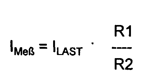
- the current flowing through the resistor R1 corresponding to the load current I R1 Storm I LOAD in the order of 0 - 1A.
- the current flowing through the resistor R2 current I R2 is the measured current which is I measurement in the mA range.
- the voltage drop across the resistor R1 corresponds to the current I LAST flowing through the load and the voltage drop across the resistor R2 represents a comparison potential.
- the two measured voltage potentials are compared with one another by the operational amplifier V.
- the operational amplifier V controls the transistor T1 until the voltage drop U R2 across the resistor R2 is equal to the voltage drop U R1 across the resistor R1.
- R1 / R2 is therefore the factor for converting the currents.
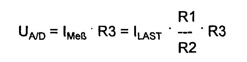
- An evaluable current measurement signal I Meß is obtained by current damping.
- this measuring current I meas must be adapted to the input voltage range of the A / D converter A / D. This is done through resistor R3. The following voltage is therefore present at the A / D converter of the control unit
- the control unit S compares the current I LAST measured in this way as the actual value with a setpoint I TARGET stored in it. Depending on this comparison, the pulse width ratio of the control signal is changed.
- I LAST > I TARGET the PWM signal from control unit S is reduced. If I LAST ⁇ I TARGET , the PWM signal is increased. If there is a match, the PWM signal is retained.
- the circuit arrangement according to the invention advantageously has a Voltage doubling device for the operational amplifier V.
- the transistor T2 is constant with controlled by a PWM signal of 50%.
- the resistor R5 is permanently connected to ground. Is the operating voltage U B z. B. 12 V, the capacitor C3 connected to 0 V charges to 12 V. 12 V is also set at the capacitor C4 and is therefore also present at the operational amplifier V.
- the transistor T2 is blocked (low signal), the capacitor is connected C3 basically to 12 V.
- the diode D2 blocks because of the connection point the diode D2 is present with the capacitor C3 24 V. This 24 V are also on capacitor C4. Thus, V are at the opration amplifier 24 V operating voltage.
Abstract
Description
Claims (9)
- Schaltungsanordnung zur Überwachung von durch Lasten fließenden Strömen, insbesondere für Kraftfahrzeuge, mit einer in Reihe zur Last geschalteten Strommeßeinrichtung, welche mit einer Vergleichseinrichtung verbunden ist, dadurch gekennzeichnet, daß eine Stromumsetzungseinrichtung (R2) mit einer Auswerteeinheit (S) verbunden ist, wobei in Abhängigkeit eines von der Stromumsetzungseinrichtung (R2) bereitgestellten Referenzwertes die Vergleichseinrichtung (V) den an der Auswerteeinheit (S) anliegenden Strom steuert.
- Schaltungsanordnung nach Anspruch 1, dadurch gekennzeichnet, daß zwischen der Stromumsetzungsseinrichtung (R2) und der Auswerteeinheit (S) ein Stromspiegel (T1, R3) geschaltet ist, welcher vom Ausgang der Vergleichseinrichtung (V) derart gesteuert wird, daß der Spannungsabfall an der Strommeßeinrichtung (R1) annähernd gleich dem Spannungsabfall an der Stromumsetzungseinrichtung (R2) ist.
- Schaltungsanordnung nach Anspruch 1 oder 2, dadurch gekennzeichnet, daß die Stromumsetzungseinrichtung (R2) einen inneren Widerstand aufweist, welcher größer ist als der innere Widerstand der Strommeßeinrichtung (R1).
- Schaltungsanordnung nach einem der vorhergehenden Ansprüche, dadurch gekennzeichnet, daß die Vergleichseinrichtung (V) ein Differenzverstärker ist.
- Schaltungsanordnung nach Anspruch 1 oder 2, dadurch gekennzeichnet, daß das Signal über eine Glättungseinrichtung (R4, C2), an die Auswerteeinheit (S) geführt ist.
- Schaltungsanordnung nach Anspruch 1 oder 4, dadurch gekennzeichnet, daß an die Vergleichseinrichtung (V) eine Betriebsspannungserhöhungsschaltung (E) geführt ist
- Schaltungsanordnung nach Anspruch 1, dadurch gekennzeichnet, daß die Last eine induktive Last ist.
- Schaltungsanordnung nach Anspruch 7, dadurch gekennzeichnet, daß die induktive Last ein Ventil zum Steuern eines Kompressors einer Klimaanlage ist.
- Schaltungsanordnung nach Anspruch 1, 7 oder 8, dadurch gekennzeichnet, daß die Ansteuerung der Last (L) mit Hilfe eines pulsweitenmodulierten Signals erfolgt.
Applications Claiming Priority (2)
| Application Number | Priority Date | Filing Date | Title |
|---|---|---|---|
| DE1997129904 DE19729904A1 (de) | 1997-07-12 | 1997-07-12 | Schaltungsanordnung zur Überwachung von durch eine Last fließenden Strömen |
| DE19729904 | 1997-07-12 |
Publications (2)
| Publication Number | Publication Date |
|---|---|
| EP0890844A2 true EP0890844A2 (de) | 1999-01-13 |
| EP0890844A3 EP0890844A3 (de) | 2000-07-19 |
Family
ID=7835499
Family Applications (1)
| Application Number | Title | Priority Date | Filing Date |
|---|---|---|---|
| EP98111393A Withdrawn EP0890844A3 (de) | 1997-07-12 | 1998-06-20 | Schaltungsanordnung zur Überwachung von durch eine Last fliessenden Strömen |
Country Status (2)
| Country | Link |
|---|---|
| EP (1) | EP0890844A3 (de) |
| DE (1) | DE19729904A1 (de) |
Cited By (2)
| Publication number | Priority date | Publication date | Assignee | Title |
|---|---|---|---|---|
| US7221208B2 (en) | 2003-01-16 | 2007-05-22 | Shindengen Electric Manufacturing Co., Ltd. | Switching circuit |
| US7248452B2 (en) | 2002-07-12 | 2007-07-24 | Yazaki Corporation | Method of protecting semiconductor device and protection apparatus for semiconductor device using the same |
Families Citing this family (2)
| Publication number | Priority date | Publication date | Assignee | Title |
|---|---|---|---|---|
| DE10202289A1 (de) * | 2002-01-22 | 2003-07-31 | Siemens Ag | Treiberschaltung |
| DE10202769B4 (de) | 2002-01-25 | 2019-02-14 | Phoenix Contact Gmbh & Co. Kg | Schaltungsanordnung für Stromquelle mit Unterbrechungserkennung |
Citations (6)
| Publication number | Priority date | Publication date | Assignee | Title |
|---|---|---|---|---|
| JPS5995706A (ja) * | 1982-11-24 | 1984-06-01 | Nippon Gakki Seizo Kk | 増幅器 |
| EP0294880A2 (de) * | 1987-06-08 | 1988-12-14 | Philips Electronics Uk Limited | Differenzverstärker und Strommessschaltung mit einem solchen Verstärker |
| US5081379A (en) * | 1985-12-10 | 1992-01-14 | U.S. Philips Corporation | Current-sensing circuit for an ic power semiconductor device |
| EP0572162A2 (de) * | 1992-05-29 | 1993-12-01 | STMicroelectronics, Inc. | Sense FET und schneller Verstärker |
| US5287055A (en) * | 1990-01-09 | 1994-02-15 | Siemens Automotive S.A. | Circuit for measuring current in a power MOS transistor |
| EP0697569A1 (de) * | 1994-07-26 | 1996-02-21 | Fujitsu General Limited | Vorrichtung zum Regeln der Motoren einer Klimaanlage |
Family Cites Families (4)
| Publication number | Priority date | Publication date | Assignee | Title |
|---|---|---|---|---|
| US4453194A (en) * | 1982-03-01 | 1984-06-05 | International Business Machines Corporation | Integrated power circuit with current sensing means |
| DE3441015A1 (de) * | 1984-11-09 | 1986-05-15 | Siemens AG, 1000 Berlin und 8000 München | Schaltung zur ueberwachung des stromflusses durch n verbraucher |
| FR2628217B1 (fr) * | 1988-03-07 | 1990-07-27 | Sgs Thomson Microelectronics | Circuit de mesure d'un courant |
| JP3080823B2 (ja) * | 1993-10-15 | 2000-08-28 | モトローラ株式会社 | 半導体集積回路装置 |
-
1997
- 1997-07-12 DE DE1997129904 patent/DE19729904A1/de not_active Ceased
-
1998
- 1998-06-20 EP EP98111393A patent/EP0890844A3/de not_active Withdrawn
Patent Citations (6)
| Publication number | Priority date | Publication date | Assignee | Title |
|---|---|---|---|---|
| JPS5995706A (ja) * | 1982-11-24 | 1984-06-01 | Nippon Gakki Seizo Kk | 増幅器 |
| US5081379A (en) * | 1985-12-10 | 1992-01-14 | U.S. Philips Corporation | Current-sensing circuit for an ic power semiconductor device |
| EP0294880A2 (de) * | 1987-06-08 | 1988-12-14 | Philips Electronics Uk Limited | Differenzverstärker und Strommessschaltung mit einem solchen Verstärker |
| US5287055A (en) * | 1990-01-09 | 1994-02-15 | Siemens Automotive S.A. | Circuit for measuring current in a power MOS transistor |
| EP0572162A2 (de) * | 1992-05-29 | 1993-12-01 | STMicroelectronics, Inc. | Sense FET und schneller Verstärker |
| EP0697569A1 (de) * | 1994-07-26 | 1996-02-21 | Fujitsu General Limited | Vorrichtung zum Regeln der Motoren einer Klimaanlage |
Non-Patent Citations (1)
| Title |
|---|
| PATENT ABSTRACTS OF JAPAN vol. 008, no. 209 (E-268), 22. September 1984 (1984-09-22) & JP 59 095706 A (NIPPON GAKKI SEIZO KK), 1. Juni 1984 (1984-06-01) * |
Cited By (2)
| Publication number | Priority date | Publication date | Assignee | Title |
|---|---|---|---|---|
| US7248452B2 (en) | 2002-07-12 | 2007-07-24 | Yazaki Corporation | Method of protecting semiconductor device and protection apparatus for semiconductor device using the same |
| US7221208B2 (en) | 2003-01-16 | 2007-05-22 | Shindengen Electric Manufacturing Co., Ltd. | Switching circuit |
Also Published As
| Publication number | Publication date |
|---|---|
| DE19729904A1 (de) | 1999-02-11 |
| EP0890844A3 (de) | 2000-07-19 |
Similar Documents
| Publication | Publication Date | Title |
|---|---|---|
| DE69736260T2 (de) | Leistungsfaktorkorrekturschaltung | |
| DE19814681B4 (de) | Current-Mode-Schaltregler | |
| DE19920306B4 (de) | Schaltungsvorrichtung zum Regeln des Stroms durch eine induktive Last | |
| EP0483891B1 (de) | Auswerteschaltung für einen magnetoresistiven Drehzahlsensor o.dgl. | |
| DE19526435B4 (de) | Schaltungsanordnung zur Fehlerstromerkennung | |
| DE19749392B4 (de) | Strommeßschaltung | |
| DE102004010707A1 (de) | Energiezähleranordnung und Verfahren zum Kalibrieren | |
| DE19920307A1 (de) | Elektrische Schaltung zum Steuern einer Last | |
| EP1669765A1 (de) | Schaltungsanordnung zur Messung eines elektrischen Stromes | |
| DE102007046560A1 (de) | Feldgerät mit einem Analogausgang | |
| DE19642472A1 (de) | Flußkompensierter Stromsensor | |
| EP1703629B1 (de) | Verfahren zur digitalen Stromregelung | |
| DE19963384C2 (de) | Schaltungsanordnung zur Überwachung eines zum Steuern einer Last vorgesehenen elektronischen Schalters | |
| EP0358122B1 (de) | Temperatursensor | |
| EP0890844A2 (de) | Schaltungsanordnung zur Überwachung von durch eine Last fliessenden Strömen | |
| DE3803611A1 (de) | Schaltgeregelte stroemungssonde | |
| WO1997027487A1 (de) | Schaltungsanordnung zur anpassung eines aktiven sensors an eine auswerteschaltung | |
| DE102019210566A1 (de) | Vorrichtung und Verfahren zum Messen eines durch eine PWM-angesteuerte induktive Last fließenden Stromes | |
| DE10062190C1 (de) | Verfahren und Vorrichtung zur Funktionsüberwachung einer Endstufe mit Pulsweitenmodulation | |
| DE102009022135A1 (de) | Schaltungsanordnung zur Messung von elektrischem Strom | |
| EP1644208A1 (de) | Verfahren zur messung eines drucks | |
| DE19844726A1 (de) | Stromsensor nach dem Kompensationsprinzip | |
| DE102019219759B4 (de) | Schaltungsanordnung zum Erfassen eines durch eine bipolare Last fließenden Stroms | |
| DE102008031906B4 (de) | Steuergerät und Verfahren zum Betreiben eines Steuergeräts | |
| DE10057375C1 (de) | Temperaturüberwachungsschaltung für pulsweitenmoduliert betriebene, geregelte induktive Verbraucher |
Legal Events
| Date | Code | Title | Description |
|---|---|---|---|
| PUAI | Public reference made under article 153(3) epc to a published international application that has entered the european phase |
Free format text: ORIGINAL CODE: 0009012 |
|
| AK | Designated contracting states |
Kind code of ref document: A2 Designated state(s): DE ES FR GB SE |
|
| AX | Request for extension of the european patent |
Free format text: AL;LT;LV;MK;RO;SI |
|
| PUAL | Search report despatched |
Free format text: ORIGINAL CODE: 0009013 |
|
| AK | Designated contracting states |
Kind code of ref document: A3 Designated state(s): AT BE CH CY DE DK ES FI FR GB GR IE IT LI LU MC NL PT SE |
|
| AX | Request for extension of the european patent |
Free format text: AL;LT;LV;MK;RO;SI |
|
| 17P | Request for examination filed |
Effective date: 20001215 |
|
| AKX | Designation fees paid |
Free format text: DE ES FR GB SE |
|
| RAP1 | Party data changed (applicant data changed or rights of an application transferred) |
Owner name: SIEMENS AKTIENGESELLSCHAFT |
|
| 17Q | First examination report despatched |
Effective date: 20050907 |
|
| RAP1 | Party data changed (applicant data changed or rights of an application transferred) |
Owner name: CONTINENTAL AUTOMOTIVE GMBH |
|
| STAA | Information on the status of an ep patent application or granted ep patent |
Free format text: STATUS: THE APPLICATION IS DEEMED TO BE WITHDRAWN |
|
| 18D | Application deemed to be withdrawn |
Effective date: 20080716 |