EP0890323A2 - Schnürhaken - Google Patents
Schnürhaken Download PDFInfo
- Publication number
- EP0890323A2 EP0890323A2 EP98201231A EP98201231A EP0890323A2 EP 0890323 A2 EP0890323 A2 EP 0890323A2 EP 98201231 A EP98201231 A EP 98201231A EP 98201231 A EP98201231 A EP 98201231A EP 0890323 A2 EP0890323 A2 EP 0890323A2
- Authority
- EP
- European Patent Office
- Prior art keywords
- lacing
- cleat
- cheek
- cleat according
- channel
- Prior art date
- Legal status (The legal status is an assumption and is not a legal conclusion. Google has not performed a legal analysis and makes no representation as to the accuracy of the status listed.)
- Withdrawn
Links
- 230000000452 restraining effect Effects 0.000 claims description 3
- 230000003014 reinforcing effect Effects 0.000 claims description 2
- 230000000694 effects Effects 0.000 description 1
- 238000005096 rolling process Methods 0.000 description 1
Images
Classifications
-
- A—HUMAN NECESSITIES
- A43—FOOTWEAR
- A43C—FASTENINGS OR ATTACHMENTS OF FOOTWEAR; LACES IN GENERAL
- A43C3/00—Hooks for laces; Guards for hooks
- A43C3/02—Lacing-hooks with guide rollers
Definitions
- the present invention relates to a lacing cleat for a laced fastening comprising a first and a second cheek which are disposed side by side and between which a channel is defined. It is known to make footwear with a laced fastening in which the lace is guided through suitable cleats. The surfaces of known cleats offer a certain friction to the sliding of the lace, making it very difficult to fasten the lace of the fastening with the desired force.
- a primary object of the present invention is to provide lacing cleats which are designed structurally and functionally to offer less friction to the sliding of the lace.
- Another object of the invention is to provide a cleat which can restrain the lace once it is engaged in the channel.
- a further object is to provide a cleat which, whilst achieving the advantages set out above, can be produced at low cost.
- One of the chief objects of the invention is to provide a cleat which is particularly strong and permits both conventional lacing and lacing with a purchase effect, and which is suitable for clamping the lace.
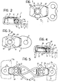
- a first embodiment of a lacing cleat formed in accordance with the present invention is generally indicated 1.
- the cleat 1 comprises an attachment plate 2 through which one or more holes 3 extend and by which the cleat is attached to a respective flap 3a, 3b of a footwear upper ( Figure 5) by means of rivets 3c or the like.
- the plate 2 is extended to form a first and a second cheek 4, 5 which jointly define a channel 6 closed by an end portion 7 and open at the opposite end, that is, at an opening 9.
- a cylindrical, pin-like appendage 10 extends between the cheeks 4, 5 and is preferably formed by drawing of the central region of the first cheek 4 towards the second cheek 5.
- the appendage 10 has a tubular shape, open at both axial ends, and preferably opens beyond the second cheek 5 in the region of a hole 10a thereof, without, however, any mechanical connection between the end of the appendage 10 and the second cheek.
- the surface of the end 7 of the channel 6 and the opposite surface of the appendage 10 define, respectively, a second and a first lacing surface on which a lace 11 can be guided for sliding as described further below.
- a narrow section is formed at the opening 9 of the channel 6 and is defined by the two cheeks 4, 5 which have, respectively, a projection 13 and a lip 14 facing one another and projecting towards the interior of the channel 6 in order to restrict its opening.
- This narrow section constitutes a restraining means for holding the lace 11 against the first lacing surface of the appendage 10 once it is engaged in the cleat 1.
- cheeks 4, 5 are connected to one another solely at the end 7 of the channel 6, they have a limited ability to move apart resiliently which, together with the resilient deformability of the lace, allows the latter to pass through the opening 9 of the channel 6 in order to be engaged in the cleat 1 where it remains held until it is forced out of the channel.
- the lace is arranged for lacing, it therefore remains in its position of engagement in the cleats until it is deliberately removed.
- the second cheek 5 has a plurality of reinforcing ribs 15 projecting in relief towards the inside of the channel 6, towards the other cheek 4.
- the ribs 15 extend approximately radially relative to the axis of the appendage 10.
- the cleat 20 has a pulley 21 mounted idly on the appendage 10 which, in this embodiment, constitutes the pin of the pulley.
- the first lacing surface is therefore defined on the race 22 of the pulley 21. The sliding friction between the lace and the cleat is thus transformed into rolling friction, further improving the ability of the lace to slide.
- a lace 11 is engaged in the cleat 1 or 20 through the opening 9 so as to bear in sliding contact on the first lacing surface defined on the appendage 10 or on the race of the pulley 21, respectively. If it is desired to achieve a greater tightening load for a given tension applied to the ends of the lace and, at the same time, a clamping of the lace, in terms of greater resistance offered to the release of the lacing, the lace 11 can be passed through the lacing cleats in the manner shown in Figure 5. Typically, this solution is implemented in the pairs of cleats which enclose the instep of the foot.
- the lace coming from the lower portion or toe of the footwear is first inserted against the end surface 7 of the channel 6 of one of the cleats 20 and is then passed over the appendage 10 or pulley 21 of the opposite cleat 20.
- a connection with purchase is thus achieved between the cleats and amplifies the tightening and clamping force, or opposes the release of the lace under load.
- the invention thus achieves the purposes and advantages indicated.
Landscapes
- Footwear And Its Accessory, Manufacturing Method And Apparatuses (AREA)
- Decoration Of Textiles (AREA)
- Knitting Of Fabric (AREA)
- Braiding, Manufacturing Of Bobbin-Net Or Lace, And Manufacturing Of Nets By Knotting (AREA)
Applications Claiming Priority (2)
| Application Number | Priority Date | Filing Date | Title |
|---|---|---|---|
| ITPD970155 | 1997-07-11 | ||
| IT97PD000155 IT1294786B1 (it) | 1997-07-11 | 1997-07-11 | Gancio passa-lacci per allacciature a stringa |
Publications (2)
| Publication Number | Publication Date |
|---|---|
| EP0890323A2 true EP0890323A2 (de) | 1999-01-13 |
| EP0890323A3 EP0890323A3 (de) | 1999-06-09 |
Family
ID=11391862
Family Applications (1)
| Application Number | Title | Priority Date | Filing Date |
|---|---|---|---|
| EP98201231A Withdrawn EP0890323A3 (de) | 1997-07-11 | 1998-04-17 | Schnürhaken |
Country Status (2)
| Country | Link |
|---|---|
| EP (1) | EP0890323A3 (de) |
| IT (1) | IT1294786B1 (de) |
Cited By (3)
| Publication number | Priority date | Publication date | Assignee | Title |
|---|---|---|---|---|
| GB2369986A (en) * | 2000-12-01 | 2002-06-19 | Gary James Aronsson | Hook for laces |
| EP1588640A1 (de) * | 2004-04-23 | 2005-10-26 | The Swatch Group Management Services AG | Längeneinstellungsvorrichtung eines Bandes, insbesondere für ein Uhrarmband |
| KR101663043B1 (ko) * | 2015-10-06 | 2016-10-11 | 김성태 | 신발끈용 후크, 이를 포함하는 신발 및 신발끈 결속방법 |
Family Cites Families (2)
| Publication number | Priority date | Publication date | Assignee | Title |
|---|---|---|---|---|
| AT242560B (de) * | 1963-07-18 | 1965-09-27 | Karl Piberhofer | Schnürhaken |
| DE1883745U (de) * | 1963-07-27 | 1963-11-28 | Stocko Metallwarenfabriken Hug | Rollenhaken, insbesondere fuer skischuhe. |
-
1997
- 1997-07-11 IT IT97PD000155 patent/IT1294786B1/it active IP Right Grant
-
1998
- 1998-04-17 EP EP98201231A patent/EP0890323A3/de not_active Withdrawn
Non-Patent Citations (1)
| Title |
|---|
| None |
Cited By (3)
| Publication number | Priority date | Publication date | Assignee | Title |
|---|---|---|---|---|
| GB2369986A (en) * | 2000-12-01 | 2002-06-19 | Gary James Aronsson | Hook for laces |
| EP1588640A1 (de) * | 2004-04-23 | 2005-10-26 | The Swatch Group Management Services AG | Längeneinstellungsvorrichtung eines Bandes, insbesondere für ein Uhrarmband |
| KR101663043B1 (ko) * | 2015-10-06 | 2016-10-11 | 김성태 | 신발끈용 후크, 이를 포함하는 신발 및 신발끈 결속방법 |
Also Published As
| Publication number | Publication date |
|---|---|
| ITPD970155A1 (it) | 1999-01-11 |
| EP0890323A3 (de) | 1999-06-09 |
| IT1294786B1 (it) | 1999-04-15 |
Similar Documents
| Publication | Publication Date | Title |
|---|---|---|
| EP1014822B1 (de) | Schnürhaken für schnürverschlüsse | |
| US7287304B2 (en) | Cam cleat construction | |
| US6119372A (en) | Snowboard boot power lacing configuration | |
| GB2284340A (en) | Shoelace fastening device | |
| US5906057A (en) | Sports boot including flexible and traction resistant return elements | |
| US6554297B2 (en) | Dive resistant buckle | |
| US5687460A (en) | Fastening device particularly for sports shoes | |
| US6701590B2 (en) | Unique systems and methods for locking footwear | |
| US5335400A (en) | Drawstring puller and fastener for shoelaces | |
| US20020083621A1 (en) | Lacing device | |
| DE69903840T2 (de) | Schnürvorrichtung für schuhsenkel | |
| US5873183A (en) | Shoe securement apparatus with lace and groove fasteners | |
| JP2001518331A (ja) | スノーボード安全解除締め具 | |
| EP1064863A1 (de) | System zum Spannen von Schnürsenkeln, insbesondere für Sportschuhe | |
| JPH1080305A (ja) | スポーツ靴用の可変断面を有する紐およびこの種の紐を備えたスポーツ靴 | |
| EP0890323A2 (de) | Schnürhaken | |
| US5592722A (en) | Closure device, particularly for sports shoes | |
| CA2116051A1 (en) | Engagement device particularly for toothed bands for sports shoes | |
| US20240225199A1 (en) | Locking Boot Fastening Device and Method | |
| CN109068801B (zh) | 用于紧固内鞋的鞋带 | |
| US3537151A (en) | Shoelace clasp | |
| US6016590A (en) | Lace wraps | |
| US20040226189A1 (en) | Mountable securing mechanism for lace type footgear and method of using thereof | |
| US11980252B2 (en) | Dynamic lacing system | |
| US3239903A (en) | Tension element |
Legal Events
| Date | Code | Title | Description |
|---|---|---|---|
| PUAI | Public reference made under article 153(3) epc to a published international application that has entered the european phase |
Free format text: ORIGINAL CODE: 0009012 |
|
| AK | Designated contracting states |
Kind code of ref document: A2 Designated state(s): AT BE CH CY DE DK ES FI FR GB GR IE IT LI LU MC NL PT SE |
|
| AX | Request for extension of the european patent |
Free format text: AL;LT;LV;MK;RO;SI |
|
| PUAL | Search report despatched |
Free format text: ORIGINAL CODE: 0009013 |
|
| AK | Designated contracting states |
Kind code of ref document: A3 Designated state(s): AT BE CH CY DE DK ES FI FR GB GR IE IT LI LU MC NL PT SE |
|
| AX | Request for extension of the european patent |
Free format text: AL;LT;LV;MK;RO;SI |
|
| RIC1 | Information provided on ipc code assigned before grant |
Free format text: 6A 43C 3/02 A, 6A 43C 3/00 B |
|
| AKX | Designation fees paid | ||
| REG | Reference to a national code |
Ref country code: DE Ref legal event code: 8566 |
|
| STAA | Information on the status of an ep patent application or granted ep patent |
Free format text: STATUS: THE APPLICATION IS DEEMED TO BE WITHDRAWN |
|
| 18D | Application deemed to be withdrawn |
Effective date: 19991210 |