EP0890145B1 - Devices for metering fluids in response to level changes - Google Patents
Devices for metering fluids in response to level changes Download PDFInfo
- Publication number
- EP0890145B1 EP0890145B1 EP97915526A EP97915526A EP0890145B1 EP 0890145 B1 EP0890145 B1 EP 0890145B1 EP 97915526 A EP97915526 A EP 97915526A EP 97915526 A EP97915526 A EP 97915526A EP 0890145 B1 EP0890145 B1 EP 0890145B1
- Authority
- EP
- European Patent Office
- Prior art keywords
- liquid
- container
- auxiliary container
- main container
- calibration member
- Prior art date
- Legal status (The legal status is an assumption and is not a legal conclusion. Google has not performed a legal analysis and makes no representation as to the accuracy of the status listed.)
- Expired - Lifetime
Links
Images

Classifications
-
- E—FIXED CONSTRUCTIONS
- E03—WATER SUPPLY; SEWERAGE
- E03D—WATER-CLOSETS OR URINALS WITH FLUSHING DEVICES; FLUSHING VALVES THEREFOR
- E03D9/00—Sanitary or other accessories for lavatories ; Devices for cleaning or disinfecting the toilet room or the toilet bowl; Devices for eliminating smells
- E03D9/02—Devices adding a disinfecting, deodorising, or cleaning agent to the water while flushing
- E03D9/03—Devices adding a disinfecting, deodorising, or cleaning agent to the water while flushing consisting of a separate container with an outlet through which the agent is introduced into the flushing water, e.g. by suction ; Devices for agents in direct contact with flushing water
- E03D9/033—Devices placed inside or dispensing into the cistern
- E03D9/038—Passive dispensers, i.e. without moving parts
-
- G—PHYSICS
- G05—CONTROLLING; REGULATING
- G05D—SYSTEMS FOR CONTROLLING OR REGULATING NON-ELECTRIC VARIABLES
- G05D11/00—Control of flow ratio
- G05D11/001—Control of flow ratio with discontinuous action
-
- G—PHYSICS
- G05—CONTROLLING; REGULATING
- G05D—SYSTEMS FOR CONTROLLING OR REGULATING NON-ELECTRIC VARIABLES
- G05D11/00—Control of flow ratio
- G05D11/006—Control of flow ratio involving a first fluid acting on the feeding of a second fluid
-
- Y—GENERAL TAGGING OF NEW TECHNOLOGICAL DEVELOPMENTS; GENERAL TAGGING OF CROSS-SECTIONAL TECHNOLOGIES SPANNING OVER SEVERAL SECTIONS OF THE IPC; TECHNICAL SUBJECTS COVERED BY FORMER USPC CROSS-REFERENCE ART COLLECTIONS [XRACs] AND DIGESTS
- Y10—TECHNICAL SUBJECTS COVERED BY FORMER USPC
- Y10T—TECHNICAL SUBJECTS COVERED BY FORMER US CLASSIFICATION
- Y10T137/00—Fluid handling
- Y10T137/4891—With holder for solid, flaky or pulverized material to be dissolved or entrained
Definitions
- the present invention relates to a method for dosing a fluid initially contained in a reservoir R1, said dosing being ensured by the use of variations in the level of a liquid contained in a tank R32, this so-called level variation allowing the transfer of quantities of fluids controlled from one tank to another and in the pipes linking these two reservoirs.
- the purpose of the device according to the invention is to deliver from a auxiliary container a calibrated volume of a first liquid in a container main containing a second liquid provided with means for controlling filling and emptying cycles of said second liquid.
- the main container and the auxiliary container present a communication orifice between them.
- the auxiliary container comprises a calibration element having a general vertical direction and having a lower end and an upper end, said lower end of the calibration element being connected to said container main to allow said first or second liquid to enter said element for calibrating a height in relation to the height of the second liquid in said main container when filling said main container, by flow of the first liquid to the container auxiliary through said communication orifice.
- Means are in further provided for controlling the output of a volume of said first liquid outside said auxiliary container substantially equal to the volume of the first or second liquid having entered said calibration element during a emptying phase of said main container, by draining the second liquid to the main container through said communication port.
- this system makes it possible to dose the air escaping from piping 205 in proportion to the variation in level 213 and to section s.
- Figure 2 gives a variant of the previous system characterized in that the drops 220 from piping 209 fall into a receiving cone 221, then into piping 222 of smaller diameter than piping 207. This makes it possible to prevent the fluid coming from R1 does not stagnate above the fluid sucked in 207 during the R2 filling phase. Its arrival in the R2 tank would then be postponed during emptying. On the contrary, using this tube 222, the levels 212 and 223 in the tubes 207 and 222 being almost identical when the densities of the fluids 203 and 204 are close, the transit time of the fluid 203 towards the end 224 of the tube 222 will be much faster than in the previous case.
- the gear ratio of descent between the present case and the case of Figure 2 is equal to s / s ', s and s' being respectively the ratios of the sections of the useful part of the piping 207 to that of the piping 222.
- the fluid to be metered can therefore arrive very quickly in R2.
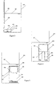
- FIG. 3 represents a dispenser intended for injecting a dose of a liquid saturated in a product dissolved from a solid matter each time an R2 tank (402) is drained.
- the liquid saturated with dissolved product 404 is contained in a tank R1 (401) provided a small orifice 403 at its upper part.
- R1 contains SS 405 which keep the liquid 404 in saturated state whatever the variations of temperature.
- This small tank R1 is also provided with a large piping length 406, the open top of which is located above the top level of the tank.
- the section of this piping 406 is denoted s.
- R1 Before filling R2, it is assumed that R1 is filled with a saturated liquid whose high level is that of port 403.
- level 407 in R2 goes up as well as level 408 in tube 406. These levels are equal if we neglect the effects of surface tension and close to each other otherwise.
- liquid from R2 enters R1. This liquid mixes with the liquid already present in R1 and becomes saturated in the material dissolved.
- R2 emptying occurs, the level drops in R2 and in the tube 406. Liquid is therefore ejected from R1 and mixes with the liquid contained in R2.
- FIG. 4 represents a dispenser intended for injecting a dose of a liquid saturated in a product dissolved from a solid matter each time an R2 tank (502) is drained.
- the liquid saturated with product below 504 is contained in a tank R1 (501) provided a small opening 503 at its upper part.
- R1 contains soluble materials 505 which allow to keep the liquid 504 in saturated state whatever the variations of temperature.
- This small tank R1 is also provided with a tank 506, the summit is closed.
- This tank 506 contains air provided that the orifice 503 is disposed at the base of said tank 506.
- R1 is filled with a saturated liquid whose high level is that of port 503.
- level 507 in R2 rises as well as the level and pressure in the tank 506 due to the compressibility of gases.
- liquid from R2 enters R1. This liquid mixes with the liquid already present in R1 and saturates in the dissolved matter.
- R2 emptying occurs, the level drops in R2 and in tank 506. Saturated liquid is therefore ejected from R1 and mixes with the liquid contained in R2.
- This system is therefore also a particularly simple way to introduce a flow of a liquid saturated with material dissolved proportional to a main flow. Accuracy of the volume ratio transferred during a drain can be quite excellent.
- This system constitutes therefore, like the system described in FIG. 4, an inexpensive dosing device, precise and particularly reliable.
- FIG. 5 represents a variant of the solution represented in FIG. 4 in which the air contained in R2 is placed in a flexible envelope 510, which allows to prevent it from dissolving in the liquid contained in said reservoir.
- the orifice 503 of communication of R2 with the fluid contained in the tank R1 502 is placed indifferently in the upper, lower or lateral part of the tank as it is the case on figure 6. This tank can possibly undergo azimuthal position changes without losing its effectiveness.
Landscapes
- Engineering & Computer Science (AREA)
- Physics & Mathematics (AREA)
- Automation & Control Theory (AREA)
- Public Health (AREA)
- Health & Medical Sciences (AREA)
- General Physics & Mathematics (AREA)
- Life Sciences & Earth Sciences (AREA)
- Water Supply & Treatment (AREA)
- Hydrology & Water Resources (AREA)
- Epidemiology (AREA)
- Feeding, Discharge, Calcimining, Fusing, And Gas-Generation Devices (AREA)
- Loading And Unloading Of Fuel Tanks Or Ships (AREA)
- Devices For Dispensing Beverages (AREA)
Description
Dans les nombreuses applications mettant en jeu des opérations de dosage, il est très fréquent que l'on doive injecter des quantités de fluides selon une fonction prédéfinie de la variation de niveau du liquide contenu dans un réservoir. Très souvent, les quantités injectées doivent être proportionnelles à la variation du niveau ou du volume de liquide dans le réservoir, ladite fonction étant alors linéaire relativement au volume ou au débit.In the numerous applications involving operations of dosage, it is very common to have to inject quantities of fluids according to a predefined function of the level variation of the liquid contained in a tank. Very often the quantities injected must be proportional to the variation in the level or volume of liquid in the reservoir, said function then being linear relative to the volume or to the debit.
Ces opérations nécessitent en général la mise en oeuvre de matériels complexes, par exemple un ensemble formé d'un détecteur de niveau, d'une pompe doseuse et d'un régulateur. Ce type de matériel est souvent cher, comporte des pièces mécaniques et des pièces d'étanchéité susceptibles de se déteriorer dans le temps et peut poser des problèmes d'utilisation dans des ambiances agressives, explosives ou d'accès règlementé.These operations generally require the implementation of complex materials, for example an assembly formed by a level, a metering pump and a regulator. This type of material is often expensive, has mechanical parts and sealing parts likely to deteriorate over time and may cause problems for use in aggressive, explosive or access environments regulated.
On connait par ailleurs des dispositifs qui, sous l'effet de la pression engendrée par la montée d'un premier fluide permettent simultanément à cette montée de délivrer un second fluide. De tels dispositifs sont décrits dans les documents de brevet US-A-1 728 737, US-A-1 623 132 et EP-A-0 570 326.There are also known devices which, under the effect of the pressure generated by the rise of a first fluid allow simultaneously with this rise to deliver a second fluid. Such devices are described in patent documents US-A-1,728,737, US-A-1,623,132 and EP-A-0 570 326.
La présente invention est relative à un procédé de dosage d'un fluide initialement contenu dans un réservoir R1, ledit dosage étant assuré par l'utilisation des variations de niveau d'un liquide contenu dans un réservoir R32, cette dite variation de niveau permettant le transfert de quantités de fluides maitrisées d'un réservoir à l'autre et dans les tuyauteries liant ces deux réservoirs.The present invention relates to a method for dosing a fluid initially contained in a reservoir R1, said dosing being ensured by the use of variations in the level of a liquid contained in a tank R32, this so-called level variation allowing the transfer of quantities of fluids controlled from one tank to another and in the pipes linking these two reservoirs.
Le dispositif selon l'invention a pour but de délivrer depuis un récipient auxiliaire un volume calibré d'un premier liquide dans un récipient principal contenant un deuxième liquide muni de moyens pour commander des cycles de remplissage et de vidange dudit deuxième liquide.The purpose of the device according to the invention is to deliver from a auxiliary container a calibrated volume of a first liquid in a container main containing a second liquid provided with means for controlling filling and emptying cycles of said second liquid.
Selon l'invention, le récipient principal et le récipient auxiliaire présentent entre eux un orifice de communication.According to the invention, the main container and the auxiliary container present a communication orifice between them.
Selon l'invention également, le récipient auxiliaire comprend un élément de calibrage présentant une direction générale verticale et comportant une extrémité inférieure et une extrémité supérieure, ladite extrémité inférieure de l'élément de calibrage étant reliée audit récipient principal pour permettre audit premier ou deuxième liquide de pénétrer dans ledit élément de calibrage d'une hauteur en relation avec la hauteur du deuxième liquide dans ledit récipient principal lors du remplissage dudit récipient principal, par écoulement du premier liquide vers le récipient auxiliaire au travers dudit orifice de communication. Des moyens sont en outre prévus pour commander la sortie d'un volume dudit premier liquide hors dudit récipient auxiliaire sensiblement égal au volume du premier ou du deuxième liquide ayant pénétré dans ledit élément de calibrage lors d'une phase de vidange dudit récipient principal, par écoulement du second liquide vers le récipient principal au travers dudit orifice de communication.According to the invention also, the auxiliary container comprises a calibration element having a general vertical direction and having a lower end and an upper end, said lower end of the calibration element being connected to said container main to allow said first or second liquid to enter said element for calibrating a height in relation to the height of the second liquid in said main container when filling said main container, by flow of the first liquid to the container auxiliary through said communication orifice. Means are in further provided for controlling the output of a volume of said first liquid outside said auxiliary container substantially equal to the volume of the first or second liquid having entered said calibration element during a emptying phase of said main container, by draining the second liquid to the main container through said communication port.
D'autres caractéristiques et avantages de la présente invention apparaítront mieux à la lecture de la description qui suit des principes et plusieurs modes de mise en oeuvre de l'invention donnés à titre d'exemples non limitatifs. La description se réfère aux figures annexées sur lesquelles :
- la figure 1 illustre un mode de réalisation de l'invention dans lequel une quantité contrôlée de liquide est extraite du réservoir RI sous l'effet de la vidange du réservoir R2.
- la figure 2 illustre un autre mode de réalisation de l'appareil dans lequel le fluide extrait du résevoir R1 est introduit pratiquement sans retard dans le réservoir R2.
- la figure 3 illustre un mode de réalisation de l'appareil dans lequel du fluide issu du réservoir R2 est introduit dans le réservoir R1 sous l'effet d'une augmentation de niveau dans le réservoir R2, se mélange au fluide initialement contenu dans R1, un débit contrôlé dudit mélange étant ensuite extrait de R1 lors de la vidange de R2 par vidange d'une tuyauterie ouverte à sa partie supérieure.
- La figure 4 illustre un autre mode de réalisation de la fonction précédente dans lequel le contrôle de débit se fait dans une tuyauterie fermée formant réservoir.
- Et la figure 5 illustre une variante de réalisation de l'appareil de la figure 4.
- FIG. 1 illustrates an embodiment of the invention in which a controlled quantity of liquid is extracted from the reservoir RI under the effect of the emptying of the reservoir R2.
- FIG. 2 illustrates another embodiment of the apparatus in which the fluid extracted from the reservoir R1 is introduced practically without delay into the reservoir R2.
- FIG. 3 illustrates an embodiment of the apparatus in which fluid from the reservoir R2 is introduced into the reservoir R1 under the effect of an increase in level in the reservoir R2, mixes with the fluid initially contained in R1, a controlled flow of said mixture then being extracted from R1 during the emptying of R2 by emptying a pipe open at its upper part.
- FIG. 4 illustrates another embodiment of the previous function in which the flow control is done in a closed pipe forming a reservoir.
- And FIG. 5 illustrates an alternative embodiment of the apparatus of FIG. 4.
La figure 1 décrit un système permettant d'extraire un volume v d'un réservoir R1 lorsque le réservoir R2 est en phase de vidange. On retrouve le réservoir R1 (201) contenant le produit à diffuser 203 et le réservoir récepteur R2 (202) contenant le liquide 204 . Le réservoir R1 est muni à sa partie supérieure de deux orifices de sortie 205 et 206. L'orifice 205 est en contact avec l'atmosphère située au dessus de la surface libre 213 du réservoir R2. L'orifice 206 est, quant à lui, relié par l'intermédiaire de la tuyauterie 209 au réservoir intermédiaire 208, lui-même relié au tube plongeur 207 pénétrant dans le liquide 204 contenu dans la cuve R2. Lorsque le réservoir R2 est vide, le tube 207 est lui-même vide de liquide. Lorsqu'on verse du liquide dans le réservoir R2, le niveau 213 monte et le niveau 212 dans le tube monte également, mettant en pression l'air contenu dans la partie supérieure du tube 207. Ceci force un débit d'air à pénétrer en 210 dans le liquide contenu dans le réservoir R1 (201) Il s'échappa sous forme de bulles 215 dans le liquide 203 puis se répand dans l'atmosphère au travers du tube d'évent 205. Le niveau dans le tube 207 peut ainsi monter sans trop perturber le liquide contenu dans le réservoir R1. Lors de la vidange du réservoir R2, les niveaux 213, puis 212 baissent. Un vide relatif se crée en partie supérieure de la tuyauterie 207. Ceci force le liquide 203 contenu dans le réservoir R1 à pénétrer dans la tuyauterie 209 puis dans le réservoir 208 pour atteindre sous forme de gouttes ou de ruissellements la tuyauterie 207. L'application des lois de l'hydrostatique montre que la pression d'air dans la partie supérieure du tube 207 est pratiquement constante et égale à la pression atmosphérique si la hauteur du réservoir R1 est faible. On en déduit que le débit aspiré dans la colonne 207 est égal au produit de la vitesse de descente de la surface libre 213 par la section s de la tuyauterie 207. On retrouve donc les mêmes relations que dans le cas précédent, à savoir qu'une diminution de hauteur Δh conduit à modifier les volumes selon les lois suivantes :
- le volume de liquide pénétrant dans le réservoir R2 (202), V=S Δh
- le volume de liquide pénétrant dans le
tube 207, v=s Δh - le volume de liquide sortant du réservoir R1 (201), également égal à v=s Δh
- le rapport des volumes transférés v et V est égal au rapport des sections s et S, comme dans le cas illustré par la figure 1.
- the volume of liquid entering the reservoir R2 (202), V = S Δh
- the volume of liquid entering the
tube 207, v = s Δh - the volume of liquid leaving the reservoir R1 (201), also equal to v = s Δh
- the ratio of the transferred volumes v and V is equal to the ratio of the sections s and S, as in the case illustrated in FIG. 1.
La vidange se termine par mise à l'air libre de l'extrémité 211 de la tuyauterie 207. Le
liquide restant dans ledit tube 207 tombe alors dans le réservoir R2. le cycle peut alors
recommencer. The emptying ends by venting the
Il est possible de faire varier la position verticale du réservoir R1, avec la limitation
propre à cette application que le point- culminant de la tuyauterie 209 doit toujours
être au dessus du niveau 213.It is possible to vary the vertical position of the tank R1, with the limitation
specific to this application that the culmination of
On notera que, dans sa phase initiale de remplissage, ce système permet de doser l'air
s'échappant de la tuyauterie 205 proportionnellement à la variation du niveau 213 et à
la section s.It will be noted that, in its initial filling phase, this system makes it possible to dose the air
escaping from
La figure 2 donne une variante du système précédent caractérisé en ce que les gouttes
220 provenant de la tuyauterie 209 tombent dans un cône récepteur 221, puis dans
une tuyauterie 222 de diamètre inférieur à la tuyauterie 207. Ceci permet d'éviter que
le fluide provenant de R1 ne stagne au dessus du fluide aspiré dans 207 lors de la
phase de remplissage de R2. Son arrivée dans le réservoir R2 serait alors différée
pendant la vidange. Au contraire, en utilisant ce tube 222, les niveaux 212 et 223 dans
les tubes 207 et 222 étant quasi identiques lorsque les masses volumiques des fluides
203 et 204 sont proches, le temps de transit du fluide 203 vers l'extrémité 224 du tube
222 sera beaucoup plus rapide que dans le cas précédent. Le rapport des vitesses de
descente entre le cas présent et le cas de la figure 2 est égal à s/s', s et s' étant
respectivement les rapports des sections de la partie utile de la tuyauterie 207 à celle
de la tuyauterie 222. Le fluide à doser peut donc arriver très rapidement dans R2.Figure 2 gives a variant of the previous system characterized in that the
La figure 3 représente un doseur destiné à injecter une dose d'un liquide saturé en un
produit dissous à partir d'une matière solide à chaque vidange d'un réservoir R2 (402).
Le liquide saturé en produit dissous 404 est contenu dans un réservoir R1 (401) muni
d'un petit orifice 403 à sa partie supérieure. R1 contient des solides solubles 405 qui
permettent de garder le liquide 404 en état saturé quelles que soient les variations de
température. Ce petit réservoir R1 est muni, par ailleurs, d'une tuyauterie de grande
longueur 406 dont le sommet ouvert est situé au dessus du niveau haut du réservoir.
La section de cette tuyauterie 406 est notée s.FIG. 3 represents a dispenser intended for injecting a dose of a liquid saturated in a
product dissolved from a solid matter each time an R2 tank (402) is drained.
The liquid saturated with dissolved
Avant remplissage de R2, on suppose que R1 est rempli d'un liquide saturé dont le
niveau haut est celui de l'orifice 403. Lorsqu'on remplit R2, le niveau 407 dans R2
monte ainsi que le niveau 408 dans le tube 406. Ces niveaux sont égaux si on néglige
les effets de tension superficielle et proches l'un de l'autre dans le cas contraire. On
comprend qu'à mesure qu'on remplit R2, du liquide provenant de R2 pénètre dans R1.
Ce liquide se mélange avec le liquide déjà présent dans R1 et se sature dans la matière
dissoute. Lorsque la vidange de R2 se produit, le niveau baisse dans R2 et dans le
tube 406. Du liquide est donc éjecté de R1 et se mélange au liquide contenu dans R2.
Si le réservoir R2 (402) et la tuyauterie 406 sont cylindriques de sections respectives
S et s, le rapport des débits q s'échappant de R1 et Q s'échappant de R2 est égal à
nouveau à S/s. Ce système est donc un moyen particulièrement simple d'introduire un
débit d'un liquide saturé en matière dissoute proportionnel à un débit principal. La
précision du rapport des volumes transférés pendant une vidange peut être tout à fait
excellente. Ce système constitue donc un appareil de dosage bon marché, précis et
particulièrement fiable.Before filling R2, it is assumed that R1 is filled with a saturated liquid whose
high level is that of
La figure 4 représente un doseur destiné à injecter une dose d'un liquide saturé en un
produit dissous à partir d'une matière solide à chaque vidange d'un réservoir R2 (502).
Le liquide saturé en produit diisous 504 est contenu dans un réservoir R1 (501) muni
d'un petit orifice 503 à sa partie supérieure. R1 contient des matériaux solubles 505
qui permettent de garder le liquide 504 en état saturé quelles que soient les variations
de température. Ce petit réservoir R1 est muni, par ailleurs, d'un réservoir 506 dont le
sommet est fermé. Ce réservoir 506 contient de l'air à condition que l'orifice 503 soit
disposé à la base dudit réservoir 506.FIG. 4 represents a dispenser intended for injecting a dose of a liquid saturated in a
product dissolved from a solid matter each time an R2 tank (502) is drained.
The liquid saturated with product below 504 is contained in a tank R1 (501) provided
a
Avant remplissage de R2, on suppose que R1 est rempli d'un liquide saturé dont le
niveau haut est celui de l'orifice 503. Lorsqu'on remplit R2, le niveau 507 dans R2
monte ainsi que le niveau et la pression dans le réservoir 506 en raison de la
compressibilité des gaz. On comprend qu'à mesure qu'on remplit R2, du liquide
provenant de R2 pénètre dans R1. Ce liquide se mélange avec le liquide déjà présent
dans R1 et se sature dans la matière dissoute. Lorsque la vidange de R2 se produit, le
niveau baisse dans R2 et dans le réservoir 506. Du liquide saturé est donc éjecté de
R1 et se mélange au liquide contenu dans R2. Ce système est donc également un
moyen particulièrement simple d'introduire un débit d'un liquide saturé en matière
dissoute proportionnel à un débit principal. La précision du rapport des volumes
transférés pendant une vidange peut être tout à fait excellente. Ce système constitue
donc, comme le système décrit sur la figure 4, un appareil de dosage bon marché,
précis et particulièrement fiable.Before filling R2, it is assumed that R1 is filled with a saturated liquid whose
high level is that of
La figure 5 représente une variante de la solution représentée sur la figure 4 dans
laquelle l'air contenu dans R2 est placé dans une enveloppe souple 510, ce qui permet
d'éviter qu'il ne se dissolve dans le liquide contenu dans ledit réservoir. Dans cette
dernière solution, l'orifice 503 de communication de R2 avec le fluide contenu dans le
réservoir R1 502 est placé indifféremment en partie haute basse ou latérale du
réservoir comme c'est le cas sur la figure 6. Ce réservoir peut éventuellement subir des
changements de position azimutale sans perdre de son efficacité.FIG. 5 represents a variant of the solution represented in FIG. 4 in
which the air contained in R2 is placed in a
Claims (7)
- Device for delivering a calibrated volume of a first liquid (203, 404, 504) from an auxiliary container (201, 401, 501) to a main container (202, 402, 502) with a second liquid (204) provided with means for controlling filling and draining cycles of said second liquid, characterized in that the main container (202, 402, 502) and the auxiliary container (201, 401, 501) have between them a communication orifice (211, 403, 503) and in that the auxiliary container includes a calibration member (207, 406, 506) having a generally vertical direction and having a lower end and a top end, said lower end of the calibration member being connected to said main container (202, 402, 502) to allow said first or second liquid to enter said calibration member from a height related to the height of the second liquid in said main container when filling said main container by passing the first liquid to the auxiliary container through said communication orifice, and means for controlling the exit of a volume of said first liquid out of said auxiliary container substantially equal to the volume of the first or the second liquid that has entered said calibration member during a phase of draining said main container by passing the second liquid to the main container through said communication orifice.
- Device according to claim 1 characterized in that said calibration member (207) is a tubular member the bottom end of which opens into said main container (202) and in that the means for causing the exit of the volume of said first liquid comprise siphon means (208, 209) a first end of which is connected and sealed to the upper end of said tubular member and the other end of which opens into said auxiliary container (201).
- Device according to claim 2 characterized in that said second end (210) of the siphon means (208, 209) opens into said auxiliary container (201) below the level of the surface of said first liquid (203) and in that said auxiliary container (201) is open at the top whereby during the phase of filling said main container (202) the second liquid entering said tubular member (207) dispels therefrom an equal volume of air and during the draining phase the vacuum created by said tubular element by virtue of the descent of said second liquid (204) therein causes an equal volume of said first liquid (203) to be aspirated from said auxiliary container (201) into said tubular member.
- Device according to claim 1 characterized in that said auxiliary container (401, 501) is connected at the top to said main container by a small orifice (403, 503), in that said auxiliary container contains a product (405, 505) which, combined with the second liquid passing through said container, gives said first liquid to be delivered (404, 504) and in that the bottom end of said calibration member (406) opens into said auxiliary container whereby said calibration member can receive said first liquid (404) from said auxiliary container.
- Device according to claim 4 characterized in that the top end of the calibration member (406, 506) is closed whereby when the second liquid rises in the main container it enters said auxiliary container (401, 501), becoming converted into the first liquid, and enters said calibration member (406, 506), compressing the air that it contains, to a height related to the surface level (407, 507) of the second liquid in said main container.
- Device according to claim 5 characterized in that the air (508) contained in said calibration member is enclosed in a deformable sealed envelope (510).
- Device according to claim 4 characterized in that said calibration member (406) is a tubular member said upper second end of which is open and is disposed at a higher level than the surface level (407) of the second liquid in said main container when said container is filled.
Applications Claiming Priority (3)
| Application Number | Priority Date | Filing Date | Title |
|---|---|---|---|
| FR9604126A FR2746915A1 (en) | 1996-03-27 | 1996-03-27 | DEVICES FOR DOSING FLUIDS UNDER EFFECT OF LEVEL CHANGES |
| FR9604126 | 1996-03-27 | ||
| PCT/FR1997/000494 WO1997036218A1 (en) | 1996-03-27 | 1997-03-20 | Devices for metering fluids in response to level changes |
Publications (2)
| Publication Number | Publication Date |
|---|---|
| EP0890145A1 EP0890145A1 (en) | 1999-01-13 |
| EP0890145B1 true EP0890145B1 (en) | 2001-11-07 |
Family
ID=9490824
Family Applications (1)
| Application Number | Title | Priority Date | Filing Date |
|---|---|---|---|
| EP97915526A Expired - Lifetime EP0890145B1 (en) | 1996-03-27 | 1997-03-20 | Devices for metering fluids in response to level changes |
Country Status (6)
| Country | Link |
|---|---|
| US (1) | US6119281A (en) |
| EP (1) | EP0890145B1 (en) |
| AU (1) | AU2296997A (en) |
| DE (1) | DE69708072D1 (en) |
| FR (1) | FR2746915A1 (en) |
| WO (1) | WO1997036218A1 (en) |
Families Citing this family (6)
| Publication number | Priority date | Publication date | Assignee | Title |
|---|---|---|---|---|
| US10907640B2 (en) | 2016-02-16 | 2021-02-02 | Apgn Inc. | Gas turbine blower/pump |
| IL285305A (en) * | 2021-08-02 | 2023-03-01 | Cohen Nissim | A universal self cleaning system for toilets and methods thereof |
| CN117836495A (en) * | 2021-09-30 | 2024-04-05 | 小林制药株式会社 | Chemical liquid supply device |
| WO2023053427A1 (en) * | 2021-09-30 | 2023-04-06 | 小林製薬株式会社 | Chemical-solution supply device |
| WO2023053424A1 (en) * | 2021-09-30 | 2023-04-06 | 小林製薬株式会社 | Chemical solution supply device |
| JPWO2023053423A1 (en) * | 2021-09-30 | 2023-04-06 |
Family Cites Families (14)
| Publication number | Priority date | Publication date | Assignee | Title |
|---|---|---|---|---|
| US1144525A (en) * | 1913-12-09 | 1915-06-29 | William F Rogers | Diffusing apparatus. |
| US1175032A (en) * | 1914-04-01 | 1916-03-14 | Edward R Williams | Method of disinfecting or deodorizing flushing-tanks. |
| US1623132A (en) * | 1925-02-04 | 1927-04-05 | Pennell Reginald Humphrey Lee | Apparatus for mixing and delivering liquids |
| US1728737A (en) * | 1927-07-27 | 1929-09-17 | Lewis D Stoner | Automatic fluid feeder |
| DE624731C (en) * | 1935-02-07 | 1936-01-27 | Josef Eisner | Mixing regulator |
| US3806965A (en) * | 1971-10-18 | 1974-04-30 | Braun Co W | Liquid dispensing and metering device which also forms a closure for the container |
| US4186856A (en) * | 1978-08-14 | 1980-02-05 | The Procter & Gamble Company | Self-priming passive dosing dispenser |
| US4209864A (en) * | 1978-11-07 | 1980-07-01 | International Flavors & Fragrances Inc. | Cleanser and/or sanitizer and aroma emitting attachment for toilets and process for using same |
| FI64831C (en) * | 1981-08-14 | 1984-01-10 | Vesiniksi Insinoeoeritoimisto | PROCEDURE FOR DOSAGE AND PROCESSING OF AIR CONDITIONING PROCESSING FOR THE RELEASE OF PROCESSING OF AVFALLSVATTEN I AVFALL |
| US4375109A (en) * | 1982-02-22 | 1983-03-01 | The Drackett Company | Passive dispenser having a double air vent system |
| US4459710A (en) * | 1982-10-18 | 1984-07-17 | The Drackett Company | Passive dispenser |
| US4453278A (en) * | 1983-01-06 | 1984-06-12 | Knomark, Inc. | Chemical dispenser |
| US4485500A (en) * | 1983-01-06 | 1984-12-04 | Knomark, Inc. | Gas binding resistant chemical dispenser |
| CA2095806A1 (en) * | 1992-05-12 | 1993-11-13 | Daniel N. Campau | Liquid dispensing apparatus and method |
-
1996
- 1996-03-27 FR FR9604126A patent/FR2746915A1/en not_active Withdrawn
-
1997
- 1997-03-20 EP EP97915526A patent/EP0890145B1/en not_active Expired - Lifetime
- 1997-03-20 WO PCT/FR1997/000494 patent/WO1997036218A1/en active IP Right Grant
- 1997-03-20 AU AU22969/97A patent/AU2296997A/en not_active Abandoned
- 1997-03-20 US US09/155,330 patent/US6119281A/en not_active Expired - Fee Related
- 1997-03-20 DE DE69708072T patent/DE69708072D1/en not_active Expired - Lifetime
Also Published As
| Publication number | Publication date |
|---|---|
| AU2296997A (en) | 1997-10-17 |
| WO1997036218A1 (en) | 1997-10-02 |
| EP0890145A1 (en) | 1999-01-13 |
| US6119281A (en) | 2000-09-19 |
| FR2746915A1 (en) | 1997-10-03 |
| DE69708072D1 (en) | 2001-12-13 |
Similar Documents
| Publication | Publication Date | Title |
|---|---|---|
| EP0890145B1 (en) | Devices for metering fluids in response to level changes | |
| EP1146007A1 (en) | Fluid dispenser with flow control | |
| WO2000025644A1 (en) | Drip-type coffee-maker comprising a water treatment device | |
| FR2522041A1 (en) | PASSIVE DISTRIBUTOR PROVIDED WITH A DOUBLE AIR VENT | |
| WO2004017028A1 (en) | Dosing apparatus used to pour a dose by tilting a container | |
| FR2518138A1 (en) | MACHINE FOR WASHING LAUNDRY OR DISHWASHER WITH A DOSING DEVICE | |
| FR2506453A1 (en) | Rocket liq. fuel tank filling process supplying preset mass - has inverted U=shaped syphon connected to overflow and fuel introduced at predetermined temp. until flow from tube occurs | |
| GB2198484A (en) | Syphons and liquid metering devices | |
| EP2867416B1 (en) | Automatic flushing device for controlling the operation of a drain trap | |
| EP0341149B1 (en) | Compensation device by overflow of a proportioned quantity of liquid and its application for replenishment of a hydraulic circuit | |
| BE503692A (en) | ||
| FR2739170A1 (en) | HYDROPNEUMATIC ANTI-BELIER TANK WITH AIR INTAKE AND REGULATION DEVICE, AIR INTAKE METHOD | |
| BE523963A (en) | ||
| FR2794238A1 (en) | Flowmeter for use with a dosing pump that draws fluid from a storage tank has an extra buffer tank with level sensors and an electric valve for closing off the storage tank so that flow rate is determined from the buffer tank flow | |
| EP0102105A2 (en) | Arrangement for metering by volume | |
| RU2254448C1 (en) | Measured chemical reagent delivery device | |
| FR2730309A1 (en) | High liquid level detector for liquid chemical storage reservoirs. | |
| FR2580397A1 (en) | Volumetric detector of leak out of or into the enclosure of a vessel | |
| BE497415A (en) | ||
| FR2606899A1 (en) | Device for metering a treatment liquid into a vat | |
| FR2618186A1 (en) | Pump for dispensing a liquid exempt from gas | |
| BE409274A (en) | ||
| CH284349A (en) | Liquid distributor with air separator and volumetric meter. | |
| CH104828A (en) | Apparatus for raising, measuring and distributing liquids. | |
| CH118913A (en) | Apparatus for mixing and dispensing liquids. |
Legal Events
| Date | Code | Title | Description |
|---|---|---|---|
| PUAI | Public reference made under article 153(3) epc to a published international application that has entered the european phase |
Free format text: ORIGINAL CODE: 0009012 |
|
| 17P | Request for examination filed |
Effective date: 19980923 |
|
| AK | Designated contracting states |
Kind code of ref document: A1 Designated state(s): CH DE DK ES FR GB IT LI NL |
|
| 17Q | First examination report despatched |
Effective date: 19990413 |
|
| GRAG | Despatch of communication of intention to grant |
Free format text: ORIGINAL CODE: EPIDOS AGRA |
|
| GRAG | Despatch of communication of intention to grant |
Free format text: ORIGINAL CODE: EPIDOS AGRA |
|
| GRAH | Despatch of communication of intention to grant a patent |
Free format text: ORIGINAL CODE: EPIDOS IGRA |
|
| RAP1 | Party data changed (applicant data changed or rights of an application transferred) |
Owner name: LECOFFRE, YVES |
|
| RIN1 | Information on inventor provided before grant (corrected) |
Inventor name: LECOFFRE, YVES Inventor name: TOURNASSAT, CLAUDE |
|
| GRAH | Despatch of communication of intention to grant a patent |
Free format text: ORIGINAL CODE: EPIDOS IGRA |
|
| GRAA | (expected) grant |
Free format text: ORIGINAL CODE: 0009210 |
|
| AK | Designated contracting states |
Kind code of ref document: B1 Designated state(s): CH DE DK ES FR GB IT LI NL |
|
| PG25 | Lapsed in a contracting state [announced via postgrant information from national office to epo] |
Ref country code: NL Free format text: LAPSE BECAUSE OF FAILURE TO SUBMIT A TRANSLATION OF THE DESCRIPTION OR TO PAY THE FEE WITHIN THE PRESCRIBED TIME-LIMIT Effective date: 20011107 Ref country code: IT Free format text: LAPSE BECAUSE OF FAILURE TO SUBMIT A TRANSLATION OF THE DESCRIPTION OR TO PAY THE FEE WITHIN THE PRE;WARNING: LAPSES OF ITALIAN PATENTS WITH EFFECTIVE DATE BEFORE 2007 MAY HAVE OCCURRED AT ANY TIME BEFORE 2007. THE CORRECT EFFECTIVE DATE MAY BE DIFFERENT FROM THE ONE RECORDED.SCRIBED TIME-LIMIT Effective date: 20011107 Ref country code: GB Free format text: LAPSE BECAUSE OF FAILURE TO SUBMIT A TRANSLATION OF THE DESCRIPTION OR TO PAY THE FEE WITHIN THE PRESCRIBED TIME-LIMIT Effective date: 20011107 |
|
| REG | Reference to a national code |
Ref country code: CH Ref legal event code: EP |
|
| REF | Corresponds to: |
Ref document number: 69708072 Country of ref document: DE Date of ref document: 20011213 |
|
| REG | Reference to a national code |
Ref country code: GB Ref legal event code: IF02 |
|
| PG25 | Lapsed in a contracting state [announced via postgrant information from national office to epo] |
Ref country code: DK Free format text: LAPSE BECAUSE OF FAILURE TO SUBMIT A TRANSLATION OF THE DESCRIPTION OR TO PAY THE FEE WITHIN THE PRESCRIBED TIME-LIMIT Effective date: 20020207 |
|
| PG25 | Lapsed in a contracting state [announced via postgrant information from national office to epo] |
Ref country code: DE Free format text: LAPSE BECAUSE OF FAILURE TO SUBMIT A TRANSLATION OF THE DESCRIPTION OR TO PAY THE FEE WITHIN THE PRESCRIBED TIME-LIMIT Effective date: 20020208 |
|
| PGFP | Annual fee paid to national office [announced via postgrant information from national office to epo] |
Ref country code: FR Payment date: 20020313 Year of fee payment: 6 |
|
| PG25 | Lapsed in a contracting state [announced via postgrant information from national office to epo] |
Ref country code: LI Free format text: LAPSE BECAUSE OF NON-PAYMENT OF DUE FEES Effective date: 20020331 Ref country code: CH Free format text: LAPSE BECAUSE OF NON-PAYMENT OF DUE FEES Effective date: 20020331 |
|
| NLV1 | Nl: lapsed or annulled due to failure to fulfill the requirements of art. 29p and 29m of the patents act | ||
| GBV | Gb: ep patent (uk) treated as always having been void in accordance with gb section 77(7)/1977 [no translation filed] |
Effective date: 20011107 |
|
| PG25 | Lapsed in a contracting state [announced via postgrant information from national office to epo] |
Ref country code: ES Free format text: LAPSE BECAUSE OF FAILURE TO SUBMIT A TRANSLATION OF THE DESCRIPTION OR TO PAY THE FEE WITHIN THE PRESCRIBED TIME-LIMIT Effective date: 20020530 |
|
| PLBE | No opposition filed within time limit |
Free format text: ORIGINAL CODE: 0009261 |
|
| STAA | Information on the status of an ep patent application or granted ep patent |
Free format text: STATUS: NO OPPOSITION FILED WITHIN TIME LIMIT |
|
| 26N | No opposition filed | ||
| REG | Reference to a national code |
Ref country code: CH Ref legal event code: PL |
|
| PG25 | Lapsed in a contracting state [announced via postgrant information from national office to epo] |
Ref country code: FR Free format text: LAPSE BECAUSE OF NON-PAYMENT OF DUE FEES Effective date: 20031127 |
|
| REG | Reference to a national code |
Ref country code: FR Ref legal event code: ST |