EP0890145B1 - Vorrichtung zum dosieren von flüssigkeiten unter einwirkung von füllstandsänderungen - Google Patents
Vorrichtung zum dosieren von flüssigkeiten unter einwirkung von füllstandsänderungen Download PDFInfo
- Publication number
- EP0890145B1 EP0890145B1 EP97915526A EP97915526A EP0890145B1 EP 0890145 B1 EP0890145 B1 EP 0890145B1 EP 97915526 A EP97915526 A EP 97915526A EP 97915526 A EP97915526 A EP 97915526A EP 0890145 B1 EP0890145 B1 EP 0890145B1
- Authority
- EP
- European Patent Office
- Prior art keywords
- liquid
- container
- auxiliary container
- main container
- calibration member
- Prior art date
- Legal status (The legal status is an assumption and is not a legal conclusion. Google has not performed a legal analysis and makes no representation as to the accuracy of the status listed.)
- Expired - Lifetime
Links
- 239000012530 fluid Substances 0.000 title description 15
- 239000007788 liquid Substances 0.000 claims description 64
- 238000004891 communication Methods 0.000 claims description 7
- 229920006395 saturated elastomer Polymers 0.000 description 9
- 230000000694 effects Effects 0.000 description 4
- 239000000463 material Substances 0.000 description 3
- 239000000203 mixture Substances 0.000 description 3
- 239000011555 saturated liquid Substances 0.000 description 3
- 230000001276 controlling effect Effects 0.000 description 2
- 239000007787 solid Substances 0.000 description 2
- 230000003416 augmentation Effects 0.000 description 1
- 239000011365 complex material Substances 0.000 description 1
- 239000002360 explosive Substances 0.000 description 1
- 239000007789 gas Substances 0.000 description 1
- 230000002706 hydrostatic effect Effects 0.000 description 1
- 238000000034 method Methods 0.000 description 1
- 238000012986 modification Methods 0.000 description 1
- 230000004048 modification Effects 0.000 description 1
- 230000000149 penetrating effect Effects 0.000 description 1
- 230000001105 regulatory effect Effects 0.000 description 1
- 238000007789 sealing Methods 0.000 description 1
- 239000002195 soluble material Substances 0.000 description 1
- 238000012546 transfer Methods 0.000 description 1
- 238000013022 venting Methods 0.000 description 1
Images

Classifications
-
- E—FIXED CONSTRUCTIONS
- E03—WATER SUPPLY; SEWERAGE
- E03D—WATER-CLOSETS OR URINALS WITH FLUSHING DEVICES; FLUSHING VALVES THEREFOR
- E03D9/00—Sanitary or other accessories for lavatories ; Devices for cleaning or disinfecting the toilet room or the toilet bowl; Devices for eliminating smells
- E03D9/02—Devices adding a disinfecting, deodorising, or cleaning agent to the water while flushing
- E03D9/03—Devices adding a disinfecting, deodorising, or cleaning agent to the water while flushing consisting of a separate container with an outlet through which the agent is introduced into the flushing water, e.g. by suction ; Devices for agents in direct contact with flushing water
- E03D9/033—Devices placed inside or dispensing into the cistern
- E03D9/038—Passive dispensers, i.e. without moving parts
-
- G—PHYSICS
- G05—CONTROLLING; REGULATING
- G05D—SYSTEMS FOR CONTROLLING OR REGULATING NON-ELECTRIC VARIABLES
- G05D11/00—Control of flow ratio
- G05D11/001—Control of flow ratio with discontinuous action
-
- G—PHYSICS
- G05—CONTROLLING; REGULATING
- G05D—SYSTEMS FOR CONTROLLING OR REGULATING NON-ELECTRIC VARIABLES
- G05D11/00—Control of flow ratio
- G05D11/006—Control of flow ratio involving a first fluid acting on the feeding of a second fluid
-
- Y—GENERAL TAGGING OF NEW TECHNOLOGICAL DEVELOPMENTS; GENERAL TAGGING OF CROSS-SECTIONAL TECHNOLOGIES SPANNING OVER SEVERAL SECTIONS OF THE IPC; TECHNICAL SUBJECTS COVERED BY FORMER USPC CROSS-REFERENCE ART COLLECTIONS [XRACs] AND DIGESTS
- Y10—TECHNICAL SUBJECTS COVERED BY FORMER USPC
- Y10T—TECHNICAL SUBJECTS COVERED BY FORMER US CLASSIFICATION
- Y10T137/00—Fluid handling
- Y10T137/4891—With holder for solid, flaky or pulverized material to be dissolved or entrained
Definitions
- the present invention relates to a method for dosing a fluid initially contained in a reservoir R1, said dosing being ensured by the use of variations in the level of a liquid contained in a tank R32, this so-called level variation allowing the transfer of quantities of fluids controlled from one tank to another and in the pipes linking these two reservoirs.
- the purpose of the device according to the invention is to deliver from a auxiliary container a calibrated volume of a first liquid in a container main containing a second liquid provided with means for controlling filling and emptying cycles of said second liquid.
- the main container and the auxiliary container present a communication orifice between them.
- the auxiliary container comprises a calibration element having a general vertical direction and having a lower end and an upper end, said lower end of the calibration element being connected to said container main to allow said first or second liquid to enter said element for calibrating a height in relation to the height of the second liquid in said main container when filling said main container, by flow of the first liquid to the container auxiliary through said communication orifice.
- Means are in further provided for controlling the output of a volume of said first liquid outside said auxiliary container substantially equal to the volume of the first or second liquid having entered said calibration element during a emptying phase of said main container, by draining the second liquid to the main container through said communication port.
- this system makes it possible to dose the air escaping from piping 205 in proportion to the variation in level 213 and to section s.
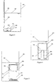
- Figure 2 gives a variant of the previous system characterized in that the drops 220 from piping 209 fall into a receiving cone 221, then into piping 222 of smaller diameter than piping 207. This makes it possible to prevent the fluid coming from R1 does not stagnate above the fluid sucked in 207 during the R2 filling phase. Its arrival in the R2 tank would then be postponed during emptying. On the contrary, using this tube 222, the levels 212 and 223 in the tubes 207 and 222 being almost identical when the densities of the fluids 203 and 204 are close, the transit time of the fluid 203 towards the end 224 of the tube 222 will be much faster than in the previous case.
- the gear ratio of descent between the present case and the case of Figure 2 is equal to s / s ', s and s' being respectively the ratios of the sections of the useful part of the piping 207 to that of the piping 222.
- the fluid to be metered can therefore arrive very quickly in R2.
- FIG. 3 represents a dispenser intended for injecting a dose of a liquid saturated in a product dissolved from a solid matter each time an R2 tank (402) is drained.
- the liquid saturated with dissolved product 404 is contained in a tank R1 (401) provided a small orifice 403 at its upper part.
- R1 contains SS 405 which keep the liquid 404 in saturated state whatever the variations of temperature.
- This small tank R1 is also provided with a large piping length 406, the open top of which is located above the top level of the tank.
- the section of this piping 406 is denoted s.
- R1 Before filling R2, it is assumed that R1 is filled with a saturated liquid whose high level is that of port 403.
- level 407 in R2 goes up as well as level 408 in tube 406. These levels are equal if we neglect the effects of surface tension and close to each other otherwise.
- liquid from R2 enters R1. This liquid mixes with the liquid already present in R1 and becomes saturated in the material dissolved.
- R2 emptying occurs, the level drops in R2 and in the tube 406. Liquid is therefore ejected from R1 and mixes with the liquid contained in R2.
- FIG. 4 represents a dispenser intended for injecting a dose of a liquid saturated in a product dissolved from a solid matter each time an R2 tank (502) is drained.
- the liquid saturated with product below 504 is contained in a tank R1 (501) provided a small opening 503 at its upper part.
- R1 contains soluble materials 505 which allow to keep the liquid 504 in saturated state whatever the variations of temperature.
- This small tank R1 is also provided with a tank 506, the summit is closed.
- This tank 506 contains air provided that the orifice 503 is disposed at the base of said tank 506.
- R1 is filled with a saturated liquid whose high level is that of port 503.
- level 507 in R2 rises as well as the level and pressure in the tank 506 due to the compressibility of gases.
- liquid from R2 enters R1. This liquid mixes with the liquid already present in R1 and saturates in the dissolved matter.
- R2 emptying occurs, the level drops in R2 and in tank 506. Saturated liquid is therefore ejected from R1 and mixes with the liquid contained in R2.
- This system is therefore also a particularly simple way to introduce a flow of a liquid saturated with material dissolved proportional to a main flow. Accuracy of the volume ratio transferred during a drain can be quite excellent.
- This system constitutes therefore, like the system described in FIG. 4, an inexpensive dosing device, precise and particularly reliable.
- FIG. 5 represents a variant of the solution represented in FIG. 4 in which the air contained in R2 is placed in a flexible envelope 510, which allows to prevent it from dissolving in the liquid contained in said reservoir.
- the orifice 503 of communication of R2 with the fluid contained in the tank R1 502 is placed indifferently in the upper, lower or lateral part of the tank as it is the case on figure 6. This tank can possibly undergo azimuthal position changes without losing its effectiveness.
Landscapes
- Engineering & Computer Science (AREA)
- Public Health (AREA)
- General Physics & Mathematics (AREA)
- Automation & Control Theory (AREA)
- Health & Medical Sciences (AREA)
- Physics & Mathematics (AREA)
- Epidemiology (AREA)
- Life Sciences & Earth Sciences (AREA)
- Hydrology & Water Resources (AREA)
- Water Supply & Treatment (AREA)
- Feeding, Discharge, Calcimining, Fusing, And Gas-Generation Devices (AREA)
- Loading And Unloading Of Fuel Tanks Or Ships (AREA)
- Devices For Dispensing Beverages (AREA)
Claims (7)
- Vorrichtung zum Ausgeben eines genau bemessenen Volumens einer ersten Flüssigkeit (203, 404, 504) von einem Hilfsbehälter (201, 401, 501) in einen Hauptbehälter (202, 402, 502), der eine zweite Flüssigkeit (204) enthält und mit Einrichtungen zum Steuern der Zyklen des Füllens und des Leerens der besagten zweiten Flüssigkeit versehen ist, dadurch gekennzeichnet, daß der Hauptbehälter (202, 402, 502) und der Hilfsbehälter (201, 401, 501) dazwischen eine Verbindungsöffnung (211, 403, 503) aufweisen und daß der Hilfsbehälter ein Bemessungselement (207, 406, 506), das eine im wesentlichen vertikale Richtung hat und ein unteres Ende und ein oberes Ende aufweist, welches untere Ende des Bemessungselementes mit dem Hauptbehälter (202, 402, 502) verbunden ist, damit die erste oder die zweite Flüssigkeit in das Bemessungselement bis auf eine Höhe in Abhängigkeit von der Höhe der zweiten Flüssigkeit in dem Hauptbehälter während des Füllens des Hauptbehälters eintreten kann, indem die erste Flüssigkeit über die Verbindungsöffnung zum Hilfsbehälter fließt, und Einrichtungen zum Steuern des Austritts eines Volumens der besagten ersten Flüssigkeit während einer Entleerungsphase des Hauptbehälters aus dem Hilfsbehälter im wesentlichen gleich dem Volumen der ersten oder der zweiten Flüssigkeit, die in das Bemessungelement eingetreten ist, indem die zweite Flüssigkeit über die Verbindungsöffnung zum Hauptbehälter fließt, umfasst.
- Vorrichtung nach Anspruch 1, dadurch gekennzeichnet, daß das Bemessungselement (207) ein rohrförmiges Element ist, dessen unteres Ende im Hauptbehälter (202) mündet, und daß die Einrichtungen, die für den Austritt des Volumens der ersten Flüssigkeit sorgen, Einrichtungen umfassen, die einen Siphon (208, 209) bilden, dessen erstes Ende dicht mit dem oberen Ende des rohrförmigen Elementes verbunden ist und dessen anderes Ende im besagten Hilfsbehälter (201) mündet.
- Vorrichtung nach Anspruch 2, dadurch gekennzeichnet, daß das zweite Ende (201) der Einrichtungen, die einen Siphon (208, 209) bilden, im Hilfsbehälter (201) unter der freien Höhe der ersten Flüssigkeit (203) mündet und daß der Hilfsbehälter (201) an seinem oberen Teil offen ist, so daß während der Phase des Füllens des Hauptbehälters (202) die zweite Flüssigkeit in das rohrförmige Element (207) eintritt und darin ein gleiches Luftvolumen verdrängt und während der Phase des Leerens der aufgrund eines Absinkens der zweiten Flüssigkeit (204) durch das rohrförmige Element erzeugte Hohlraum zu einem Ansaugen eines Austritts mit gleichem Volumen der ersten Flüssigkeit (203) vom Hilfsbehälter (201) in das rohrförmige Element sorgt.
- Vorrichtung nach Anspruch 1, dadurch gekennzeichnet, daß der Hilfsbehälter (401, 501) an seinem oberen Teil mit dem Hauptbehälter über eine Öffnung mit reduziertem Querschnitt (403, 503) verbunden ist, daß der Hilfsbehälter ein Material (405, 505) enthält, das kombiniert mit der zweiten Flüssigkeit, die durch den besagten Behälter hindurchgeht, dazu führt, daß die erste Flüssigkeit (404, 504) abgegeben wird, und daß das untere Ende des Bemessungselementes (406) im Hilfsbehälter mündet, so daß das Bemessungselement die erste Flüssigkeit (404), die vom Hilfsbehälter kommt, aufnehmen kann.
- Vorrichtung nach Anspruch 4, dadurch gekennzeichnet, daß das obere Ende des Bemessungselementes (406, 506) verschlossen ist, so daß während des Anstiegs der zweiten Flüssigkeit im Hauptbehälter diese in den Hilfsbehälter (401, 501) eintritt, indem sie sich in die erste Flüssigkeit umwandelt, und in das Bemessungselement (406, 506) eintritt, indem sie die darin enthaltene Luft komprimiert, und zwar bis auf eine Höhe in Abhängigkeit von der freien Höhe (407, 507) der zweiten Flüssigkeit im Hauptbehälter.
- Vorrichtung nach Anspruch 5, dadurch gekennzeichnet, daß die Luft (508), die im Bemessungselement enthalten ist, in einer dichten verformbaren Hülle (510) eingeschlossen ist.
- Vorrichtung nach Anspruch 4, dadurch gekennzeichnet, daß das Bemessungselement (406) ein rohrförmiges Element ist, dessen zweites oberes Ende offen und auf einer Höhe über der freien Höhe (407) der zweiten Flüssigkeit im Hauptbehälter angeordnet ist, wenn der besagte Behälter gefüllt ist.
Applications Claiming Priority (3)
| Application Number | Priority Date | Filing Date | Title |
|---|---|---|---|
| FR9604126 | 1996-03-27 | ||
| FR9604126A FR2746915A1 (fr) | 1996-03-27 | 1996-03-27 | Dispositifs destines a doser des fluides sous l'effet de changements de niveau |
| PCT/FR1997/000494 WO1997036218A1 (fr) | 1996-03-27 | 1997-03-20 | Dispositifs destines a doser des fluides sous l'effet de changements de niveau |
Publications (2)
| Publication Number | Publication Date |
|---|---|
| EP0890145A1 EP0890145A1 (de) | 1999-01-13 |
| EP0890145B1 true EP0890145B1 (de) | 2001-11-07 |
Family
ID=9490824
Family Applications (1)
| Application Number | Title | Priority Date | Filing Date |
|---|---|---|---|
| EP97915526A Expired - Lifetime EP0890145B1 (de) | 1996-03-27 | 1997-03-20 | Vorrichtung zum dosieren von flüssigkeiten unter einwirkung von füllstandsänderungen |
Country Status (6)
| Country | Link |
|---|---|
| US (1) | US6119281A (de) |
| EP (1) | EP0890145B1 (de) |
| AU (1) | AU2296997A (de) |
| DE (1) | DE69708072D1 (de) |
| FR (1) | FR2746915A1 (de) |
| WO (1) | WO1997036218A1 (de) |
Families Citing this family (6)
| Publication number | Priority date | Publication date | Assignee | Title |
|---|---|---|---|---|
| US10907640B2 (en) | 2016-02-16 | 2021-02-02 | Apgn Inc. | Gas turbine blower/pump |
| IL285305A (en) * | 2021-08-02 | 2023-03-01 | Cohen Nissim | A universal self-cleaning system for toilets and the methods thereof |
| WO2023053424A1 (ja) * | 2021-09-30 | 2023-04-06 | 小林製薬株式会社 | 薬液供給装置 |
| WO2023053427A1 (ja) * | 2021-09-30 | 2023-04-06 | 小林製薬株式会社 | 薬液供給装置 |
| WO2023053425A1 (ja) * | 2021-09-30 | 2023-04-06 | 小林製薬株式会社 | 薬液供給装置 |
| CN117795168A (zh) * | 2021-09-30 | 2024-03-29 | 小林制药株式会社 | 药液供给装置 |
Family Cites Families (14)
| Publication number | Priority date | Publication date | Assignee | Title |
|---|---|---|---|---|
| US1144525A (en) * | 1913-12-09 | 1915-06-29 | William F Rogers | Diffusing apparatus. |
| US1175032A (en) * | 1914-04-01 | 1916-03-14 | Edward R Williams | Method of disinfecting or deodorizing flushing-tanks. |
| US1623132A (en) * | 1925-02-04 | 1927-04-05 | Pennell Reginald Humphrey Lee | Apparatus for mixing and delivering liquids |
| US1728737A (en) * | 1927-07-27 | 1929-09-17 | Lewis D Stoner | Automatic fluid feeder |
| DE624731C (de) * | 1935-02-07 | 1936-01-27 | Josef Eisner | Mischregler |
| US3806965A (en) * | 1971-10-18 | 1974-04-30 | Braun Co W | Liquid dispensing and metering device which also forms a closure for the container |
| US4186856A (en) * | 1978-08-14 | 1980-02-05 | The Procter & Gamble Company | Self-priming passive dosing dispenser |
| US4209864A (en) * | 1978-11-07 | 1980-07-01 | International Flavors & Fragrances Inc. | Cleanser and/or sanitizer and aroma emitting attachment for toilets and process for using same |
| FI64831C (fi) * | 1981-08-14 | 1984-01-10 | Vesiniksi Insinoeoeritoimisto | Anordning foer dosering i bestaemd proportion och snabblandning av utfaellningskemikalier foer rening av avfallsvatten i avfall |
| US4375109A (en) * | 1982-02-22 | 1983-03-01 | The Drackett Company | Passive dispenser having a double air vent system |
| US4459710A (en) * | 1982-10-18 | 1984-07-17 | The Drackett Company | Passive dispenser |
| US4453278A (en) * | 1983-01-06 | 1984-06-12 | Knomark, Inc. | Chemical dispenser |
| US4485500A (en) * | 1983-01-06 | 1984-12-04 | Knomark, Inc. | Gas binding resistant chemical dispenser |
| CA2095806A1 (en) * | 1992-05-12 | 1993-11-13 | Daniel N. Campau | Liquid dispensing apparatus and method |
-
1996
- 1996-03-27 FR FR9604126A patent/FR2746915A1/fr not_active Withdrawn
-
1997
- 1997-03-20 AU AU22969/97A patent/AU2296997A/en not_active Abandoned
- 1997-03-20 DE DE69708072T patent/DE69708072D1/de not_active Expired - Lifetime
- 1997-03-20 EP EP97915526A patent/EP0890145B1/de not_active Expired - Lifetime
- 1997-03-20 WO PCT/FR1997/000494 patent/WO1997036218A1/fr not_active Ceased
- 1997-03-20 US US09/155,330 patent/US6119281A/en not_active Expired - Fee Related
Also Published As
| Publication number | Publication date |
|---|---|
| WO1997036218A1 (fr) | 1997-10-02 |
| FR2746915A1 (fr) | 1997-10-03 |
| US6119281A (en) | 2000-09-19 |
| DE69708072D1 (de) | 2001-12-13 |
| EP0890145A1 (de) | 1999-01-13 |
| AU2296997A (en) | 1997-10-17 |
Similar Documents
| Publication | Publication Date | Title |
|---|---|---|
| FR2508322A1 (fr) | Dispositif et procede de dosage precis de liquides a administrer par voie intraveineuse a un patient | |
| EP0890145B1 (de) | Vorrichtung zum dosieren von flüssigkeiten unter einwirkung von füllstandsänderungen | |
| EP1146007A1 (de) | Flüssigkeitsspender mit Flusssteuerung | |
| WO2000025644A1 (fr) | Cafetiere goutte-a-goutte comportant un dispositif de traitement d'eau | |
| FR2518138A1 (fr) | Machine a laver le linge ou a laver la vaisselle, avec un dispositif de dosage | |
| WO2004017028A1 (fr) | Doseur destine a deverser une dose par inclinaison d'un recipient | |
| FR2622562A1 (fr) | Appareil distributeur de boisson, notamment carbonatee, en micro-gravite | |
| FR2506453A1 (fr) | Procede et dispositif pour la determination et l'introduction d'une masse predeterminee de liquide dans un reservoir | |
| GB2198484A (en) | Syphons and liquid metering devices | |
| EP0341149B1 (de) | Kompensationeinrichtung durch Abfluss einer bestimmten Ersatzflüssigkeit und Anwendung zur Wiederbelieferung eines hydraulischen Kreises | |
| BE503692A (de) | ||
| FR2739170A1 (fr) | Reservoir hydropneumatique anti-belier avec dispositif d'admission et de regulation d'air, procede d'admission d'air | |
| BE523963A (de) | ||
| FR2794238A1 (fr) | Dispositif pour la mesure cyclique d'un debit | |
| FR2808897A1 (fr) | Dispositif de distribution automatique d'une solution chimique destine a etre place dans un reservoir | |
| RU2254448C1 (ru) | Устройство для дозированной подачи химического реагента | |
| EP0102105A2 (de) | Anlage für Volumendosierung | |
| FR2730309A1 (fr) | Procede et dispositif de controle de detecteurs de niveau eleve dans des reservoirs de stockage pour liquides | |
| WO2014001656A2 (fr) | Dispositif de chasse automatique pour reguler le fonctionnement d'un drain siphon | |
| RU1776769C (ru) | Дозатор реагента дл нефт ных скважин | |
| FR2580397A1 (fr) | Detecteur volumetrique de fuite hors de, ou vers, l'enceinte d'une cuve | |
| BE497415A (de) | ||
| FR2606899A1 (fr) | Dispositif de dosage d'un liquide de traitement dans une cuve | |
| BE409274A (de) | ||
| CH284349A (fr) | Distributeur de liquide à séparateur d'air et compteur volumétrique. |
Legal Events
| Date | Code | Title | Description |
|---|---|---|---|
| PUAI | Public reference made under article 153(3) epc to a published international application that has entered the european phase |
Free format text: ORIGINAL CODE: 0009012 |
|
| 17P | Request for examination filed |
Effective date: 19980923 |
|
| AK | Designated contracting states |
Kind code of ref document: A1 Designated state(s): CH DE DK ES FR GB IT LI NL |
|
| 17Q | First examination report despatched |
Effective date: 19990413 |
|
| GRAG | Despatch of communication of intention to grant |
Free format text: ORIGINAL CODE: EPIDOS AGRA |
|
| GRAG | Despatch of communication of intention to grant |
Free format text: ORIGINAL CODE: EPIDOS AGRA |
|
| GRAH | Despatch of communication of intention to grant a patent |
Free format text: ORIGINAL CODE: EPIDOS IGRA |
|
| RAP1 | Party data changed (applicant data changed or rights of an application transferred) |
Owner name: LECOFFRE, YVES |
|
| RIN1 | Information on inventor provided before grant (corrected) |
Inventor name: LECOFFRE, YVES Inventor name: TOURNASSAT, CLAUDE |
|
| GRAH | Despatch of communication of intention to grant a patent |
Free format text: ORIGINAL CODE: EPIDOS IGRA |
|
| GRAA | (expected) grant |
Free format text: ORIGINAL CODE: 0009210 |
|
| AK | Designated contracting states |
Kind code of ref document: B1 Designated state(s): CH DE DK ES FR GB IT LI NL |
|
| PG25 | Lapsed in a contracting state [announced via postgrant information from national office to epo] |
Ref country code: NL Free format text: LAPSE BECAUSE OF FAILURE TO SUBMIT A TRANSLATION OF THE DESCRIPTION OR TO PAY THE FEE WITHIN THE PRESCRIBED TIME-LIMIT Effective date: 20011107 Ref country code: IT Free format text: LAPSE BECAUSE OF FAILURE TO SUBMIT A TRANSLATION OF THE DESCRIPTION OR TO PAY THE FEE WITHIN THE PRE;WARNING: LAPSES OF ITALIAN PATENTS WITH EFFECTIVE DATE BEFORE 2007 MAY HAVE OCCURRED AT ANY TIME BEFORE 2007. THE CORRECT EFFECTIVE DATE MAY BE DIFFERENT FROM THE ONE RECORDED.SCRIBED TIME-LIMIT Effective date: 20011107 Ref country code: GB Free format text: LAPSE BECAUSE OF FAILURE TO SUBMIT A TRANSLATION OF THE DESCRIPTION OR TO PAY THE FEE WITHIN THE PRESCRIBED TIME-LIMIT Effective date: 20011107 |
|
| REG | Reference to a national code |
Ref country code: CH Ref legal event code: EP |
|
| REF | Corresponds to: |
Ref document number: 69708072 Country of ref document: DE Date of ref document: 20011213 |
|
| REG | Reference to a national code |
Ref country code: GB Ref legal event code: IF02 |
|
| PG25 | Lapsed in a contracting state [announced via postgrant information from national office to epo] |
Ref country code: DK Free format text: LAPSE BECAUSE OF FAILURE TO SUBMIT A TRANSLATION OF THE DESCRIPTION OR TO PAY THE FEE WITHIN THE PRESCRIBED TIME-LIMIT Effective date: 20020207 |
|
| PG25 | Lapsed in a contracting state [announced via postgrant information from national office to epo] |
Ref country code: DE Free format text: LAPSE BECAUSE OF FAILURE TO SUBMIT A TRANSLATION OF THE DESCRIPTION OR TO PAY THE FEE WITHIN THE PRESCRIBED TIME-LIMIT Effective date: 20020208 |
|
| PGFP | Annual fee paid to national office [announced via postgrant information from national office to epo] |
Ref country code: FR Payment date: 20020313 Year of fee payment: 6 |
|
| PG25 | Lapsed in a contracting state [announced via postgrant information from national office to epo] |
Ref country code: LI Free format text: LAPSE BECAUSE OF NON-PAYMENT OF DUE FEES Effective date: 20020331 Ref country code: CH Free format text: LAPSE BECAUSE OF NON-PAYMENT OF DUE FEES Effective date: 20020331 |
|
| NLV1 | Nl: lapsed or annulled due to failure to fulfill the requirements of art. 29p and 29m of the patents act | ||
| GBV | Gb: ep patent (uk) treated as always having been void in accordance with gb section 77(7)/1977 [no translation filed] |
Effective date: 20011107 |
|
| PG25 | Lapsed in a contracting state [announced via postgrant information from national office to epo] |
Ref country code: ES Free format text: LAPSE BECAUSE OF FAILURE TO SUBMIT A TRANSLATION OF THE DESCRIPTION OR TO PAY THE FEE WITHIN THE PRESCRIBED TIME-LIMIT Effective date: 20020530 |
|
| PLBE | No opposition filed within time limit |
Free format text: ORIGINAL CODE: 0009261 |
|
| STAA | Information on the status of an ep patent application or granted ep patent |
Free format text: STATUS: NO OPPOSITION FILED WITHIN TIME LIMIT |
|
| 26N | No opposition filed | ||
| REG | Reference to a national code |
Ref country code: CH Ref legal event code: PL |
|
| PG25 | Lapsed in a contracting state [announced via postgrant information from national office to epo] |
Ref country code: FR Free format text: LAPSE BECAUSE OF NON-PAYMENT OF DUE FEES Effective date: 20031127 |
|
| REG | Reference to a national code |
Ref country code: FR Ref legal event code: ST |