EP0889802B1 - Vehicule a feu de signalisation supplementaire - Google Patents
Vehicule a feu de signalisation supplementaire Download PDFInfo
- Publication number
- EP0889802B1 EP0889802B1 EP98906898A EP98906898A EP0889802B1 EP 0889802 B1 EP0889802 B1 EP 0889802B1 EP 98906898 A EP98906898 A EP 98906898A EP 98906898 A EP98906898 A EP 98906898A EP 0889802 B1 EP0889802 B1 EP 0889802B1
- Authority
- EP
- European Patent Office
- Prior art keywords
- additional signalling
- control signal
- signalling light
- light
- vehicle according
- Prior art date
- Legal status (The legal status is an assumption and is not a legal conclusion. Google has not performed a legal analysis and makes no representation as to the accuracy of the status listed.)
- Expired - Lifetime
Links
- 230000001360 synchronised effect Effects 0.000 claims description 5
- 230000011664 signaling Effects 0.000 claims 12
- 230000003213 activating effect Effects 0.000 claims 1
- 239000003990 capacitor Substances 0.000 description 14
- 230000004048 modification Effects 0.000 description 3
- 238000012986 modification Methods 0.000 description 3
- 238000011161 development Methods 0.000 description 2
- 230000018109 developmental process Effects 0.000 description 2
- 230000001105 regulatory effect Effects 0.000 description 2
- 230000033764 rhythmic process Effects 0.000 description 2
- 230000000903 blocking effect Effects 0.000 description 1
- 230000015556 catabolic process Effects 0.000 description 1
- 230000001419 dependent effect Effects 0.000 description 1
- 238000010586 diagram Methods 0.000 description 1
- 230000000694 effects Effects 0.000 description 1
- 230000003287 optical effect Effects 0.000 description 1
- 230000001960 triggered effect Effects 0.000 description 1
Images



Classifications
-
- B—PERFORMING OPERATIONS; TRANSPORTING
- B60—VEHICLES IN GENERAL
- B60Q—ARRANGEMENT OF SIGNALLING OR LIGHTING DEVICES, THE MOUNTING OR SUPPORTING THEREOF OR CIRCUITS THEREFOR, FOR VEHICLES IN GENERAL
- B60Q1/00—Arrangement of optical signalling or lighting devices, the mounting or supporting thereof or circuits therefor
- B60Q1/26—Arrangement of optical signalling or lighting devices, the mounting or supporting thereof or circuits therefor the devices being primarily intended to indicate the vehicle, or parts thereof, or to give signals, to other traffic
- B60Q1/30—Arrangement of optical signalling or lighting devices, the mounting or supporting thereof or circuits therefor the devices being primarily intended to indicate the vehicle, or parts thereof, or to give signals, to other traffic for indicating rear of vehicle, e.g. by means of reflecting surfaces
- B60Q1/302—Arrangement of optical signalling or lighting devices, the mounting or supporting thereof or circuits therefor the devices being primarily intended to indicate the vehicle, or parts thereof, or to give signals, to other traffic for indicating rear of vehicle, e.g. by means of reflecting surfaces mounted in the vicinity, e.g. in the middle, of a rear window
Definitions
- the invention relates to a motor vehicle with an additional signal lamp, especially a raised tail light.
- Elevated rear lights are known from DE-A1-3 133 307.
- US-A-5 119 067 is a vehicle with a raised one Rear light.
- This vehicle has a photocell and for as long as it stays at night another vehicle is irradiated with high beam of a predetermined intensity, this additional tail light flashes with increased frequency and with green or blue light to switch the other vehicle to low beam cause.
- this green or blue signal lights flash which are in the housing of the two Taillights are integrated.
- the object of the invention is to provide a new motor vehicle with improved To provide security features.
- this object is achieved by a motor vehicle with a additional signal light, especially a raised tail light, with a Device for operating this additional signal light with a frequency Hazard warning flasher when a hazard warning signal has been triggered and with a priority device for switching this additional signal light on Operation with a different control signal if such a different control signal from an encoder provided for this purpose on the motor vehicle is generated, which by Automatically exceed a predetermined deceleration of the motor vehicle can be activated.
- a preferred development of the invention is the subject of claim 2. Since at a hazard warning flashing the additional signal light by the occurring conjunctive logic operation is activated, but not when flashing for display the direction of travel, the signal image is improved and the subsequent traffic warned faster so that rear-end collisions can be avoided.
- the frequency of the other control signal is preferably of the frequency of the hazard warning lights different, and in a particularly preferred manner higher than this. Because the exceeding of a predetermined delay of Motor vehicle regularly indicates a special dangerous situation, it is from great advantage, through a particularly striking signal to this extraordinary Point out the dangerous situation and make the approaching traffic special To be careful. This can create a dangerous or emergency situation be clearly distinguished from a breakdown situation.
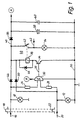
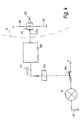
- Fig. 1 shows a right turn signal 10 and a left turn signal 12 one Motor vehicle K (Fig. 2), further an additional signal lamp 14 in the form a rear warning light, which is typical on the rear window of the vehicle is arranged, but naturally also in another suitable place can be arranged.
- the right turn signal lamp 10 receives from an encoder G (FIG. 2) via a line 16 current in the form of current pulses 18, e.g. when the vehicle turns right drives and the driver wants to display that.
- the left turn signal lamp 12 also receives from the transmitter G (FIG. 2) via a line 20 current in the form of current pulses 22, e.g. when operating the turn signal to the left.
- the additional signal lamp 14 may be actuated which is usually in the center of the vehicle as this would confuse subsequent traffic and is therefore inadmissible.
- a hazard warning flash come on both the line 16 and the Line 20 synchronous pulses 18, 22 from a hazard warning light (in G) on, and only in this case should the additional signal lamp 14 be actuated to emit light signals and an additional warning for the to provide subsequent traffic.
- the two inputs of an AND gate are each via a resistor 26, 28 30 connected to lines 16 and 20, so that this AND gate 30 with the simultaneous occurrence of the pulse signals 18, 22 an output signal outputs at its output 31, which is the base of an npn transistor 34 is supplied, whose emitter is connected to the mass 36 of the vehicle. It is connected in series with the coil 38 of a relay 40, the Changeover contact 42 is shown in the de-energized state. Parallel to the coil 38, a free-wheeling diode 44 is connected.
- a diode 46 leads from line 16 to a line 48; one also leads Diode 50 from line 20 to line 48.
- Diode 50 from line 20 to line 48.
- the coil 38 of the relay 40 is between this line 48 and the collector of transistor 34.
- the Series connection of the contact 42 and the third lamp 14 between them Line 48 and ground 36 connected.
- the parallel connection of two capacitors 58, 60 is on via a diode 56 line 48 connected, i.e. if positive impulses 18 and / or 22 pending, these capacitors are charged accordingly. Your negative connections are connected to ground.
- the tension on this Capacitors 58, 60 are connected via a connection A to the positive terminal of the AND gate 30 supplied, the negative terminal in the illustrated Way is connected to ground. This way, as soon as some impulses 18 or 22 have occurred, the AND gate 30 in an operational state Condition kept.
- the capacitor 58 can expediently e.g. a Have a capacity of 1000 ⁇ F.
- the AND gate 30 speaks not on, and the additional signal lamp 14 therefore does not flash.
- the AND gate 30 responds and generates on his Output 31 corresponding pulses that turn on transistor 34 so that the relay 40 receives current from the lines 16, 20 via the diodes 46, 50 and switches the contact 42. This gives the additional signal light 14 a pulsed current and flashes synchronously with the lights 10 and 12th
- the additional signal light 14 can also be connected via a connection 62 Power is supplied to generate other optical signals with it. This is explained below.
- Fig. 3 shows a second embodiment of the invention. Parts which are the same or have the same effect as in the previous figures are usually designated with the same reference symbols as there and are therefore not described again.
- Fig. 3 shows the device, which is designated in Fig. 2 with 70 and the expedient is combined with the additional signal light 14 in one housing.
- the Device 70 has a connection 72 for ground, a connection 74 for a signal 76 from an encoder 78 (Fig. 2), further a connection 80 for a connection with line 16, and a connector 82 for connection to the line 20th
- a diode 84 leads from the terminal 80 and a diode 86 from the terminal 82 a positive supply line 88, the voltage on this line is smoothed by the capacitors 58 and 60 already described
- a resistor 26 likewise leads from the input 80 to a first input and from input 82 a resistor 28 to a second input of a NAND gate 30 ', which in its conjunctive function is the AND gate 30 of FIG. 1st corresponds.
- the inputs of the link 30 ' are as shown connected to ground 36 via RC combinations 88, 90 or 92, 94.
- four diodes 96, 98, 100, 102 are as shown arranged to apply the voltages at the input of the NAND gate 30 ' limit low values.
- the output 30a of the NAND gate 30 ' is connected to one Node 108 connected, which normally, i.e. then when the lamp 14 should not generate a signal, has a high potential. Via a resistor 110 this node 108 is connected to ground 36. He is also with the Input of an inverter 112 connected, the output 112a via a Resistor 114 is connected to the base of npn transistor 34, the has already been described in FIG. 1. If node 108 is high Potential, a low one is obtained at the output of the inverter 112 Potential, and therefore in this case transistor 34 is blocked and that Relay 38 receives no current.
- the relay 38 has two changeover contacts 121, 123, which are shown for the de-energized state of relay 38; in this In this case, the contacts 121, 123 connect the input of the lamp 14 to the Connection 74 so that pulses 76 from a transmitter 78 of the additional Signal light 14 are supplied and this in rhythm with the pulses 76th light up.
- the pulses 76 are also through a resistor 120 and a diode 122 fed to a capacitor 124 and charge it, causing at its positive electrode 125 creates a positive potential, which is via a diode 126 is fed to the node 108 and keeps it positive.
- a high-resistance resistor 128 is provided so that in this If the capacitor 124 is discharged, its positive electrode 125 turns on receives low potential, and consequently the potential at node 108 does not can affect more. In this way you achieve that at The presence of the pulses 76, the relay 38 can not switch and the Pulses 76 are fed directly to the additional signal lamp 14 because node 108 is kept at a positive potential.
- the low potential of node 108 is determined by inverter 112 inverted so that a positive potential is generated at its output 112a which is supplied through resistor 114 to the base of transistor 34 and make it conductive.
- the inverter 112 is likewise designed as a NAND element, the two inputs of which are supplied with the potential at the node 108 at the same time.
- the two NAND elements 30 'and 112 receive their operating voltage from the supply line 88, which can have a potential of +13.8 V, for example.
- Typical values of the components Resistor 120 10 k ⁇ Resistor 128 470 k ⁇ Capacitor 124 1 ⁇ F Transistor 34 BC517 Resistance 114 47 k ⁇ Resistors 26, 28 10 k ⁇ each Resistors 88, 92 100 k ⁇ each Capacitors 90.94 100 nF each Capacitor 58 1000 ⁇ F Capacitor 60 100 nF
- FIG. 4 shows a further circuit which, in the event of a hazard warning flashing, uses the oscillator 160 to actuate the upper signal lamp 14 at a frequency f1 which is different from the frequency f0 of the pulses 18, 22 (FIG. 3) with which the flashing lights 10, 12 are operated.
- the difference between these frequencies f1 and f0 attracts more attention and thereby increases safety in the event of an accident.
- the circuit part to the right of the inverter 112 corresponds to FIG. 3 and has been therefore not shown again.
- the output 112a of the inverter 112 output signals occur, these cause the Oscillator 160, and this then actuates f1 with its output pulses Relay 162, whose switch 164 is in the circuit of the raised lamp 14 lies.
- the frequency f1 is preferably higher than the frequency f0 des Hazard warning flasher, because then the raised lamp 14 is particularly strong stands out and thereby prevents rear-end collisions particularly safely.
- Contact 164 can also be the solution according to FIG. 3 with the two Switching contacts 121, 123 can be used with advantage. For simplification this variant is not shown in FIG. 4.
- the oscillator 160 receives no Input signal more so that it no longer emits pulses f1 and consequently the upper warning light 14 is no longer actuated.
- the generation of the pulses 76 is preferably by a controlled delay-dependent switch that turns on these pulses, when the deceleration of the vehicle K is a predetermined value exceeds.
- This value is preferably a function of whether the vehicle drives uphill or downhill, i.e. the value when driving in the plane is greater than the value when driving uphill, but less than the value when driving downhill.
- Fig. 5 shows a modification to Fig. 3, and therefore the same or equivalent parts as in Fig. 3 are given the same reference numerals as there and are usually not described again.
- the NAND gate 30 controls with its output signal via one Resistor 168 a pnp transistor 170, which is via a voltage regulator 172 (e.g. 78L05) a regulated supply voltage, e.g. + 5 V, from one Positive lead 174 (e.g. +12 V from the vehicle battery) is supplied.
- Capacitors 176 (220 nF), 178 (100 nF) and 180 (47 ⁇ F) serve as Sieve members.
- the regulated voltage is on a line 182 to which the Emitter of transistor 170 is connected, likewise, via a resistor 184, its base.
- Transistor 170 controls the power supply to one Oscillator 186, here in the form of the IC NE 555, the wiring of which is shown in FIG. 5 emerges clearly.
- Oscillator 186 here in the form of the IC NE 555, the wiring of which is shown in FIG. 5 emerges clearly.
- a signal is received desired frequency, e.g. at 120 pulses per minute, and this signal is supplied via resistor 114 to the base of npn transistor 34, whose collector is connected to the positive line 174 via the relay 38.
- the relay 38 controls the raised flashing light 14 via its contact.
- a manually operable contact 192 is on one side with the line 182 and on the other hand via a resistor 194 with a Junction 196 connected. From this leads a first diode 198 upper input 30a of the AND gate 30 ', and a second diode 200 for lower input 30b of the AND gate 30 '.
- diodes 198, 200 receive both inputs 30a, 30b a positive ("high") signal, which one Hazard warning signal corresponds.
- the NAND gate 30 'then produces on its Output 30c has a low potential, and transistor 140 switches the Oscillator 186, whereby the raised warning light 14 with the Frequency of the oscillator 186 is switched off and on, e.g. 120 times in the minute, i.e. with a frequency f1 of 2 Hz.
- the capacitors 90, 94 cause here that the switching element 30 'remains activated as long as these pulses 18, 22 are supplied.
- the raised warning light 14 are operated at a frequency f1, the flashing frequency f0 Lights 10 and 12 is different, and the light 14 can also be used of the switch 192 can be switched on separately.
- the switch 192 can e.g. can also be a switch, which with a corresponding delay of the Vehicle is automatically operated to trigger a warning signal.
Landscapes
- Engineering & Computer Science (AREA)
- Mechanical Engineering (AREA)
- Lighting Device Outwards From Vehicle And Optical Signal (AREA)
Claims (9)
- Véhicule automobile comprenant un feu de signalisation supplémentaire (14), en particulier un feu arrière élevé,comprenant également un dispositif (70) permettant d'activer ce feu de signalisation supplémentaire (14) avec la fréquence d'un clignoteur de détresse (G) lorsqu'une signalisation de détresse est enclenchée,et comprenant aussi un dispositif prioritaire pour commuter ce feu de signalisation supplémentaire (14) sur un fonctionnement avec un autre signal de commande (76) lorsqu'un dispositif (78) prévu à cet effet sur le véhicule émet un tel autre signal de commande (76), ce dispositif (78) étant activé automatiquement lorsque le véhicule enregistre une décélération supérieure à une décélération prédeterminée.
- Véhicule selon la revendication 1, dans lequel le dispositif (70) permettant d'activer le feu de signalisation supplémentaire (14) est agencé pour la combinaison conjonctive de signaux clignotants de détresse (18, 22), ces signaux de détresse (18, 22) étant envoyés aux clignotants (10, 12) en cas de déclenchement d'une signalisation de détresse afin de commander le feu de signalisation supplémentaire (14) avec un signal créé par cette combinaison conjonctive.
- Véhicule selon la revendication 2, dans lequel un circuit NON-ET (30') est prévu pour la combinaison conjonctive de signaux clignotants de détresse (18, 22), le signal à la sortie (30a) de ce circuit contrôlant, directement ou indirectement, le feu de signalisation supplémentaire (14) par l'intermédiaire d'un circuit inverseur (112).
- Véhicule selon la revendication 3, dans lequel un signal de commande provenant d'un circuit intégrateur (120, 122, 124) est envoyé à l'entrée (108) du circuit inverseur (112), un signal de commande particulier (76) pour le feu de signalisation supplémentaire (14) étant envoyé au circuit intégrateur afin de bloquer une commande du feu de signalisation supplémentaire (14) par le circuit inverseur (112) lorsque ce signal de commande particulier (76) est présent afin de permettre une commande directe du feu de signalisation supplémentaire (14) par le signal de commande particulier (76).
- Véhicule selon la revendication 4, dans lequel est prévu un relais (38) avec des contacts à permutation (42; 121, 123) permettant, dans l'état hors tension, de commander le feu de signalisation supplémentaire (14) par le signal de commande particulier (76).
- Véhicule selon l'une des revendications précédentes, dans lequel est prévu un relais (38) avec des contacts à permutation (42; 121, 123) qui permettent de commander, dans leur état permuté, donc lorsque le relais (38) est activé, le feu de signalisation supplémentaire (14) par les signaux clignotants de détresse synchronisés (18, 22) envoyés aux clignotants.
- Véhicule selon l'une des revendications précédentes, dans lequel la fréquence (f1) de l'autre signal de commande (76) est différente de la fréquence (f0) du clignoteur de détresse (G).
- Véhicule selon la revendication 7, dans lequel l'autre signal de commande (76) présente une fréquence supérieure (f1) à la fréquence (f0) du clignoteur de détresse (G).
- Véhicule selon l'une des revendications 2 à 5, dans lequel au moins l'un des signaux (18, 22) émis en cas de signalisation de détresse est envoyé à un organe de mémoire capacitif (58, 60) par une diode (56), la tension sur cet organe de mémoire étant envoyée, comme tension de service, à un circuit conjonctif (30; 30') qui commande le feu de signalisation supplémentaire (14), directement ou indirectement, en cas de combinaison conjonctive de signaux de détresse (18, 22).
Applications Claiming Priority (3)
| Application Number | Priority Date | Filing Date | Title |
|---|---|---|---|
| DE29701438 | 1997-01-29 | ||
| DE29701438U | 1997-01-29 | ||
| PCT/EP1998/000471 WO1998032633A1 (fr) | 1997-01-29 | 1998-01-29 | Vehicule a feu de signalisation supplementaire |
Publications (2)
| Publication Number | Publication Date |
|---|---|
| EP0889802A1 EP0889802A1 (fr) | 1999-01-13 |
| EP0889802B1 true EP0889802B1 (fr) | 2001-10-17 |
Family
ID=8035157
Family Applications (1)
| Application Number | Title | Priority Date | Filing Date |
|---|---|---|---|
| EP98906898A Expired - Lifetime EP0889802B1 (fr) | 1997-01-29 | 1998-01-29 | Vehicule a feu de signalisation supplementaire |
Country Status (4)
| Country | Link |
|---|---|
| EP (1) | EP0889802B1 (fr) |
| AT (1) | ATE207019T1 (fr) |
| DE (2) | DE29801460U1 (fr) |
| WO (1) | WO1998032633A1 (fr) |
Families Citing this family (1)
| Publication number | Priority date | Publication date | Assignee | Title |
|---|---|---|---|---|
| DE20009138U1 (de) | 2000-05-20 | 2001-09-27 | Hagmeier, Georg, 73340 Amstetten | Warnvorrichtung |
Family Cites Families (4)
| Publication number | Priority date | Publication date | Assignee | Title |
|---|---|---|---|---|
| DE3133307A1 (de) | 1981-08-22 | 1983-03-10 | Horst 6600 Saarbrücken Rütz | Zusaetzliche fahrtrichtungsanzeiger |
| US5119067A (en) * | 1990-06-06 | 1992-06-02 | Robert Adell | Rear vehicle courtesy bright light dimming signal system |
| US5237306A (en) * | 1991-12-13 | 1993-08-17 | Robert Adell | Signalling system for requesting a driver of a motor vehicle to dim or turn on his vehicle's headlights |
| FR2743768B1 (fr) * | 1996-01-24 | 1998-02-20 | Safi Mondher | Dispositif pour ameliorer la visibilite des automobilistes en cas de panne ou d'accident sur la route |
-
1998
- 1998-01-29 WO PCT/EP1998/000471 patent/WO1998032633A1/fr not_active Ceased
- 1998-01-29 DE DE29801460U patent/DE29801460U1/de not_active Expired - Lifetime
- 1998-01-29 AT AT98906898T patent/ATE207019T1/de not_active IP Right Cessation
- 1998-01-29 DE DE59801744T patent/DE59801744D1/de not_active Expired - Lifetime
- 1998-01-29 EP EP98906898A patent/EP0889802B1/fr not_active Expired - Lifetime
Also Published As
| Publication number | Publication date |
|---|---|
| WO1998032633A1 (fr) | 1998-07-30 |
| DE29801460U1 (de) | 1998-06-25 |
| DE59801744D1 (de) | 2001-11-22 |
| ATE207019T1 (de) | 2001-11-15 |
| EP0889802A1 (fr) | 1999-01-13 |
Similar Documents
| Publication | Publication Date | Title |
|---|---|---|
| DE10353064B4 (de) | Fahrzeugfahrtrichtungsanzeigesystem und Blinkgeberschaltung für dasselbe | |
| EP0870644B1 (fr) | Feux de véhicule | |
| DE3734449A1 (de) | Vorrichtung zur steuerung eines kraftantriebs fuer fahrzeugfenster | |
| DE4208011C2 (de) | Sicherheitseinrichtung für Kraftfahrzeuge | |
| DE2333789A1 (de) | Beleuchtungssystem fuer ein fahrzeug | |
| DE3724916A1 (de) | Kraftfahrzeug fuer anhaengerbetrieb mit heckleuchten-ueberwachung | |
| DE2920602C2 (de) | Blinkgeber zum Betrieb einer Blinkanlage in Kraftfahrzeugen | |
| DE3630448C1 (de) | Fahrtrichtungsanzeige- und Warnblinkeinrichtung fuer Kraftfahrzeuge | |
| DE102021104086A1 (de) | Sicherheitseinrichtung für wenigstens eine Lichtquelle, Sendeeinrichtung für Licht, Detektionsvorrichtung, Fahrzeug mit wenigstens einer Detektionsvorrichtung und Verfahren zum Betreiben wenigstens einer Lichtquelle | |
| EP0523358B1 (fr) | Circuit pour un système d'alarme d'intrusion ou antivol | |
| EP0889802A1 (fr) | Vehicule a feu de signalisation supplementaire | |
| DE4126762C2 (fr) | ||
| EP3636491A1 (fr) | Lampe de véhicule et son procédé de fonctionnement | |
| EP2564506B1 (fr) | Circuit d'interface et procédé pour influencer la pente d'un signal d'excitation | |
| DE69427777T2 (de) | Lichtsignaleinrichtung | |
| DE202004011221U1 (de) | Kraftfahrzeug-Lampensteuervorrichtung | |
| DE1035074B (de) | Durch eine Lichtquelle steuerbare Schaltvorrichtung | |
| DE2652919A1 (de) | Vorrichtung zur folgegebundenen ansteuerung der beleuchtungseinrichtung eines kraftfahrzeuges | |
| DE102018005663A1 (de) | Glühlampensimulationsschaltung und Verfahren | |
| DE2753528A1 (de) | Ueberwachungsschaltung fuer eine blinkanlage | |
| DE3927496A1 (de) | Schaltungsanordnung fuer motorradscheinwerfer | |
| DE2123793B2 (de) | Elektrische Einrichtung für ein Kraftfahrzeug | |
| EP1157889A2 (fr) | Dispositif avertisseur pour véhicule | |
| DE19841488C2 (de) | Steuereinrichtung für Signalleuchten eines Kraftfahrzeugs | |
| DE19715129C1 (de) | Schaltungsanordnung zur unabhängigen Ansteuerung zweier Verbraucher über eine Leitung |
Legal Events
| Date | Code | Title | Description |
|---|---|---|---|
| PUAI | Public reference made under article 153(3) epc to a published international application that has entered the european phase |
Free format text: ORIGINAL CODE: 0009012 |
|
| 17P | Request for examination filed |
Effective date: 19981028 |
|
| AK | Designated contracting states |
Kind code of ref document: A1 Designated state(s): AT DE FR IT |
|
| 17Q | First examination report despatched |
Effective date: 20000420 |
|
| GRAG | Despatch of communication of intention to grant |
Free format text: ORIGINAL CODE: EPIDOS AGRA |
|
| GRAG | Despatch of communication of intention to grant |
Free format text: ORIGINAL CODE: EPIDOS AGRA |
|
| GRAH | Despatch of communication of intention to grant a patent |
Free format text: ORIGINAL CODE: EPIDOS IGRA |
|
| GRAH | Despatch of communication of intention to grant a patent |
Free format text: ORIGINAL CODE: EPIDOS IGRA |
|
| GRAA | (expected) grant |
Free format text: ORIGINAL CODE: 0009210 |
|
| AK | Designated contracting states |
Kind code of ref document: B1 Designated state(s): AT DE FR IT |
|
| PG25 | Lapsed in a contracting state [announced via postgrant information from national office to epo] |
Ref country code: IT Free format text: LAPSE BECAUSE OF FAILURE TO SUBMIT A TRANSLATION OF THE DESCRIPTION OR TO PAY THE FEE WITHIN THE PRE;WARNING: LAPSES OF ITALIAN PATENTS WITH EFFECTIVE DATE BEFORE 2007 MAY HAVE OCCURRED AT ANY TIME BEFORE 2007. THE CORRECT EFFECTIVE DATE MAY BE DIFFERENT FROM THE ONE RECORDED.SCRIBED TIME-LIMIT Effective date: 20011017 |
|
| REF | Corresponds to: |
Ref document number: 207019 Country of ref document: AT Date of ref document: 20011115 Kind code of ref document: T |
|
| REF | Corresponds to: |
Ref document number: 59801744 Country of ref document: DE Date of ref document: 20011122 |
|
| ET | Fr: translation filed | ||
| PLBE | No opposition filed within time limit |
Free format text: ORIGINAL CODE: 0009261 |
|
| STAA | Information on the status of an ep patent application or granted ep patent |
Free format text: STATUS: NO OPPOSITION FILED WITHIN TIME LIMIT |
|
| 26N | No opposition filed | ||
| PGFP | Annual fee paid to national office [announced via postgrant information from national office to epo] |
Ref country code: AT Payment date: 20091230 Year of fee payment: 13 |
|
| PGFP | Annual fee paid to national office [announced via postgrant information from national office to epo] |
Ref country code: FR Payment date: 20110209 Year of fee payment: 14 |
|
| PG25 | Lapsed in a contracting state [announced via postgrant information from national office to epo] |
Ref country code: AT Free format text: LAPSE BECAUSE OF NON-PAYMENT OF DUE FEES Effective date: 20110129 |
|
| REG | Reference to a national code |
Ref country code: FR Ref legal event code: ST Effective date: 20120928 |
|
| PG25 | Lapsed in a contracting state [announced via postgrant information from national office to epo] |
Ref country code: FR Free format text: LAPSE BECAUSE OF NON-PAYMENT OF DUE FEES Effective date: 20120131 |
|
| PGFP | Annual fee paid to national office [announced via postgrant information from national office to epo] |
Ref country code: DE Payment date: 20130124 Year of fee payment: 16 |
|
| REG | Reference to a national code |
Ref country code: DE Ref legal event code: R119 Ref document number: 59801744 Country of ref document: DE |
|
| REG | Reference to a national code |
Ref country code: DE Ref legal event code: R119 Ref document number: 59801744 Country of ref document: DE Effective date: 20140801 |
|
| PG25 | Lapsed in a contracting state [announced via postgrant information from national office to epo] |
Ref country code: DE Free format text: LAPSE BECAUSE OF NON-PAYMENT OF DUE FEES Effective date: 20140801 |