EP0889757B1 - Antibacterial device for spraying a liquid - Google Patents
Antibacterial device for spraying a liquid Download PDFInfo
- Publication number
- EP0889757B1 EP0889757B1 EP97916509A EP97916509A EP0889757B1 EP 0889757 B1 EP0889757 B1 EP 0889757B1 EP 97916509 A EP97916509 A EP 97916509A EP 97916509 A EP97916509 A EP 97916509A EP 0889757 B1 EP0889757 B1 EP 0889757B1
- Authority
- EP
- European Patent Office
- Prior art keywords
- endpiece
- pump
- liquid
- receptacle
- valve
- Prior art date
- Legal status (The legal status is an assumption and is not a legal conclusion. Google has not performed a legal analysis and makes no representation as to the accuracy of the status listed.)
- Expired - Lifetime
Links
Images


Classifications
-
- B—PERFORMING OPERATIONS; TRANSPORTING
- B05—SPRAYING OR ATOMISING IN GENERAL; APPLYING FLUENT MATERIALS TO SURFACES, IN GENERAL
- B05B—SPRAYING APPARATUS; ATOMISING APPARATUS; NOZZLES
- B05B11/00—Single-unit hand-held apparatus in which flow of contents is produced by the muscular force of the operator at the moment of use
- B05B11/0005—Components or details
-
- A—HUMAN NECESSITIES
- A61—MEDICAL OR VETERINARY SCIENCE; HYGIENE
- A61L—METHODS OR APPARATUS FOR STERILISING MATERIALS OR OBJECTS IN GENERAL; DISINFECTION, STERILISATION OR DEODORISATION OF AIR; CHEMICAL ASPECTS OF BANDAGES, DRESSINGS, ABSORBENT PADS OR SURGICAL ARTICLES; MATERIALS FOR BANDAGES, DRESSINGS, ABSORBENT PADS OR SURGICAL ARTICLES
- A61L2/00—Disinfection or sterilisation of materials or objects, in general; Accessories therefor
- A61L2/16—Disinfection or sterilisation of materials or objects, in general; Accessories therefor using chemical substances
-
- A—HUMAN NECESSITIES
- A61—MEDICAL OR VETERINARY SCIENCE; HYGIENE
- A61M—DEVICES FOR INTRODUCING MEDIA INTO, OR ONTO, THE BODY; DEVICES FOR TRANSDUCING BODY MEDIA OR FOR TAKING MEDIA FROM THE BODY; DEVICES FOR PRODUCING OR ENDING SLEEP OR STUPOR
- A61M15/00—Inhalators
- A61M15/0065—Inhalators with dosage or measuring devices
-
- B—PERFORMING OPERATIONS; TRANSPORTING
- B05—SPRAYING OR ATOMISING IN GENERAL; APPLYING FLUENT MATERIALS TO SURFACES, IN GENERAL
- B05B—SPRAYING APPARATUS; ATOMISING APPARATUS; NOZZLES
- B05B11/00—Single-unit hand-held apparatus in which flow of contents is produced by the muscular force of the operator at the moment of use
- B05B11/0005—Components or details
- B05B11/0037—Containers
- B05B11/0039—Containers associated with means for compensating the pressure difference between the ambient pressure and the pressure inside the container, e.g. pressure relief means
- B05B11/0041—Containers associated with means for compensating the pressure difference between the ambient pressure and the pressure inside the container, e.g. pressure relief means compensating underpressure without contact of the fluid remaining in the container with the atmospheric air
Definitions
- the present invention relates to an antibacterial device for spraying a liquid product.
- the liquid product is contained in a container and the spraying is usually done by a traditional device comprising, in particular, a nozzle intended to cover the spray tube a pump mounted on said container by means of a collar.
- Such a device is described, for example, in the US-A 4,830,284 where said nozzle having an internal conduit extending, on the one hand, the spray tube to an end cavity provided with an ejection orifice, in which a valve is housed, and coaxially surrounded, on the other hand, by a cylindrical-conical outer wall connected in the lower part to a support shoulder for the pump operation.
- Another bacterial protection technique is to incorporate a chemical preservative into the product itself.
- the object of the present invention is to solve the problems previous techniques by combining sealing means mechanical with an antibacterial agent.
- a device for spraying of a liquid product contained in a container comprising in particular a nozzle intended to cap the nozzle of a pump mounted on said container by means of a collar, said end piece comprising an internal conduit extending, on the one hand, the tube nozzle up to an end cavity provided with an ejection orifice, in which is housed a valve, and surrounded coaxially, on the other hand, a cylindrical-conical outer wall connected at the bottom to a support shoulder for operating the pump, characterized in that said internal duct is made with an annular section and around an axial rod while said end cavity is closed and is delimited inside the endpiece by its front wall pierced with the ejection orifice, on the one hand, and through the downstream longitudinal end of said axial rod, on the other hand, and in that all the constituent elements likely to be in contact with the product and in particular the nozzle, are made, at least partially, with a plastic material containing between 0.2% and 2% by weight of a
- said bactericidal agent is a compound containing silver in ionic form.
- the shoulder of the end piece is extended by a lower cylindrical sleeve ensuring, at the same time, the axial guidance of the nozzle in the neck of the container and the end stop stroke on the pump flange.
- said shoulder has a wheelbase greater than outer diameter of the container neck.
- said valve is removable and consisting of a solid cylindrical body, provided at its base with a lip elastically deformable device supported on the walls internal lateral of said cavity and oriented towards the ejection orifice.
- the antibacterial protection is only ensured by mechanical elements and without the chemical composition of the product is not changed.
- the end valve effectively completes the seal of the device, forming an additional protective barrier which is added to the pump valves.
- the bactericidal action is ensured by a chemical agent present in the plastic material constituting the nozzle. This agent is not released into the liquid product and it only acts on contact with said liquid product when it passes through the nozzle, or any other element component of the device, where this agent is present.
- the various valves of the device create as many levels of tightness likely to stop spread before it reaches the while the bactericidal agent completely eliminates the pollution, where it stopped.
- Molding the tip with a plastic material containing a bactericidal agent brings a hygienic function to the device. In Indeed, if the tip is brought into contact with bacterial contamination, it is polluted on the surface. The bactericidal agent present will then destroy the polluting bactericides and keep the tip sterile, preventing any new contamination.
- the present invention therefore results from the combination of mechanical sealing means and chemical bactericidal means.
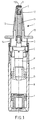
- Figure 1 shows a sectional view of a first mode of production of a device comprising a container R containing a liquid product, a pump P tightly mounted on container R by means of a collar C and equipped with a spray tube G intended to be capped by a nozzle 1.
- the container R comprises, in in addition, a movable bottom F while the foot T of the pump P is equipped a socket D cooperating with the bottom F, to purge the container R.
- the nozzle 1 has an internal conduit 11 extending, the spray tube G, to an end cavity 10, provided with an ejection orifice 100 and in which a valve 2 is housed, as shown in Figures 3a, 3b.
- the internal conduit 11 is surrounded, coaxially, by a wall cylindrical-conical outer 12 connected at the bottom to a shoulder 13 extending transversely and intended for manual support for the pump P operation.
- the shoulder 13 is provided with a lower cylindrical sleeve 14 ensuring, at the same time, the axial guidance of the end piece 1 in the neck of the container R and the end stop on the flange C of the pump P.
- the shoulder 13 has a wheelbase which is greater than the diameter outside of the neck of the container R so as to provide a bearing surface effective.
- the end piece 1 is produced, at least, at the level of the internal walls of conduit 11, cavity 10 and valve 2, in contact with the product, in a plastic material containing a bactericidal agent.
- the end piece 1 can be made entirely with a bactericidal plastic.
- the nozzle is molded by injection or compression, provision may be made for the bactericidal agent to be mixed with the material first before molding.
- the bactericidal agent is preferably a compound containing silver, and for example, silver in ionic form.
- the bactericidal agent acts on contact with the product. It's here For this reason, it is imperative that the zones of the end piece 1 and, the if applicable, the entire spray device, likely to be in contact with the product, contain a quantity sufficient bactericidal agent.
- the quantity considered effective in the field of products considered is between 0.2% and 2% by weight of agent antibacterial in plastic
- such a material makes it possible to regress, logarithmically and within 24 hours, an initial bacterial population of the Staphyloccocus Aureus type from 10 5 to a final population less than 10 2 .
- Figure 2 shows a sectional view of a second variant embodiment, in which the container R contains a flexible pocket deformable S welded to the foot T of the pump P.
- the embodiment of the nozzle 1 is here identical to that of Figures 1 and 3a, 3b.
- the internal conduit 11 is central and axial. It opens at its upper end into the cavity 10 which receives the valve 2 removably.
- the cavity 10 is here open and delimited inside the end piece 1 through the annular rim 101 of the internal conduit 11.
- the valve 2 consists of a solid cylindrical body 20, provided at its base with an elastically deformable peripheral lip 21 which is supported on the internal side walls of the cavity 10.
- the peripheral lip 21 is oriented towards the ejection orifice 100 located at the outlet of the cavity 10.
- the product is pressurized and escapes through the nozzle tube G to the ejection orifice 100, via the internal duct 11, by deforming in the cavity 10, the lip device 21 of valve 2.
- the lip 21 deforms by folding back towards the cylindrical body 20 of the valve 2 and thereby freeing a lateral passage for the product.
- the valve 2 is retained in the cavity 10 by means of a nozzle 3 which closes, at least partially, the mouth of the cavity 10.
- the nozzle 3 has a front face 30 in a bowl pierced with a central orifice for ejecting the product, and a side skirt 31, the lower edge is provided with a latching member in the cavity 10.
- the conduit internal 11 is produced with an annular section and around a rod removable axial 4.
- the cavity 10 is closed and is delimited, inside the nozzle 1, by its front wall pierced with the orifice ejection 100, on the one hand, and by the downstream longitudinal end 4a of the removable axial rod 4, on the other hand.
- the valve 2 is always removable. It is introduced into the cavity 10 by the conduit 11 and is locked in force by the rod 4 against the face internal of the front wall of the end piece 1. If necessary, the rod 4 is secured by its downstream end 4a to the valve 2.
- the end upstream longitudinal 4b of the rod 4 is arranged, in the mounting position of the valve, away from the outlet of the nozzle tube G, so as not to obstruct product exhaust.
Landscapes
- Health & Medical Sciences (AREA)
- Life Sciences & Earth Sciences (AREA)
- Animal Behavior & Ethology (AREA)
- Veterinary Medicine (AREA)
- Engineering & Computer Science (AREA)
- Public Health (AREA)
- General Health & Medical Sciences (AREA)
- Pulmonology (AREA)
- Chemical & Material Sciences (AREA)
- Hematology (AREA)
- Biomedical Technology (AREA)
- Anesthesiology (AREA)
- Bioinformatics & Cheminformatics (AREA)
- Biophysics (AREA)
- Heart & Thoracic Surgery (AREA)
- Chemical Kinetics & Catalysis (AREA)
- General Chemical & Material Sciences (AREA)
- Epidemiology (AREA)
- Containers And Packaging Bodies Having A Special Means To Remove Contents (AREA)
- Apparatus For Disinfection Or Sterilisation (AREA)
- Nozzles (AREA)
- Closures For Containers (AREA)
- Agricultural Chemicals And Associated Chemicals (AREA)
Abstract
Description
La présente invention concerne un dispositif antibactérien de pulvérisation d'un produit liquide.The present invention relates to an antibacterial device for spraying a liquid product.
Le produit liquide est contenu dans un récipient et la pulvérisation est généralement effectuée par un dispositif traditionnel comprenant, notamment, un embout destiné à coiffer le tube gicleur d'une pompe montée sur ledit récipient au moyen d'une collerette.The liquid product is contained in a container and the spraying is usually done by a traditional device comprising, in particular, a nozzle intended to cover the spray tube a pump mounted on said container by means of a collar.
Un tel dispositif est décrit, par exemple, dans le US-A 4 830 284 où ledit embout comportant un conduit interne prolongeant, d'une part, le tube gicleur jusqu'à une cavité d'extrémité pourvue d'un orifice d'éjection, dans laquelle est logé un clapet, et entouré coaxialement, d'autre part, d'une paroi externe cylindro-conique raccordée en partie basse à un épaulement d'appui pour la manoeuvre de la pompe.Such a device is described, for example, in the US-A 4,830,284 where said nozzle having an internal conduit extending, on the one hand, the spray tube to an end cavity provided with an ejection orifice, in which a valve is housed, and coaxially surrounded, on the other hand, by a cylindrical-conical outer wall connected in the lower part to a support shoulder for the pump operation.
Avec de tels dispositifs, la protection anti-bactérienne du produit n'est assurée que par les clapets de la pompe. Cette protection est complétée, le cas échéant, par l'utilisation d'une poche déformable renfermant le produit, et qui est soudée à la pompe, ou d'un récipient de volume variable pourvu d'un fond mobile.With such devices, the anti-bacterial protection of product is only ensured by the pump valves. This protection is supplemented, if necessary, by the use of a deformable pocket containing the product, and which is welded to the pump, or a container of variable volume provided with a movable bottom.
Cependant, ces moyens de protection ne sont pas suffisamment efficaces pour maintenir le conditionnement stérile et pour éviter tout risque de contamination du produit.However, these means of protection are not sufficient effective in maintaining sterile packaging and avoiding any risk of product contamination.
Une autre technique de protection bactérienne consiste à incorporer dans le produit lui-même un conservateur chimique.Another bacterial protection technique is to incorporate a chemical preservative into the product itself.
Mais ces conservateurs sont responsables d'une altération des qualités du produit, en particulier pour des produits pharmaceutiques et cosmétiques où ils génèrent, même parfois, des effets secondaires indésirables pour le consommateur.But these preservatives are responsible for altering the product qualities, especially for pharmaceuticals and cosmetics where they sometimes generate side effects undesirable for the consumer.
La présente invention a pour but de résoudre les problèmes techniques précédents en combinant des moyens d'étanchéité mécaniques avec un agent antibactérien.The object of the present invention is to solve the problems previous techniques by combining sealing means mechanical with an antibacterial agent.
Ce but est atteint selon l'invention par un dispositif de pulvérisation d'un produit liquide contenu dans un récipient, comprenant notamment un embout destiné à coiffer le gicleur d'une pompe montée sur ledit récipient au moyen d'une collerette, ledit embout comportant un conduit interne prolongeant, d'une part, le tube gicleur jusqu'à une cavité d'extrémité pourvue d'un orifice d'éjection, dans laquelle est logé un clapet, et entouré coaxialement, d'autre part, d'une paroi externe cylindre-conique raccordée en partie basse à un épaulement d'appui pour la manoeuvre de la pompe caractérisé en ce que ledit conduit interne est réalisé avec une section annulaire et autour d'une tige axiale tandis que ladite cavité d'extrémité est fermée et est délimitée à l'intérieur de l'embout par sa paroi frontale percée de l'orifice d'éjection, d'une part, et par l'extrémité longitudinale aval de ladite tige axiale, d'autre part, et en ce que tous les éléments constitutifs susceptibles d'être en contact avec le produit et en particulier l'embout, sont réalisés, au moins partiellement, avec une matière plastique contenant entre 0,2% et 2% en poids d'un agent bactéricide qui n'agit que par contact et sans relarguage dans le produit. This object is achieved according to the invention by a device for spraying of a liquid product contained in a container, comprising in particular a nozzle intended to cap the nozzle of a pump mounted on said container by means of a collar, said end piece comprising an internal conduit extending, on the one hand, the tube nozzle up to an end cavity provided with an ejection orifice, in which is housed a valve, and surrounded coaxially, on the other hand, a cylindrical-conical outer wall connected at the bottom to a support shoulder for operating the pump, characterized in that said internal duct is made with an annular section and around an axial rod while said end cavity is closed and is delimited inside the endpiece by its front wall pierced with the ejection orifice, on the one hand, and through the downstream longitudinal end of said axial rod, on the other hand, and in that all the constituent elements likely to be in contact with the product and in particular the nozzle, are made, at least partially, with a plastic material containing between 0.2% and 2% by weight of a bactericidal agent which does not act only by contact and without leaching into the product.
Selon un mode de réalisation particulier, ledit agent bactéricide est un composé contenant de l'argent sous forme ionique.According to a particular embodiment, said bactericidal agent is a compound containing silver in ionic form.
Selon une caractéristique avantageuse, l'épaulement de l'embout se prolonge par un manchon cylindrique inférieur assurant, à la fois, le guidage axial de l'embout dans le col du récipient et la butée de fin de course sur la collerette de la pompe.According to an advantageous characteristic, the shoulder of the end piece is extended by a lower cylindrical sleeve ensuring, at the same time, the axial guidance of the nozzle in the neck of the container and the end stop stroke on the pump flange.
De préférence, ledit épaulement a un empattement supérieur au diamètre extérieur du col du récipient.Preferably, said shoulder has a wheelbase greater than outer diameter of the container neck.
Selon une autre caractéristique, ledit clapet est amovible et constitué d'un corps cylindrique plein, pourvu à sa base d'une lèvre périphérique élastiquement déformable prenant appui sur les parois latérales internes de ladite cavité et orientée vers l'orifice d'éjection. According to another characteristic, said valve is removable and consisting of a solid cylindrical body, provided at its base with a lip elastically deformable device supported on the walls internal lateral of said cavity and oriented towards the ejection orifice.
Avec le dispositif de l'invention, la protection antibactérienne n'est assurée que par des éléments mécaniques et sans que la composition chimique du produit ne soit modifiée.With the device of the invention, the antibacterial protection is only ensured by mechanical elements and without the chemical composition of the product is not changed.
Le clapet d'extrémité complète de manière efficace l'étanchéité du dispositif, en formant une barrière de protection supplémentaire qui vient s'ajouter aux clapets de la pompe.The end valve effectively completes the seal of the device, forming an additional protective barrier which is added to the pump valves.
L'action bactéricide est assurée par un agent chimique présent dans la matière plastique constitutive de l'embout. Cet agent n'est pas relargué dans le produit liquide et il n'agit que par contact avec ledit produit lorsque celui-ci passe dans l'embout, ou dans tout autre élément constitutif du dispositif, où cet agent est présent.The bactericidal action is ensured by a chemical agent present in the plastic material constituting the nozzle. This agent is not released into the liquid product and it only acts on contact with said liquid product when it passes through the nozzle, or any other element component of the device, where this agent is present.
En présence d'une pollution bactérienne, les différents clapets du dispositif (embout, pompe) créent autant de niveaux d'étanchéité susceptibles de stopper la dissémination avant qu'elle n'atteigne le produit, tandis que l'agent bactéricide élimine complètement la pollution, là où elle est arrêtée.In the presence of bacterial pollution, the various valves of the device (nozzle, pump) create as many levels of tightness likely to stop spread before it reaches the while the bactericidal agent completely eliminates the pollution, where it stopped.
Le moulage de l'embout avec une matière plastique contenant un agent bactéricide apporte une fonction hygiénique au dispositif. En effet, si l'embout est mis en contact avec une contamination bactérienne, il est pollué en surface. L'agent bactéricide présent va alors détruire les bactéricides polluantes et maintenir l'embout stérile, en prévenant toute nouvelle contamination.Molding the tip with a plastic material containing a bactericidal agent brings a hygienic function to the device. In Indeed, if the tip is brought into contact with bacterial contamination, it is polluted on the surface. The bactericidal agent present will then destroy the polluting bactericides and keep the tip sterile, preventing any new contamination.
La présente invention résulte donc de la combinaison entre des moyens mécaniques d'étanchéité et des moyens chimiques bactéricides.The present invention therefore results from the combination of mechanical sealing means and chemical bactericidal means.
L'invention sera mieux comprise à la lecture de la description qui va suivre accompagnée des dessins sur lesquels :
- la figure 1 représente une vue en coupe d'un mode de réalisation qui n'est pas couvert par les revendications, mais est conservé à titre d'explication.
- la figure 2 représente une vue en coupe d'une variante du mode de réalisation de la figure 1;
- les figures 3a et 3b représentent, respectivement, des vues, en coupe et de dessus, agrandies du mode de réalisation des figures 1 et 2;
- les figures 4a et 4b représentent, respectivement, des vues, en coupe et de dessus, d'un mode de réalisation de l'invention.
- Figure 1 shows a sectional view of an embodiment which is not covered by the claims, but is kept by way of explanation.
- 2 shows a sectional view of a variant of the embodiment of Figure 1;
- Figures 3a and 3b show, respectively, views, in section and from above, enlarged of the embodiment of Figures 1 and 2;
- Figures 4a and 4b show, respectively, views, in section and from above, of an embodiment of the invention.
La figure 1 représente une vue en coupe d'un premier mode de
réalisation d'un dispositif comprenant un récipient R
contenant un produit liquide, une pompe P montée de façon étanche sur
le récipient R au moyen d'une collerette C et équipée d'un tube gicleur
G destiné à être coiffé par un embout 1. Le récipient R comporte, en
outre, un fond mobile F tandis que le pied T de la pompe P est équipé
d'une douille D coopérant avec le fond F, pour purger le récipient R.Figure 1 shows a sectional view of a first mode of
production of a device comprising a container R
containing a liquid product, a pump P tightly mounted on
container R by means of a collar C and equipped with a spray tube
G intended to be capped by a
De manière générale, l'embout 1 comporte un conduit interne 11
prolongeant, le tube gicleur G, jusqu'à une cavité 10 d'extrémité,
pourvue d'un orifice d'éjection 100 et dans laquelle est logé un clapet 2,
comme représenté sur les figures 3a, 3b.Generally, the
Le conduit interne 11 est entouré, coaxialement, d'une paroi
externe cylindro-conique 12 raccordée en partie basse à un épaulement
13 s'étendant transversalement et destiné à l'appui manuel pour la
manoeuvre de la pompe P.The
L'épaulement 13 est pourvu d'un manchon cylindrique inférieur
14 assurant, à la fois, le guidage axial de l'embout 1 dans le col du
récipient R et la butée de fin de course sur la collerette C de la pompe P.The
L'épaulement 13 a un empattement qui est supérieur au diamètre
extérieur du col du récipient R de façon à offrir une surface d'appui
efficace.The
L'embout 1 est réalisé, au moins, au niveau des
parois internes du conduit 11, de la cavité 10 et du clapet 2, en contact
avec le produit, en une matière plastique contenant un agent bactéricide.The
Bien entendu, l'embout 1 peut être réalisé intégralement avec
une matière plastique bactéricide.Of course, the
Dans le cas où l'embout est moulé par injection ou compression, on peut prévoir que l'agent bactéricide soit mélangé avec la matière première avant le moulage.In the case where the nozzle is molded by injection or compression, provision may be made for the bactericidal agent to be mixed with the material first before molding.
Il est également possible de prévoir que tous les éléments
constitutifs du dispositif (embout 1, corps, piston, et gicleur de la
pompe P, récipient R, collerette C ...) sont réalisés avec une matière
plastique bactéricide de façon à renforcer cette action.It is also possible to provide that all the elements
components of the device (
L'agent bactéricide est de préférence un composé contenant de l'argent, et par exemple, de l'argent sous forme ionique.The bactericidal agent is preferably a compound containing silver, and for example, silver in ionic form.
L'agent bactéricide agit par contact avec le produit. C'est la
raison pour laquelle, il est impératif que les zones de l'embout 1 et, le
cas échéant, du dispositif de pulvérisation dans son ensemble,
susceptibles d'être en contact avec le produit, contiennent une quantité
suffisante d'agent bactéricide.The bactericidal agent acts on contact with the product. It's here
For this reason, it is imperative that the zones of the
La quantité considérée comme efficace dans le domaine des produits considérés est comprise entre 0,2 % et 2% en poids d'agent antibactérien dans la matière plastiqueThe quantity considered effective in the field of products considered is between 0.2% and 2% by weight of agent antibacterial in plastic
A titre d'exemple, une telle matière permet de faire régresser de façon logarithmique et en 24 heures, une population bactérienne initiale du type staphyloccocus Aureus de 105 à une population finale inférieure à 102.By way of example, such a material makes it possible to regress, logarithmically and within 24 hours, an initial bacterial population of the Staphyloccocus Aureus type from 10 5 to a final population less than 10 2 .
La figure 2 représente une vue en coupe d'une seconde variante de réalisation, dans laquelle le récipient R renferme une poche souple déformable S soudée au pied T de la pompe P.Figure 2 shows a sectional view of a second variant embodiment, in which the container R contains a flexible pocket deformable S welded to the foot T of the pump P.
Le mode de réalisation de l'embout 1 est ici identique à celui des
figures 1 et 3a,3b.The embodiment of the
Dans ce mode de réalisation, le conduit interne 11 est
central et axial. Il débouche, à son extrémité supérieure, dans la cavité
10 qui reçoit le clapet 2 de façon amovible.In this embodiment, the
La cavité 10 est ici ouverte et délimitée à l'intérieur de
l'embout 1 par le rebord annulaire 101 du conduit interne 11.The
Le clapet 2 est constitué d'un corps cylindrique plein 20, pourvu
à sa base d'une lèvre périphérique 21 élastiquement déformable qui
prend appui sur les parois latérales internes de la cavité 10.The
La lèvre périphérique 21 est orientée vers l'orifice d'éjection 100
situé au débouché de la cavité 10.The
Par manoeuvre de la pompe P, le produit est mis sous pression
et s'échappe par le tube gicleur G vers l'orifice d'éjection 100, via le
conduit interne 11, en déformant dans la cavité 10, la lèvre
périphérique 21 du clapet 2.By operating pump P, the product is pressurized
and escapes through the nozzle tube G to the
La lèvre 21 se déforme en se rabattant vers le corps cylindrique
20 du clapet 2 et en libérant ainsi un passage latéral pour le produit.The
Le clapet 2 est retenu dans la cavité 10 au moyen d'une buse 3
qui obture, au moins partiellement, l'embouchure de la cavité 10.The
La buse 3 comporte une face frontale 30 en cuvette percée d'un
orifice central pour l'éjection du produit, et une jupe latérale 31, dont le
bord inférieur est pourvu d'un organe d'encliquetage dans la cavité 10. The
Conformément à l'invention, dans le mode de réalisation des figures 4a et 4b, le conduit
interne 11 est réalisé avec une section annulaire et autour d'une tige
axiale amovible 4. Dans ce cas, la cavité 10 est fermée et est délimitée,
à l'intérieur de l'embout 1, par sa paroi frontale percée de l'orifice
d'éjection 100, d'une part, et par l'extrémité longitudinale aval 4a de la
tige axiale amovible 4, d'autre part.According to the invention, in the embodiment of Figures 4a and 4b, the conduit
internal 11 is produced with an annular section and around a rod
removable axial 4. In this case, the
Le clapet 2 est toujours amovible. Il est introduit dans la cavité
10 par le conduit 11 et est bloqué en force par la tige 4 contre la face
interne de la paroi frontale de l'embout 1. Le cas échéant, la tige 4 est
solidaire par son extrémité aval 4a du clapet 2. L'extrémité
longitudinale amont 4b de la tige 4 est disposée, en position de montage
du clapet, à distance du débouché du tube gicleur G, pour ne pas gêner
l'échappement du produit.The
Claims (5)
- An antibacterial spray device for spraying a liquid contained in a receptacle (R), the device comprising, in particular, an endpiece designed to cover the outlet tube (G) of a pump (P) which is mounted on said receptacle (R) by means of a collar (C); said endpiece (1) includes an internal duct (11) which firstly extends from the outlet tube (G) to an end cavity (10) which is provided with an ejection orifice (100), and in which a valve (2) is housed, and secondly, is surrounded coaxially by a tapering cylindrical outside wall (12) which is attached at its bottom portion to a bearing shoulder (13) for operating the pump (P), the device being characterized in that said internal duct (11) is of annular section, about an axial rod (4), while said end cavity (10) is closed and is defined inside the endpiece (1) firstly by its front wall which is pierced by the ejection orifice (100), and secondly by the downstream longitudinal end (4a) of said axial rod (4), and
in that all the component parts that can come into contact with the liquid, and in particular the endpiece (1), are made, at least in part, of a plastics material containing between 0.2% and 2% by weight of a bactericidal agent which acts solely by coming into contact with the liquid but without being released into it. - A device according to claim 1, characterized in that said bactericidal agent is a compound containing silver in ionic form.
- A device according to any preceding claim, characterized in that said shoulder (13) of the endpiece (1) is extended by a bottom cylindrical sleeve (14) which ensures that the endpiece (1) is axially guided inside the neck of the receptacle (R) and comes into abutment with the collar (C) of the pump (P).
- A device according to any preceding claim, characterized in that said shoulder (13) of the endpiece (1) has a span which is greater than the outside diameter of the neck of the receptacle (R).
- A device according to any preceding claim, characterized in that said valve (2) is removable and constituted by a solid cylindrical body (20) provided at its base with an elastically-deformable peripheral lip (21) which bears against the internal side walls of said cavity (10) and is oriented towards the ejection orifice (100).
Applications Claiming Priority (3)
| Application Number | Priority Date | Filing Date | Title |
|---|---|---|---|
| FR9603943A FR2746657B1 (en) | 1996-03-29 | 1996-03-29 | ANTIBACTERIAL DEVICE FOR SPRAYING A LIQUID PRODUCT |
| FR9603943 | 1996-03-29 | ||
| PCT/FR1997/000550 WO1997036690A1 (en) | 1996-03-29 | 1997-03-27 | Antibacterial device for spraying a liquid |
Publications (2)
| Publication Number | Publication Date |
|---|---|
| EP0889757A1 EP0889757A1 (en) | 1999-01-13 |
| EP0889757B1 true EP0889757B1 (en) | 2002-06-12 |
Family
ID=9490699
Family Applications (1)
| Application Number | Title | Priority Date | Filing Date |
|---|---|---|---|
| EP97916509A Expired - Lifetime EP0889757B1 (en) | 1996-03-29 | 1997-03-27 | Antibacterial device for spraying a liquid |
Country Status (10)
| Country | Link |
|---|---|
| US (1) | US6095376A (en) |
| EP (1) | EP0889757B1 (en) |
| JP (1) | JP3946770B2 (en) |
| AT (1) | ATE218926T1 (en) |
| DE (1) | DE69713306T2 (en) |
| DK (1) | DK0889757T3 (en) |
| ES (1) | ES2177968T3 (en) |
| FR (1) | FR2746657B1 (en) |
| PT (1) | PT889757E (en) |
| WO (1) | WO1997036690A1 (en) |
Families Citing this family (33)
| Publication number | Priority date | Publication date | Assignee | Title |
|---|---|---|---|---|
| FR2791955B1 (en) * | 1999-04-09 | 2001-06-22 | Valois Sa | DEVICE FOR SEALING THE DISPENSING PORT OF A FLUID DISPENSER |
| US6382204B1 (en) | 1999-10-14 | 2002-05-07 | Becton Dickinson And Company | Drug delivery system including holder and drug container |
| USD463546S1 (en) | 1999-10-14 | 2002-09-24 | Becton Dickinson And Company | Drug container holder |
| AU2002222066A1 (en) | 2000-11-30 | 2002-06-11 | Cebal Sa | Containers comprising a wall containing biocidal agents |
| DE10200595A1 (en) * | 2002-01-10 | 2003-07-31 | Aero Pump Gmbh | Actuating head of a suction-pressure pump for ejecting a product from a container |
| DE10200593A1 (en) * | 2002-01-10 | 2003-07-31 | Aero Pump Gmbh | Actuating head of a suction-pressure pump for ejecting a product from a container |
| EP1496832A2 (en) * | 2002-04-10 | 2005-01-19 | Disop-Nordic Holding APS | Tube with self-closing mechanism for liquid container |
| GB0302536D0 (en) * | 2003-02-04 | 2003-03-12 | Bespak Plc | Container |
| ATE315962T1 (en) * | 2003-04-09 | 2006-02-15 | Ursapharm Arzneimittel Gmbh | MEDIA DONOR |
| US7249693B2 (en) * | 2003-04-09 | 2007-07-31 | Ursapharm Arzneimittel Gmbh & Co. Kg | Fluid dispenser |
| MXPA05001982A (en) * | 2004-12-22 | 2006-06-21 | Ursapharm Arzneimittel Gmbh | Fluid dispenser. |
| DE102005033771A1 (en) * | 2005-07-15 | 2007-01-25 | Saint-Gobain Calmar Gmbh | Fluidaustragkopf |
| CA2680553A1 (en) * | 2007-03-13 | 2008-09-18 | 0736413 B.C. Ltd. | Disinfectant cap for sterile liquid dispenser |
| DE102007023012B4 (en) * | 2007-05-15 | 2025-04-30 | Boehringer Ingelheim Pharma Gmbh & Co. Kg | atomizer |
| FR2954327B1 (en) | 2009-12-23 | 2012-11-30 | Valois Sas | METHOD FOR SURFACE TREATMENT OF A FLUID PRODUCT DISPENSING DEVICE |
| JP2013534975A (en) | 2010-07-02 | 2013-09-09 | アプター フランス エスアーエス | Surface treatment method for fluid administration device |
| CN113230021A (en) | 2015-01-12 | 2021-08-10 | 科达莱昂治疗公司 | Droplet delivery apparatus and method |
| DE102016204953A1 (en) * | 2016-03-24 | 2017-09-28 | F. Holzer Gmbh | Metering pump for a metering device and metering device |
| US10888454B2 (en) | 2017-01-20 | 2021-01-12 | Kedalion Therapeutics, Inc. | Piezoelectric fluid dispenser |
| AU2018380433B2 (en) | 2017-12-08 | 2024-10-10 | Bausch + Lomb Ireland Limited | Fluid delivery alignment system |
| US12350194B1 (en) | 2018-04-12 | 2025-07-08 | Bausch + Lomb Ireland Limited | Topical ocular delivery of fluids with controlled mass dosing and wireless communication |
| US20190314198A1 (en) | 2018-04-12 | 2019-10-17 | Kedalion Therapeutics, Inc. | Topical Ocular Delivery Methods and Devices for Use in the Same |
| FR3081113B1 (en) * | 2018-05-18 | 2020-05-29 | Albea Le Treport | PISTON FOR TANK OF A DISPENSER OF A FLUID PRODUCT WITHOUT AIR INTAKE |
| AU2019297326B2 (en) | 2018-07-03 | 2025-01-09 | Bausch + Lomb Ireland Limited | Topical ocular delivery devices and methods for using the same |
| WO2020157836A1 (en) * | 2019-01-29 | 2020-08-06 | 株式会社エイエムジー | Sterilization member and cosmetic container |
| US12097145B2 (en) | 2019-03-06 | 2024-09-24 | Bausch + Lomb Ireland Limited | Vented multi-dose ocular fluid delivery system |
| US11679028B2 (en) | 2019-03-06 | 2023-06-20 | Novartis Ag | Multi-dose ocular fluid delivery system |
| US12496218B1 (en) | 2019-11-12 | 2025-12-16 | Bausch + Lomb Ireland Limited | Fractionated topical ocular drug delivery methods and devices for use in the same |
| WO2021212038A1 (en) | 2020-04-17 | 2021-10-21 | Kedalion Therapeutics, Inc. | Hydrodynamically actuated preservative free dispensing system having a collapsible liquid reservoir |
| US12290472B2 (en) | 2020-04-17 | 2025-05-06 | Bausch + Lomb Ireland Limited | Hydrodynamically actuated preservative free dispensing system |
| US11938057B2 (en) | 2020-04-17 | 2024-03-26 | Bausch + Lomb Ireland Limited | Hydrodynamically actuated preservative free dispensing system |
| BR112022020948A2 (en) | 2020-04-17 | 2023-04-11 | Kedallion Therapeutics Inc | HYDRODYNAMICALLY ACTUATED PRESERVATIVE FREE DISTRIBUTION SYSTEM |
| US11937633B1 (en) | 2023-05-25 | 2024-03-26 | Next Level Ventures LLC | Vaping mouthpiece locking structure |
Family Cites Families (9)
| Publication number | Priority date | Publication date | Assignee | Title |
|---|---|---|---|---|
| GB898320A (en) * | 1959-11-24 | 1962-06-06 | Astra Ab | Self-sterilizing packing material and method of producing same |
| CA1166203A (en) * | 1979-12-21 | 1984-04-24 | Luigi Del Bon | Self-sealing actuating device for mounting on a discharge valve of a pressurized container |
| DE3315334A1 (en) * | 1983-04-28 | 1984-10-31 | Pfeiffer Erich Gmbh & Co Kg | SPRAYER OR DOSING PUMP |
| FR2635084B1 (en) * | 1988-08-08 | 1991-04-12 | Sofab | DISTRIBUTOR TIPS |
| FR2654078B1 (en) * | 1989-11-07 | 1992-02-28 | Valois | SHUTTER OF THE OUTPUT CHANNEL OF A DISPENSING HEAD FOR PASTA PRODUCTS AND DISPENSING HEAD ADVANTABLY ASSOCIATED. |
| FR2665848B1 (en) * | 1990-08-17 | 1992-10-30 | Aerosols & Bouchage | INCORPORATED VALVE NOZZLES. |
| FR2671329B1 (en) * | 1991-01-07 | 1993-03-19 | Valois | MULTI-JET PUSH-BUTTON WITH CLOSURE. |
| FR2693991B1 (en) * | 1992-07-21 | 1994-11-25 | Oreal | Distribution assembly for at least one liquid or pasty product, comprising a closure system without air intake and preservation method using said assembly. |
| US5490938A (en) * | 1993-12-20 | 1996-02-13 | Biopolymerix, Inc. | Liquid dispenser for sterile solutions |
-
1996
- 1996-03-29 FR FR9603943A patent/FR2746657B1/en not_active Expired - Fee Related
-
1997
- 1997-03-27 PT PT97916509T patent/PT889757E/en unknown
- 1997-03-27 DE DE69713306T patent/DE69713306T2/en not_active Expired - Fee Related
- 1997-03-27 US US09/147,058 patent/US6095376A/en not_active Expired - Fee Related
- 1997-03-27 WO PCT/FR1997/000550 patent/WO1997036690A1/en not_active Ceased
- 1997-03-27 AT AT97916509T patent/ATE218926T1/en not_active IP Right Cessation
- 1997-03-27 EP EP97916509A patent/EP0889757B1/en not_active Expired - Lifetime
- 1997-03-27 ES ES97916509T patent/ES2177968T3/en not_active Expired - Lifetime
- 1997-03-27 JP JP53497997A patent/JP3946770B2/en not_active Expired - Fee Related
- 1997-03-27 DK DK97916509T patent/DK0889757T3/en active
Also Published As
| Publication number | Publication date |
|---|---|
| DK0889757T3 (en) | 2002-10-07 |
| EP0889757A1 (en) | 1999-01-13 |
| FR2746657A1 (en) | 1997-10-03 |
| ES2177968T3 (en) | 2002-12-16 |
| PT889757E (en) | 2002-11-29 |
| ATE218926T1 (en) | 2002-06-15 |
| DE69713306T2 (en) | 2003-01-09 |
| JP3946770B2 (en) | 2007-07-18 |
| FR2746657B1 (en) | 1998-06-26 |
| US6095376A (en) | 2000-08-01 |
| JP2000509319A (en) | 2000-07-25 |
| DE69713306D1 (en) | 2002-07-18 |
| WO1997036690A1 (en) | 1997-10-09 |
Similar Documents
| Publication | Publication Date | Title |
|---|---|---|
| EP0889757B1 (en) | Antibacterial device for spraying a liquid | |
| EP0549050B1 (en) | Assembly for dispensing at least one fluid product such as cosmetics or pharmaceutics | |
| EP1166885B1 (en) | Dispensing head and a packaging and dispensing unit provided with such a head | |
| EP0874761B1 (en) | Nozzle for dispensing a liquid or pasty material | |
| EP1284827A1 (en) | Diaphragm pump | |
| FR2716873A1 (en) | Apparatus for sealing the contents of a pressurized container or a pump container. | |
| CA2342086C (en) | Air recirculation component, cap fitted with such a component, vessel fitted with such a component or such a cap, and assembly comprising such a component | |
| EP3431188B1 (en) | Dispensing head for product from a container | |
| EP0881158A1 (en) | Device for dispensing and storing sterile fluids | |
| FR2649074A1 (en) | CONTAINER WITH ELASTIC SECTION BOTTLE | |
| EP3034178B1 (en) | Dispensing head for a product dispensing system | |
| FR3023734A1 (en) | DISTRIBUTION HEAD FOR A SYSTEM FOR DISTRIBUTING A PRODUCT | |
| CH618896A5 (en) | ||
| EP2446970B1 (en) | Dispensing system and dispenser for a fluid product dispenser | |
| EP2457667B1 (en) | Dispensing system for dispensing a fluid product | |
| WO2006003297A1 (en) | Simplified airless dispensing pump for liquid products | |
| EP0606783A1 (en) | Droplet forming tip | |
| WO1999034930A1 (en) | Rechargeable spray dispenser | |
| EP1945373B1 (en) | Tilting flap pump | |
| FR2462360A1 (en) | Variable angle aerosol spray nozzle - has two swivel joints in succession, with axes at right angles | |
| FR2884737A1 (en) | RECHARGEABLE FOAM PUMP | |
| FR2543920A1 (en) | Stopper device for a bottle or deformable bottle with a self-sealing valve cap | |
| FR2984768A1 (en) | Distribution system for use in distribution bottle for distributing e.g. lotion of cosmetic product, has downstream closing unit opened by applying pressure on product, which is delivered in distribution pipe through exhaust valve | |
| WO2018122473A1 (en) | Device for protecting and dispensing pasty or creamy products | |
| FR3153603A1 (en) | Refillable dispenser |
Legal Events
| Date | Code | Title | Description |
|---|---|---|---|
| PUAI | Public reference made under article 153(3) epc to a published international application that has entered the european phase |
Free format text: ORIGINAL CODE: 0009012 |
|
| 17P | Request for examination filed |
Effective date: 19980929 |
|
| AK | Designated contracting states |
Kind code of ref document: A1 Designated state(s): AT BE CH DE DK ES FI FR GB GR IE IT LI LU MC NL PT SE |
|
| RAP1 | Party data changed (applicant data changed or rights of an application transferred) |
Owner name: REXAM SOFAB |
|
| GRAG | Despatch of communication of intention to grant |
Free format text: ORIGINAL CODE: EPIDOS AGRA |
|
| 17Q | First examination report despatched |
Effective date: 20010724 |
|
| GRAG | Despatch of communication of intention to grant |
Free format text: ORIGINAL CODE: EPIDOS AGRA |
|
| GRAH | Despatch of communication of intention to grant a patent |
Free format text: ORIGINAL CODE: EPIDOS IGRA |
|
| GRAH | Despatch of communication of intention to grant a patent |
Free format text: ORIGINAL CODE: EPIDOS IGRA |
|
| GRAA | (expected) grant |
Free format text: ORIGINAL CODE: 0009210 |
|
| AK | Designated contracting states |
Kind code of ref document: B1 Designated state(s): AT BE CH DE DK ES FI FR GB GR IE IT LI LU MC NL PT SE |
|
| REF | Corresponds to: |
Ref document number: 218926 Country of ref document: AT Date of ref document: 20020615 Kind code of ref document: T |
|
| REG | Reference to a national code |
Ref country code: GB Ref legal event code: FG4D Free format text: NOT ENGLISH |
|
| REG | Reference to a national code |
Ref country code: CH Ref legal event code: EP |
|
| REF | Corresponds to: |
Ref document number: 69713306 Country of ref document: DE Date of ref document: 20020718 |
|
| REG | Reference to a national code |
Ref country code: IE Ref legal event code: FG4D Free format text: FRENCH |
|
| GBT | Gb: translation of ep patent filed (gb section 77(6)(a)/1977) |
Effective date: 20020816 |
|
| REG | Reference to a national code |
Ref country code: CH Ref legal event code: NV Representative=s name: BOVARD AG PATENTANWAELTE |
|
| REG | Reference to a national code |
Ref country code: DK Ref legal event code: T3 |
|
| REG | Reference to a national code |
Ref country code: GR Ref legal event code: EP Ref document number: 20020403050 Country of ref document: GR |
|
| REG | Reference to a national code |
Ref country code: PT Ref legal event code: SC4A Free format text: AVAILABILITY OF NATIONAL TRANSLATION Effective date: 20020902 |
|
| REG | Reference to a national code |
Ref country code: ES Ref legal event code: FG2A Ref document number: 2177968 Country of ref document: ES Kind code of ref document: T3 |
|
| REG | Reference to a national code |
Ref country code: IE Ref legal event code: FD4D Ref document number: 0889757E Country of ref document: IE |
|
| PLBE | No opposition filed within time limit |
Free format text: ORIGINAL CODE: 0009261 |
|
| STAA | Information on the status of an ep patent application or granted ep patent |
Free format text: STATUS: NO OPPOSITION FILED WITHIN TIME LIMIT |
|
| 26N | No opposition filed |
Effective date: 20030313 |
|
| REG | Reference to a national code |
Ref country code: IE Ref legal event code: FG4D Free format text: ERRATA: IN JOURNAL NUMBER 1962, PAGE 256 EUROPEAN PATENT NUMBER 0889757 WAS ADVERTISED IN ERROR AS ALWAYS HAVING BEEN VOID. |
|
| PGFP | Annual fee paid to national office [announced via postgrant information from national office to epo] |
Ref country code: PT Payment date: 20060223 Year of fee payment: 10 |
|
| PGFP | Annual fee paid to national office [announced via postgrant information from national office to epo] |
Ref country code: MC Payment date: 20060313 Year of fee payment: 10 |
|
| PGFP | Annual fee paid to national office [announced via postgrant information from national office to epo] |
Ref country code: NL Payment date: 20060314 Year of fee payment: 10 Ref country code: LU Payment date: 20060314 Year of fee payment: 10 |
|
| PGFP | Annual fee paid to national office [announced via postgrant information from national office to epo] |
Ref country code: AT Payment date: 20060315 Year of fee payment: 10 Ref country code: FI Payment date: 20060315 Year of fee payment: 10 Ref country code: DK Payment date: 20060315 Year of fee payment: 10 |
|
| PGFP | Annual fee paid to national office [announced via postgrant information from national office to epo] |
Ref country code: GR Payment date: 20060323 Year of fee payment: 10 |
|
| PGFP | Annual fee paid to national office [announced via postgrant information from national office to epo] |
Ref country code: IE Payment date: 20060330 Year of fee payment: 10 |
|
| PGFP | Annual fee paid to national office [announced via postgrant information from national office to epo] |
Ref country code: IT Payment date: 20060331 Year of fee payment: 10 Ref country code: BE Payment date: 20060331 Year of fee payment: 10 |
|
| PGFP | Annual fee paid to national office [announced via postgrant information from national office to epo] |
Ref country code: CH Payment date: 20070314 Year of fee payment: 11 |
|
| PGFP | Annual fee paid to national office [announced via postgrant information from national office to epo] |
Ref country code: DE Payment date: 20070316 Year of fee payment: 11 |
|
| PGFP | Annual fee paid to national office [announced via postgrant information from national office to epo] |
Ref country code: GB Payment date: 20070322 Year of fee payment: 11 |
|
| PG25 | Lapsed in a contracting state [announced via postgrant information from national office to epo] |
Ref country code: FI Free format text: LAPSE BECAUSE OF NON-PAYMENT OF DUE FEES Effective date: 20070327 |
|
| PG25 | Lapsed in a contracting state [announced via postgrant information from national office to epo] |
Ref country code: SE Free format text: LAPSE BECAUSE OF NON-PAYMENT OF DUE FEES Effective date: 20070328 |
|
| PGFP | Annual fee paid to national office [announced via postgrant information from national office to epo] |
Ref country code: ES Payment date: 20070329 Year of fee payment: 11 |
|
| PG25 | Lapsed in a contracting state [announced via postgrant information from national office to epo] |
Ref country code: PT Free format text: LAPSE BECAUSE OF NON-PAYMENT OF DUE FEES Effective date: 20070927 |
|
| REG | Reference to a national code |
Ref country code: PT Ref legal event code: MM4A Free format text: LAPSE DUE TO NON-PAYMENT OF FEES Effective date: 20070927 |
|
| REG | Reference to a national code |
Ref country code: DK Ref legal event code: EBP |
|
| EUG | Se: european patent has lapsed | ||
| PG25 | Lapsed in a contracting state [announced via postgrant information from national office to epo] |
Ref country code: AT Free format text: LAPSE BECAUSE OF NON-PAYMENT OF DUE FEES Effective date: 20070327 |
|
| NLV4 | Nl: lapsed or anulled due to non-payment of the annual fee |
Effective date: 20071001 |
|
| REG | Reference to a national code |
Ref country code: IE Ref legal event code: MM4A |
|
| BERE | Be: lapsed |
Owner name: *REXAM SOFAB Effective date: 20070331 |
|
| PG25 | Lapsed in a contracting state [announced via postgrant information from national office to epo] |
Ref country code: BE Free format text: LAPSE BECAUSE OF NON-PAYMENT OF DUE FEES Effective date: 20070331 |
|
| PG25 | Lapsed in a contracting state [announced via postgrant information from national office to epo] |
Ref country code: NL Free format text: LAPSE BECAUSE OF NON-PAYMENT OF DUE FEES Effective date: 20071001 Ref country code: MC Free format text: LAPSE BECAUSE OF NON-PAYMENT OF DUE FEES Effective date: 20070331 Ref country code: IE Free format text: LAPSE BECAUSE OF NON-PAYMENT OF DUE FEES Effective date: 20070327 |
|
| PGFP | Annual fee paid to national office [announced via postgrant information from national office to epo] |
Ref country code: SE Payment date: 20060314 Year of fee payment: 10 |
|
| PG25 | Lapsed in a contracting state [announced via postgrant information from national office to epo] |
Ref country code: DK Free format text: LAPSE BECAUSE OF NON-PAYMENT OF DUE FEES Effective date: 20070402 |
|
| PGFP | Annual fee paid to national office [announced via postgrant information from national office to epo] |
Ref country code: FR Payment date: 20070319 Year of fee payment: 11 |
|
| PG25 | Lapsed in a contracting state [announced via postgrant information from national office to epo] |
Ref country code: GR Free format text: LAPSE BECAUSE OF NON-PAYMENT OF DUE FEES Effective date: 20071003 |
|
| REG | Reference to a national code |
Ref country code: CH Ref legal event code: PL |
|
| GBPC | Gb: european patent ceased through non-payment of renewal fee |
Effective date: 20080327 |
|
| REG | Reference to a national code |
Ref country code: FR Ref legal event code: ST Effective date: 20081125 |
|
| PG25 | Lapsed in a contracting state [announced via postgrant information from national office to epo] |
Ref country code: LI Free format text: LAPSE BECAUSE OF NON-PAYMENT OF DUE FEES Effective date: 20080331 Ref country code: DE Free format text: LAPSE BECAUSE OF NON-PAYMENT OF DUE FEES Effective date: 20081001 Ref country code: CH Free format text: LAPSE BECAUSE OF NON-PAYMENT OF DUE FEES Effective date: 20080331 |
|
| PG25 | Lapsed in a contracting state [announced via postgrant information from national office to epo] |
Ref country code: FR Free format text: LAPSE BECAUSE OF NON-PAYMENT OF DUE FEES Effective date: 20080331 |
|
| REG | Reference to a national code |
Ref country code: ES Ref legal event code: FD2A Effective date: 20080328 |
|
| PG25 | Lapsed in a contracting state [announced via postgrant information from national office to epo] |
Ref country code: GB Free format text: LAPSE BECAUSE OF NON-PAYMENT OF DUE FEES Effective date: 20080327 |
|
| PG25 | Lapsed in a contracting state [announced via postgrant information from national office to epo] |
Ref country code: ES Free format text: LAPSE BECAUSE OF NON-PAYMENT OF DUE FEES Effective date: 20080328 |
|
| PG25 | Lapsed in a contracting state [announced via postgrant information from national office to epo] |
Ref country code: LU Free format text: LAPSE BECAUSE OF NON-PAYMENT OF DUE FEES Effective date: 20070327 |
|
| PG25 | Lapsed in a contracting state [announced via postgrant information from national office to epo] |
Ref country code: IT Free format text: LAPSE BECAUSE OF NON-PAYMENT OF DUE FEES Effective date: 20070327 |