EP0888133B1 - Installation de sterilisation de produits medicaux par irradiation - Google Patents
Installation de sterilisation de produits medicaux par irradiation Download PDFInfo
- Publication number
- EP0888133B1 EP0888133B1 EP97947180A EP97947180A EP0888133B1 EP 0888133 B1 EP0888133 B1 EP 0888133B1 EP 97947180 A EP97947180 A EP 97947180A EP 97947180 A EP97947180 A EP 97947180A EP 0888133 B1 EP0888133 B1 EP 0888133B1
- Authority
- EP
- European Patent Office
- Prior art keywords
- products
- conveyor
- station
- irradiation
- conveyance
- Prior art date
- Legal status (The legal status is an assumption and is not a legal conclusion. Google has not performed a legal analysis and makes no representation as to the accuracy of the status listed.)
- Expired - Lifetime
Links
Images




Classifications
-
- A—HUMAN NECESSITIES
- A61—MEDICAL OR VETERINARY SCIENCE; HYGIENE
- A61L—METHODS OR APPARATUS FOR STERILISING MATERIALS OR OBJECTS IN GENERAL; DISINFECTION, STERILISATION OR DEODORISATION OF AIR; CHEMICAL ASPECTS OF BANDAGES, DRESSINGS, ABSORBENT PADS OR SURGICAL ARTICLES; MATERIALS FOR BANDAGES, DRESSINGS, ABSORBENT PADS OR SURGICAL ARTICLES
- A61L2/00—Disinfection or sterilisation of materials or objects, in general; Accessories therefor
- A61L2/02—Disinfection or sterilisation of materials or objects, in general; Accessories therefor using physical processes
- A61L2/08—Radiation
- A61L2/087—Particle radiation, e.g. electron-beam, alpha or beta radiation
-
- A—HUMAN NECESSITIES
- A61—MEDICAL OR VETERINARY SCIENCE; HYGIENE
- A61L—METHODS OR APPARATUS FOR STERILISING MATERIALS OR OBJECTS IN GENERAL; DISINFECTION, STERILISATION OR DEODORISATION OF AIR; CHEMICAL ASPECTS OF BANDAGES, DRESSINGS, ABSORBENT PADS OR SURGICAL ARTICLES; MATERIALS FOR BANDAGES, DRESSINGS, ABSORBENT PADS OR SURGICAL ARTICLES
- A61L2/00—Disinfection or sterilisation of materials or objects, in general; Accessories therefor
- A61L2/02—Disinfection or sterilisation of materials or objects, in general; Accessories therefor using physical processes
- A61L2/08—Radiation
-
- A—HUMAN NECESSITIES
- A61—MEDICAL OR VETERINARY SCIENCE; HYGIENE
- A61L—METHODS OR APPARATUS FOR STERILISING MATERIALS OR OBJECTS IN GENERAL; DISINFECTION, STERILISATION OR DEODORISATION OF AIR; CHEMICAL ASPECTS OF BANDAGES, DRESSINGS, ABSORBENT PADS OR SURGICAL ARTICLES; MATERIALS FOR BANDAGES, DRESSINGS, ABSORBENT PADS OR SURGICAL ARTICLES
- A61L2103/00—Materials or objects being the target of disinfection or sterilisation
- A61L2103/23—Containers other than laboratory or medical, e.g. bottles or mail
Definitions
- the present invention relates to a sterilization installation of medical products by irradiation.
- GB-A-1,525,484 describes an irradiation facility and plans to irradiate containers and their covers simultaneously with different dosages.
- the object of the present invention is to provide a sterilization facility that allows effective sterilization and economically fragile products such as blood lines in PVC without damaging them in any way.
- the first and the second conveyors include drive members retractable to hang products and secure rigorously their displacement to that of the corresponding conveyor.
- the second conveyor includes two half conveyors separated by a gap in an area to which the irradiation station transmits the sterilizing radiation.
- the installation comprises a third conveyor located immediately downstream from the second conveyor in relation to the product conveying direction, the third conveyor having a conveying speed greater than the conveying speed of the second conveyor.
- the installation comprises means for detecting products, arranged along the means for conveying, and command and control means connected to detection means to track the progress of products on the conveyor means.
- the installation comprises a plurality of trays intended to support the products on the conveyor means, each tray being provided with a code identification, product detection means comprising code reading means capable of reading the code affixed on each tray.
- the detection means of products include code reading means capable of reading an identification code affixed to each of the products placed on each tray and the command and control unit is provided for associate and store the identification code of each product and the identification code of the tray that supports this product.
- the detection means of products include end-of-travel detection means mechanics arranged inside the box to detect the position trays inside the box and transmit a signal corresponding to the command and control unit.
- the installation comprises means for measuring the speed of the second conveyor connected to the command and control means, and command and control means controls are provided to adjust the irradiation emitted by the station of irradiation as a function of variations in the speed of the conveyor so that the products receive a predetermined irradiation dose.
- the sterilization facility 1 includes a main charging station 2, a charging station auxiliary loading 3, a main unloading station 4, an auxiliary unloading station 5, a box or bunker 6, a irradiation station 7 arranged inside the box 6 and conveyor means 8 connecting the loading station 2 to the station unloading 4.
- sections 13 to 17 form a ring to inside the box 6, and are preceded and followed by sections superimposed for the transport of boxes of products to be irradiated and of irradiated boxes.
- the third zone 27 does not contain electrical equipment or electronics that could be damaged by radiation ionizing agents produced in irradiation station 7.
- the mechanical parts found there are made from materials very resistant to ionization, such as stainless steel, and lubricated by specific products.
- Installation 1 is intended for the sterilization of blood lines, for example of the type illustrated in FIG. 2 and identified by the number of reference 30.
- Several blood lines 30 are arranged in a box 31 (FIG. 3) provided with a box label 32 carrying a product identification code (for example, a barcode).
- boxes 31 are arranged side by side on a rectangular tray 33 (see in particular Figure 4), preferably metallic, which comprises a flat bottom 34 provided with a peripheral rim 35.
- a frame 36 On the face bottom of the bottom 34 is fixed a frame 36 whose sides are light withdrawal from the corresponding edges of the bottom 34.
- a tray label 37 is affixed to the rim 35 of the tray 34, which carries an identification code (typically a number tray specific or barcode).
- the station main load 2 includes a group of code readers 40, 41, 44 of optical type which are arranged laterally to the conveyor and oriented so that each of them can read the code of identification of the two boxes and the identification code of the tray on the respective labels 32, 37 and emit signals corresponding identification.
- Code readers 40, 41, 44 as well as the other code readers mentioned below are connected to a command and control unit 42 (see figure 1) located in a room 39 contiguous to box 6.
- the control unit and 42 is connected to a memory 54 and, if necessary, to a processing unit located at a suitable location along the conveying means 8 as well as signaling devices optical and / or audible, not shown in detail.
- An auxiliary loading station 3 is arranged laterally to the first section 10 of the conveying means. This station auxiliary 3 is provided with a code reader 45 for the label of a tray, intended to emit a corresponding code signal.
- the first and the twelfth conveyor sections 10 and 21 each have three conveyors different 46a, 46b, 46c, respectively, 47a, 47b, 47c, each of them defining an initial path, an intermediate path and a path final in the respective conveying direction.
- the station main loading 2 and main unloading station 4 being arranged side by side, the conveyors 46a and 47c are at the same level.
- the intermediate conveyors 46b, 47b define both ramps ascending in the direction of the trays 33.
- the conveyor 47a is arranged laterally to the conveyor 46c, at a lower level.
- the conveyors 46a and 47c are provided with blocking devices 58a, 58b, illustrated schematically and not described in detail.
- the main unloading station 4 further includes a code reader 38 arranged so as to allow reading of the label 37 of the tray 33 arriving at the end of path.
- the sections 10 and 21 are connected to the contiguous sections 11, 20 via curved connection portion, respectively 48, 49 (see Figure 8) so that sections 11 and 20 are exactly superimposed.
- the section conveyor 20 is connected to the auxiliary unloading station 5 via a junction section 50 perpendicular to the conveyor section 20.
- Each conveyor section 11, 20 is equipped with a respective code reader 51, 52 (figure 1).
- the drive of the conveyors defining section 14 is provided by a single motor 55 (see Figures 1 and 15) arranged in the entry and exit zone 25, and therefore outside the critical zone 27.
- the motor 55 is connected to the conveyors of section 14 by a shaft 57 passing through a wall of the box 6.
- the motor 55 includes a tacho dynamo 56, which controls the speed precisely and emits signals that are supplied to the command and control unit 42 to check the correct functioning of the conveyor system and possibly the adequacy of the process parameters.
- the end detector stroke 61 is connected to the command and control unit 42 by through a linkage and transducers.
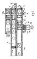
- Section 14 includes three chain conveyors 62, 63, 64.
- the end conveyors, 62 and 64 have a conveying speed while the speed of the central conveyor 63 is reduced.
- of the guide rails 67 are arranged on each side of section 14, at the outside of chain conveyors 62 to 64, to support and guide the plates 33.
- a mechanical arm detector (not shown) is mounted at the level of the central conveyor 63 to detect the presence plates 33.
- a limit switch 65 is mounted at the end of the conveyor 64 contiguous to the conveyor section 15 to detect the arrival of a plate 33 and trigger the operation of the roller conveyor 66 of the conveyor section 15.
- the central conveyor 63 includes two half conveyors 63a, 63b separated by a gap located in irradiation station 7.
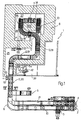
- This station includes a particle accelerator 70 provided with a scanning head, not shown, which is arranged above the path of the products to sterilize, directly above the gap separating the two half conveyors 63a, 63b, and an absorption well 71 arranged directly above a scanning head, below the level of the conveyors 63a, 63b, to absorb and dissipate excess energy from beta radiation.
- the conveyor 62 is constituted by a pair of chains 72
- the half conveyor 63a is constituted by a pair of chains 73
- the half conveyor 63b is constituted by a pair of chains 74
- the conveyor 64 is constituted by a pair of chains 75.
- the shaft 57 drives the pair of chains 75 via a chain transmission 76, a motor shaft 77 and a toothed wheel 78;
- the pair of chains 75 drives the 74 pair of chains via a train reducer 79 located below the conveyors;
- the pair of chains 74 drives the pair of chains 73 via a mechanism reference 80 arranged above the conveyors;
- the pair of chains 73 drives the pair of chains 72 via a train multiplier 81 located below the conveyors.
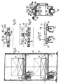
- the chains 72 to 75 include pairs of aligned drive members 84 (figure 12).
- Each drive member 84 is constituted by a pair of square-shaped elements 85 rigidly connected to each other the other at a first end 86 and pivotally connected to the chain at a second end 87 ( Figure 15).
- a roller 88 is pivotally mounted on the outside of each shaped element 85 square, at its bent part.
- the rollers 88 of a drive member 84 engage corresponding parallel straight guides 90 (see Figures 11 and 15) which has the effect of passing the drive member 84 from a retracted position where it is below the level of the rails guide 67 of the plates 33 (see FIG.
- the diagram also shows the limit switch 65 and the corresponding linkage 91 which used to operate the roller conveyor 66 of the conveyor sections 15 and 16.
- the connection between the conveyor sections 16 and 17 which does not are not at the same level is provided by a vertical carrier 92 (see Figure 10) which is intended to take a plate 33 arriving at the end of the roller conveyor 66 and transfer it to the roller conveyor 97 of the conveyor sections 17 and 18.
- the vertical conveyor 92 which is arranged in zone 26 of the box 6, includes a motor 93 for the vertical routing of the plates 33, a motor 94 for their horizontal routing as well as specific control means 95 for ensuring synchronization with roller conveyors 66 and 97.
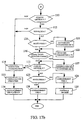
- the command and control unit 42 further checks whether the product code read on the box label 31 corresponds to that of previously loaded and processed products (block 102); in the negative (different products requiring a variation of treatment parameters, such as irradiation intensity produced by the accelerator 70 or the conveying speed of the conveyor 14), the control unit 42 actuates the blocking 58a, which causes the trays 33 already introduced to stop in the main loading station 2 (block 103) and requires the operator entering, at the auxiliary loading station 3, of a test plate 33a (block 104). To this end, provision can be made for station 3 adequate signaling means, not shown. The operator then introduces into the installation a test plate 33a containing operation control devices.
- the tray 33a test consists of two test boxes 31a, 31b ( Figure 5), the box 31a disposed first in the direction of travel being empty and the second box 31b containing means for measuring irradiation, such as a 96 calorimeter. Then, on command of operator or automatically, after the tray code has been read by reader 45 (block 105), after the operator has pressed a identification code button for the control and control (block 106) and after the tray code and code manually entered have been associated (block 107), the block 58a (block 108) are deactivated by advancing the plate manually introduced into auxiliary station 3 and the test platform 33a and trays 33 previously loaded at the station main load 2.
- the readers 51 and 52 When traveling along the conveyor means, the readers 51 and 52 (and possibly other non-readers represented) read the tray identification code to follow the routing of trays and products transported throughout the path outside the box (blocks 110, 111). Information provided by these readers, synchronization data of the motor 55 and, possibly, the data supplied by the mechanical limit switches 61, 65 with regard to inside the box 6 (block 112), are used by the command 42 to locate or identify precisely, at any moment, the exact position of each plate 33 inside the caisson. In the event of an anomaly or when the operation of the installation is interrupted, the boxes of products that have been totally treated, those that were partially treated and those whose the condition is not perfectly known can thus be identified.
- the command and control unit 42 can directly stop the treatment by stopping the accelerator 70 (block 114), by sending the corresponding error signals to the operator (115) and by unloading the plates 33 present on the conveying means 8 (116).
- the conveyor 62 of the conveyor section 14 is faster than conveyor 63 (whose two parts 63a and 63b move at the same speed).
- the conveyor 62 quickly moves the trays 33 away from the conveyor 60 brought by this conveyor and causes the trays to regroup 33 in the direction of travel so as to reduce the distance between two successive stages.
- the start of the guide rails 67 of the plates (not visible in the figures) and the position of the drives 84 of chains 72 are studied so that the drive bodies do not come into contact with the frame lower 36 of each tray 33 than when it arrived at the end of the conveying section 13, this in order to avoid rotation of the tray 33.
- Conveyors 62 and 63a are synchronized exactly from so that when a plate 33 reaches the conveyor 63a, a pair of drives 84 of chains 73 engages in bottom frame 36 of tray 33, after pivoting from position retracted shown in Figure 13 in the projecting position shown in Figure 14.
- Pivoting organs 84 has the effect of communicating a movement to them horizontal which is added to the displacement resulting from the training by chains 73; this pivoting therefore causes a slight increase in the speed of organs 84 compared to the speed of conveyor 63a.
- the plates 33 are very close together and travel at a speed constant, which ensures regular irradiation in the station irradiation 7.
- the conveyors 63a, 63b are behave like a single conveyor since their speeds are equal, and thanks to the gap between them they are not damaged by radiation.
- the unit command and control 42 determines when this tray 33a will reach the irradiation station 7, memorize the parameters of corresponding processing (block 121) and orders the modification irradiation parameters to adapt them to the new product to process (block 122). In this way, when the test plate 33a reaches the irradiation station 7, the accelerator 70 sets the parameters irradiation at the time of passage of the first box 31a (empty), and, during the passage of the second box 31b, the calorimeter 96 which it contains measures the dose received.
- test plate 33a is unloaded then at the auxiliary unloading station 5 and it is checked whether the received dose corresponds to the commanded value (blocks 123, 124, 125).
- a code reader can possibly be provided at the station. auxiliary unloading 5 to allow confirmation the correct routing of the test trays.
- the command and control unit 42 also continues to control the speed of the trays in the station 7 by a signal sent to the tacho dynamo 56 (block 126) and, if there is an abnormality in the engine speed 55 which can be compensated by an adjustment of the irradiated dose, it commands the modification of the operating parameters of the accelerator 70 (block 127).
- the trays 33 are transferred from the conveyor 63b to the conveyor 64, the speed of which has was chosen greater than that of the conveyors 63a, 63b so that treated trays 33 are rapidly conveyed to the end of the conveying section 14.
- the roller conveyor 66 actuates the roller conveyor 66 which drives the plate 33 out of section 14, without modifying it orientation.
- Conveyor 66 routes trays 33 to vertical conveyor 92 which takes them, one after the other, from the conveyor 66, brings them down to the level of conveyor 97, and transfers to the latter.
- the plates 33 loaded with irradiated boxes 31 are thus routed on the conveyor sections 17-20 below the conveyor sections for trays loaded with boxes 31 of products to be treated. In case they do not contain boxes 31a, 31b, the trays are conveyed by means of conveyors 47, 47b, 47c to the main unloading station 4 (block 128). There, the reader 38 reads the label 37 from the tray 33 and communicates to the control and processing unit 42 the arrival correct trays 33 at the exit of the installation.
- the installation described above has the following advantages. It is reliable and efficient, in particular thanks to the fact that, in the part central section 14, the spaces between the shelves are reduced to a few millimeters (which therefore practically reduces the idle time of the accelerator). Its performance high is also due to the fact that it allows to modify the parameters of irradiation required by different products without having to stop installation.
- the constant conveying speed guarantees uniformity of irradiation received by products and can handle delicate products, such as PVC blood lines, for which the gap is reduced between the maximum and minimum allowable doses to ensure sterilization and avoid deterioration of the products.
- Control of the entire conveying, including inside the box helps to ensure reliability of the installation and compensates for low speed irregularities, as described above.
- the unit of command and control is able to detect any anomaly likely to affect the effectiveness of sterilization, to interrupt the treatment, and distinguish the boxes that have been treated from those which were not or insufficiently.
- the identification of all the trays and boxes they support is ensured, even when the accelerator is off, without interrupting conveying the trays. Furthermore, the inaccessibility of all of the conveying means thanks to the trellis cage 43 and in box 6 guarantees that it is impossible to modify the boxes / trays associations established at the entrance to the installation.
Landscapes
- Health & Medical Sciences (AREA)
- Epidemiology (AREA)
- Life Sciences & Earth Sciences (AREA)
- Animal Behavior & Ethology (AREA)
- General Health & Medical Sciences (AREA)
- Public Health (AREA)
- Veterinary Medicine (AREA)
- Apparatus For Disinfection Or Sterilisation (AREA)
- Warehouses Or Storage Devices (AREA)
- Agricultural Chemicals And Associated Chemicals (AREA)
Description
- au moins une station de chargement de produits,
- au moins une station de déchargement de produits,
- une station d'irradiation située à l'intérieur d'un caisson ayant des parois aptes à arrêter les rayonnements stérilisants,
- des moyens de convoyage pour acheminer les produits à stériliser de la station de chargement à la station d'irradiation et les produits stérilisés de la station d'irradiation à la station de déchargement, les moyens de convoyage comprenant des moyens de regroupement pour regrouper les produits à stériliser à proximité de la station d'irradiation, les moyens de regroupement comprenant un premier convoyeur et un deuxième convoyeur, le deuxième convoyeur étant situé immédiatement en aval du premier convoyeur par rapport à la direction de convoyage des produits et ayant une vitesse de convoyage inférieure à la vitesse de convoyage du premier convoyeur.
- des sections de convoyage superposées, les sections de convoyage situées à un premier niveau acheminant les produits à stériliser de la station de chargement à la station d'irradiation et les sections de convoyage situées à un second niveau acheminant les produits stérilisés de la station d'irradiation à la station de déchargement.
- un transporteur vertical pour transférer les produits d'un niveau de convoyage à l'autre niveau de convoyage.
- une première section 10 disposée dans le prolongement de la station de chargement principale 2,
- une deuxième section 11 perpendiculaire à la première section 10,
- une troisième section 12 perpendiculaire à la deuxième section 11 et s'étendant dans une direction opposée à celle de la première section 10,
- une quatrième section 13 perpendiculaire à la troisième section 12 et s'étendant dans la même direction que la deuxième section 11,
- une cinquième section 14, traversant la station d'irradiation 7, perpendiculaire à la quatrième section 13 et s'étendant dans une direction opposée à celle de la troisième section 12,
- une sixième section 15 perpendiculaire à la cinquième section 14 et s'étendant dans une direction opposée à celle de la quatrième section 13,
- une septième section 16 de forme courbe ayant sa concavité tournée vers la station d'irradiation 7,
- une huitième section 17 de forme courbe ayant sa concavité tournée à l'opposé de la station d'irradiation 7, cette huitième section 17 étant dans un plan situé au-dessous d'un plan parallèle contenant les sept sections précédentes,
- une neuvième section 18, une dixième section 19 et une onzième section 20, s'étendant respectivement au dessous de la quatrième section 13, de la troisième section 12 et de la deuxième section 11, et
- une douzième section 21 parallèle à la première section 10 et prolongée par la station de déchargement principale 4.
- une première zone 25 d'entrée et de sortie, contenant une partie des sections 11, 20, les sections 12, 19 et une partie des sections 13, 18,
- une seconde zone 26, intermédiaire, contenant une partie des sections 13, 18 et les sections 15 à 17, et
- une troisième zone 27 contenant la section 14 et la station d'irradiation 7.
Claims (14)
- Installation de stérilisation (1) de produits médicaux (31) par irradiation, comprenant:au moins une station de chargement (2) de produits,au moins une station de déchargement (4) de produits,une station d'irradiation (7) située à l'intérieur d'un caisson (6) ayant des parois aptes à arrêter les rayonnements stérilisants,des moyens de convoyage (10-21) pour acheminer les produits (31) à stériliser de la station de chargement (2) à la station d'irradiation (7) et les produits (31) stérilisés de la station d'irradiation (7) à la station de déchargement (4), les moyens de convoyage comprenant des moyens de regroupement (62, 63) pour regrouper les produits (31) à stériliser à proximité de la station d'irradiation (7), les moyens de regroupement comprenant un premier convoyeur (62) et un deuxième convoyeur (63), le deuxième convoyeur (63) étant situé immédiatement en aval du premier convoyeur (62) par rapport à la direction de convoyage des produits (31) et ayant une vitesse de convoyage inférieure à la vitesse de convoyage du premier convoyeur (62).
- Installation selon la revendication 1 , caractérisée en ce que le premier et le deuxième convoyeurs (62, 63) comprennent des organes d'entraínement (84) rétractables pour accrocher les produits (31) et assujettir rigoureusement leur déplacement à celui du convoyeur (62, 63) correspondant.
- Installation selon une des revendications 1 et 2, caractérisée en ce que le deuxième convoyeur (63) comprend deux demi convoyeurs (63a, 63b) séparés par un interstice disposé dans une zone vers laquelle la station d'irradiation (7) émet les rayonnements stérilisants.
- Installation selon une des revendications 2 à 3, caractérisée en ce qu'elle comprend un troisième convoyeur (64) situé immédiatement en aval du deuxième convoyeur (63) par rapport à la direction de convoyage des produits (31), le troisième convoyeur (64) ayant une vitesse de convoyage supérieure à la vitesse de convoyage du deuxième convoyeur (63).
- Installation selon une des revendications 3 et 4, caractérisée en ce que au moins le premier et le deuxième convoyeurs (62, 63) sont des convoyeurs à chaínes comprenant chacun une paire de chaínes (72, 73, 74) et en ce que les organes d'entraínement (84) comprennent chacun un doigt et sont montés pivotants sur les chaínes pour pouvoir pivoter entre une position rétractée où le doigt ne peut pas accrocher de produit (31) et une position saillante où le doigt peut accrocher un produit (31).
- Installation selon l'une des revendications 1 à 5, caractérisée en ce que les moyens de convoyage (10-21) comprennent des sections de convoyage (11-13 et 18-20) superposées, les sections de convoyage (11-13) situées à un premier niveau acheminant les produits (31) à stériliser de la station de chargement (2) à la station d'irradiation (7) et les sections de convoyage (18-20) situées à un second niveau acheminant les produits (31) stérilisés de la station d'irradiation (7) à la station de déchargement (4).
- Installation selon la revendication 6, caractérisée en ce les moyens de convoyage (10-21) comprennent un transporteur vertical (92) pour transférer les produits (31) d'un niveau de convoyage à l'autre niveau de convoyage.
- Installation selon l'une des revendications 1 à 7, caractérisée en ce qu'elle comprend des moyens de détection (38, 40, 41, 44, 45, 51, 52, 61, 65) de produits (31), disposés le long des moyens de convoyage (10-21), et des moyens de commande et de contrôle (42) reliés aux moyens de détection pour suivre le cheminement des produits (31) sur les moyens de convoyage (10-21).
- Installation selon la revendication 8, caractérisée en ce qu'elle comprend une pluralité de plateaux (33) destinés à supporter les produits (31) sur les moyens de convoyage (10-21), chaque plateau (33) étant muni d'un code d'identification (37), les moyens de détection de produits (31) comprenant des moyens de lecture de code (38, 40, 41, 44, 45, 51, 52) aptes à lire le code (37) apposé sur chaque plateau (33).
- Installation selon la revendication 9, caractérisée en ce que les moyens de détection de produits (31) comprennent des moyens de lecture de code (38, 40, 41, 44, 45, 51, 52) aptes à lire un code d'identification (32) apposé sur chacun des produits (31) disposé sur chaque plateau (33) et en ce que l'unité de commande et de contrôle (42) est prévue pour associer et mettre en mémoire le code d'identification (32) de chaque produit (31) et le code d'identification (37) du plateau qui supporte ce produit (31).
- Installation selon une des revendication 9 et 10 à 11, caractérisée en ce que les moyens de détection de produits (31) comprennent des moyens de détection de fin de course mécaniques (61, 65) disposés à l'intérieur du caisson (6) pour détecter la position des plateaux (33) à l'intérieur du caisson (6) et transmettre un signal correspondant à l'unité de commande et de contrôle (42).
- Installation selon une des revendication 8 à 11, caractérisée en ce que les moyens de détection de produits (31) comprennent des moyens de lecture de code (40, 41, 44) disposés à proximité de la station de chargement (2), et en ce que les moyens de commande et de contrôle (42) sont prévus pour comparer chaque produit (31) introduit dans la station de chargement (5) au produit introduit précédemment et pour commander le déclenchement de moyens d'avertissement lorsque ces produits ne sont pas de même type.
- Installation selon une des revendication 8 à 12, caractérisée en ce qu'elle comporte des moyens de mesure (56) de la vitesse du deuxième convoyeur (63) reliés aux moyens de commande et de contrôle (42), et en ce que les moyens de commande et de contrôle (42) sont prévus pour ajuster l'irradiation émise par la station d'irradiation en fonction des variations de la vitesse du convoyeur (63) de façon que les produits (31) reçoivent une dose d'irradiation prédéterminée .
- Installation selon une des revendications 1 à 13, caractérisée en ce qu'elle comprend une cage en treillis (43) entourant les moyens de convoyage (10-21) à l'extérieur du caisson (6).
Priority Applications (1)
| Application Number | Priority Date | Filing Date | Title |
|---|---|---|---|
| EP03075810A EP1323435B1 (fr) | 1996-12-17 | 1997-12-16 | Procédé de stérilisation de produits médicaux par irradiation et installation |
Applications Claiming Priority (3)
| Application Number | Priority Date | Filing Date | Title |
|---|---|---|---|
| ITTO961037 | 1996-12-17 | ||
| IT96TO001037A IT1289760B1 (it) | 1996-12-17 | 1996-12-17 | Impianto di sterilizzazione di prodotti medicali tramite irraggiamento di raggi beta. |
| PCT/IB1997/001570 WO1998026805A1 (fr) | 1996-12-17 | 1997-12-16 | Installation de sterilisation de produits medicaux par irradiation par rayons beta |
Related Child Applications (1)
| Application Number | Title | Priority Date | Filing Date |
|---|---|---|---|
| EP03075810A Division EP1323435B1 (fr) | 1996-12-17 | 1997-12-16 | Procédé de stérilisation de produits médicaux par irradiation et installation |
Publications (2)
| Publication Number | Publication Date |
|---|---|
| EP0888133A1 EP0888133A1 (fr) | 1999-01-07 |
| EP0888133B1 true EP0888133B1 (fr) | 2003-06-18 |
Family
ID=11415118
Family Applications (2)
| Application Number | Title | Priority Date | Filing Date |
|---|---|---|---|
| EP03075810A Expired - Lifetime EP1323435B1 (fr) | 1996-12-17 | 1997-12-16 | Procédé de stérilisation de produits médicaux par irradiation et installation |
| EP97947180A Expired - Lifetime EP0888133B1 (fr) | 1996-12-17 | 1997-12-16 | Installation de sterilisation de produits medicaux par irradiation |
Family Applications Before (1)
| Application Number | Title | Priority Date | Filing Date |
|---|---|---|---|
| EP03075810A Expired - Lifetime EP1323435B1 (fr) | 1996-12-17 | 1997-12-16 | Procédé de stérilisation de produits médicaux par irradiation et installation |
Country Status (8)
| Country | Link |
|---|---|
| US (1) | US6177677B1 (fr) |
| EP (2) | EP1323435B1 (fr) |
| JP (1) | JP4162718B2 (fr) |
| AT (2) | ATE243047T1 (fr) |
| DE (2) | DE69722921T2 (fr) |
| ES (2) | ES2199377T3 (fr) |
| IT (1) | IT1289760B1 (fr) |
| WO (1) | WO1998026805A1 (fr) |
Families Citing this family (26)
| Publication number | Priority date | Publication date | Assignee | Title |
|---|---|---|---|---|
| US6285030B1 (en) * | 1997-05-09 | 2001-09-04 | The Titan Corporation | Article irradiation system in which article transporting conveyor is closely encompassed by shielding material |
| US6492645B1 (en) * | 1999-06-30 | 2002-12-10 | Surebeam Corporation | System for, and method of, irradiating articles to sterilize the articles |
| AU2001278132A1 (en) * | 2000-08-02 | 2002-02-13 | Sicel Technologies, Inc. | Evaluation of irradiated foods and other items with telemetric dosimeters and associated methods |
| US6628750B1 (en) * | 2000-11-09 | 2003-09-30 | Steris Inc. | System for electron and x-ray irradiation of product |
| US6529577B1 (en) * | 2000-12-29 | 2003-03-04 | Surebeam Corporation | System for, and method of, irradiating article with x-ray beam |
| US6690020B2 (en) * | 2001-10-04 | 2004-02-10 | Surebeam Corporation | Compact self-shielded irradiation system and method |
| GB2381751A (en) * | 2001-11-08 | 2003-05-14 | Aaron Goodall | Safety surgical sterilisation tool and system |
| US7557353B2 (en) * | 2001-11-30 | 2009-07-07 | Sicel Technologies, Inc. | Single-use external dosimeters for use in radiation therapies |
| US6686596B2 (en) * | 2002-02-21 | 2004-02-03 | Scandinova Ab | System and method of irradiating products being conveyed past an electron beam delivery device |
| EP2433871A3 (fr) * | 2002-06-19 | 2012-07-11 | Medical Instill Technologies, Inc. | Machine de remplissage stérile comprenant une station de remplissage par aiguille à l'interieur d'une chambre à faisceau d'electrons |
| US6815691B1 (en) * | 2003-05-06 | 2004-11-09 | The Titan Corporation | Compact self-shielded irradiation system and method |
| US8758679B2 (en) | 2006-03-31 | 2014-06-24 | The Invention Science Fund I, Llc | Surveying sterilizer methods and systems |
| US11185604B2 (en) * | 2006-03-31 | 2021-11-30 | Deep Science Llc | Methods and systems for monitoring sterilization status |
| US20070231192A1 (en) * | 2006-03-31 | 2007-10-04 | Searete Llc, A Limited Liability Corporation Of The State Of Delaware | Sterilization methods and systems |
| US8277724B2 (en) * | 2006-03-31 | 2012-10-02 | The Invention Science Fund I, Llc | Sterilization methods and systems |
| US8932535B2 (en) * | 2006-03-31 | 2015-01-13 | The Invention Science Fund I, Llc | Surveying sterilizer methods and systems |
| US7638090B2 (en) * | 2006-03-31 | 2009-12-29 | Searete Llc | Surveying sterilizer methods and systems |
| US8114342B2 (en) * | 2006-03-31 | 2012-02-14 | The Invention Science Fund I, Llc | Methods and systems for monitoring sterilization status |
| US20070254015A1 (en) * | 2006-04-28 | 2007-11-01 | Searete Llc, A Limited Liability Corporation Of The State Of Delaware | Sanitizing surfaces |
| CN101210892B (zh) * | 2006-12-28 | 2010-08-25 | 同方威视技术股份有限公司 | 一种用于航空集装箱ct检测的复合回转传送工作台 |
| US7669883B2 (en) * | 2007-03-29 | 2010-03-02 | Newfrey Llc | Air bag bracket/fastener |
| US10613036B2 (en) * | 2015-10-09 | 2020-04-07 | United Sortation Solutions, Llc | Conveying and cleaning system and methods for cleaning and stacking trays and/or layer pads |
| PL3657220T3 (pl) * | 2018-11-23 | 2025-01-07 | Tetra Laval Holdings & Finance S.A. | Narzędzie pomiarowe do źródła napromieniowania i sposób pomiaru promieniowania |
| EP3983022B1 (fr) * | 2019-06-14 | 2023-07-26 | Framatome GmbH | Installation permettant de stériliser des unités de stérilisation et procédé permettant de faire fonctionner une telle installation |
| CN111169933B (zh) * | 2020-01-22 | 2024-11-08 | 北京鸿仪四方辐射技术股份有限公司 | 一种控制辐照箱进行辐照运行的控制系统 |
| CN117205350B (zh) * | 2023-09-27 | 2025-10-21 | 完美(广东)日用品有限公司 | 一种智能化洁净车间传递物料的消毒方法 |
Family Cites Families (10)
| Publication number | Priority date | Publication date | Assignee | Title |
|---|---|---|---|---|
| GB764337A (en) * | 1954-02-01 | 1956-12-28 | Vickers Electrical Co Ltd | Improvements relating to the treatment of materials by electronic bombardment |
| GB1002601A (en) * | 1961-11-10 | 1965-08-25 | Nuclear Chemical Plant Ltd | Improvements in or relating to conveyor systems |
| US3264473A (en) * | 1963-06-26 | 1966-08-02 | Marquardt Corp | Radiation sterilization device with uniformly distributed beta emitters |
| CH413136A (de) * | 1964-04-14 | 1966-05-15 | Sulzer Ag | Bestrahlungsanlage |
| CH582404A5 (fr) * | 1974-09-02 | 1976-11-30 | Sulzer Ag | |
| CH611847A5 (en) * | 1974-10-16 | 1979-06-29 | Aluminiumwerke Ag Rorschach | Process and apparatus for the sterilisation, filling and closing of packaging containers |
| US4020354A (en) * | 1975-05-22 | 1977-04-26 | The Goodyear Tire & Rubber Company | Treatment of tire making components |
| US5400382A (en) * | 1992-04-19 | 1995-03-21 | Alpha Omega Technologies, Inc. | Automated irradiator for the processing of products and a method of operation |
| US5396074A (en) * | 1993-03-19 | 1995-03-07 | The Titan Corporation | Irradiation system utilizing conveyor-transported article carriers |
| US5667753A (en) * | 1994-04-28 | 1997-09-16 | Advanced Sterilization Products | Vapor sterilization using inorganic hydrogen peroxide complexes |
-
1996
- 1996-12-17 IT IT96TO001037A patent/IT1289760B1/it active IP Right Grant
-
1997
- 1997-12-16 US US09/125,229 patent/US6177677B1/en not_active Expired - Fee Related
- 1997-12-16 EP EP03075810A patent/EP1323435B1/fr not_active Expired - Lifetime
- 1997-12-16 AT AT97947180T patent/ATE243047T1/de not_active IP Right Cessation
- 1997-12-16 ES ES97947180T patent/ES2199377T3/es not_active Expired - Lifetime
- 1997-12-16 DE DE69722921T patent/DE69722921T2/de not_active Expired - Lifetime
- 1997-12-16 ES ES03075810T patent/ES2231755T3/es not_active Expired - Lifetime
- 1997-12-16 JP JP52750098A patent/JP4162718B2/ja not_active Expired - Fee Related
- 1997-12-16 EP EP97947180A patent/EP0888133B1/fr not_active Expired - Lifetime
- 1997-12-16 DE DE69731242T patent/DE69731242T2/de not_active Expired - Lifetime
- 1997-12-16 WO PCT/IB1997/001570 patent/WO1998026805A1/fr not_active Ceased
- 1997-12-16 AT AT03075810T patent/ATE279217T1/de not_active IP Right Cessation
Also Published As
| Publication number | Publication date |
|---|---|
| EP0888133A1 (fr) | 1999-01-07 |
| DE69731242T2 (de) | 2005-10-20 |
| EP1323435B1 (fr) | 2004-10-13 |
| ITTO961037A1 (it) | 1998-06-17 |
| ATE279217T1 (de) | 2004-10-15 |
| EP1323435A1 (fr) | 2003-07-02 |
| JP2000507490A (ja) | 2000-06-20 |
| DE69722921D1 (de) | 2003-07-24 |
| US6177677B1 (en) | 2001-01-23 |
| ES2199377T3 (es) | 2004-02-16 |
| JP4162718B2 (ja) | 2008-10-08 |
| IT1289760B1 (it) | 1998-10-16 |
| ES2231755T3 (es) | 2005-05-16 |
| ATE243047T1 (de) | 2003-07-15 |
| DE69731242D1 (de) | 2004-11-18 |
| DE69722921T2 (de) | 2004-05-19 |
| WO1998026805A1 (fr) | 1998-06-25 |
Similar Documents
| Publication | Publication Date | Title |
|---|---|---|
| EP1323435B1 (fr) | Procédé de stérilisation de produits médicaux par irradiation et installation | |
| CN107531428B (zh) | 具有基于物品特性的转移率的滑动分选器弹出式分流输送机 | |
| US5400382A (en) | Automated irradiator for the processing of products and a method of operation | |
| US20240199401A1 (en) | Container treatment system and container treatment method for treating containers | |
| FR2728249A1 (fr) | Procede et appareil de transport automatique de pieces | |
| JP2019516994A (ja) | オブジェクト検知並びにハンドリングシステム及び関連する方法 | |
| JP3566215B2 (ja) | 農作物の搬送処理装置 | |
| JP6484666B2 (ja) | 制御装置 | |
| KR100194531B1 (ko) | 포장재의 절개 및 제거장치 | |
| KR101793588B1 (ko) | 포장용기 반전장치가 포함된 자동 포장시스템 | |
| FR2696722A1 (fr) | Robot tunnel destiné au stockage et à la préparation automatisée de commande pour des objets de formes et de tailles diverses, et notamment de médicaments conditionnés en boîtes. | |
| JP2003227804A (ja) | X線検査装置 | |
| EP0675458A1 (fr) | Procédé automatique d'étiquetage et de contrôle de poches de sang en retour d'analyse et machine en comportant application | |
| US4044891A (en) | Can testing conveyor | |
| US4718536A (en) | Stack storage elevator for sliced, stacked comestible products | |
| JP2008283909A (ja) | 青果物表皮の殺菌装置 | |
| EP0646421B1 (fr) | Installation perfectionnée pour identifier et peser en continu un colis, dont l'étiquette présente un ensemble code à barres | |
| FR3055316A3 (fr) | Installation de traitement de contenants avec reconversion entre des etats planifies | |
| JP2017072411A (ja) | 包装体の検査装置及び包装体の検査方法 | |
| EP0842877A1 (fr) | Machine de traitement en ligne de récipients et ligne de transfert pneumatique de récipients équipée de cette machine | |
| JP2001187625A (ja) | 光照射用コンベア | |
| EP4323127B1 (fr) | Installation de traitement de produits horticoles | |
| JP2004325281A (ja) | 農産物非破壊品質判定装置 | |
| JP7199996B2 (ja) | X線検査装置 | |
| JP2002211508A (ja) | 卵包装装置及び卵自動選別システム |
Legal Events
| Date | Code | Title | Description |
|---|---|---|---|
| PUAI | Public reference made under article 153(3) epc to a published international application that has entered the european phase |
Free format text: ORIGINAL CODE: 0009012 |
|
| 17P | Request for examination filed |
Effective date: 19980730 |
|
| AK | Designated contracting states |
Kind code of ref document: A1 Designated state(s): AT BE CH DE ES FR GB GR IE IT LI NL PT SE |
|
| RAP1 | Party data changed (applicant data changed or rights of an application transferred) |
Owner name: GAMBRO HOSPAL (SCHWEIZ) AG |
|
| 17Q | First examination report despatched |
Effective date: 20020812 |
|
| GRAH | Despatch of communication of intention to grant a patent |
Free format text: ORIGINAL CODE: EPIDOS IGRA |
|
| RTI1 | Title (correction) |
Free format text: SYSTEM FOR STERILIZING MEDICINAL PRODUCTS BY RADIATION PROCESSING |
|
| GRAH | Despatch of communication of intention to grant a patent |
Free format text: ORIGINAL CODE: EPIDOS IGRA |
|
| GRAA | (expected) grant |
Free format text: ORIGINAL CODE: 0009210 |
|
| AK | Designated contracting states |
Designated state(s): AT BE CH DE ES FR GB GR IE IT LI NL PT SE |
|
| PG25 | Lapsed in a contracting state [announced via postgrant information from national office to epo] |
Ref country code: NL Free format text: LAPSE BECAUSE OF FAILURE TO SUBMIT A TRANSLATION OF THE DESCRIPTION OR TO PAY THE FEE WITHIN THE PRESCRIBED TIME-LIMIT Effective date: 20030618 Ref country code: IE Free format text: LAPSE BECAUSE OF FAILURE TO SUBMIT A TRANSLATION OF THE DESCRIPTION OR TO PAY THE FEE WITHIN THE PRESCRIBED TIME-LIMIT Effective date: 20030618 Ref country code: AT Free format text: LAPSE BECAUSE OF FAILURE TO SUBMIT A TRANSLATION OF THE DESCRIPTION OR TO PAY THE FEE WITHIN THE PRESCRIBED TIME-LIMIT Effective date: 20030618 |
|
| REG | Reference to a national code |
Ref country code: GB Ref legal event code: FG4D Free format text: NOT ENGLISH |
|
| REG | Reference to a national code |
Ref country code: CH Ref legal event code: EP |
|
| REG | Reference to a national code |
Ref country code: IE Ref legal event code: FG4D Free format text: FRENCH |
|
| REF | Corresponds to: |
Ref document number: 69722921 Country of ref document: DE Date of ref document: 20030724 Kind code of ref document: P |
|
| PG25 | Lapsed in a contracting state [announced via postgrant information from national office to epo] |
Ref country code: PT Free format text: LAPSE BECAUSE OF FAILURE TO SUBMIT A TRANSLATION OF THE DESCRIPTION OR TO PAY THE FEE WITHIN THE PRESCRIBED TIME-LIMIT Effective date: 20030918 Ref country code: GR Free format text: LAPSE BECAUSE OF FAILURE TO SUBMIT A TRANSLATION OF THE DESCRIPTION OR TO PAY THE FEE WITHIN THE PRESCRIBED TIME-LIMIT Effective date: 20030918 |
|
| REG | Reference to a national code |
Ref country code: SE Ref legal event code: TRGR |
|
| GBT | Gb: translation of ep patent filed (gb section 77(6)(a)/1977) |
Effective date: 20031008 |
|
| NLV1 | Nl: lapsed or annulled due to failure to fulfill the requirements of art. 29p and 29m of the patents act | ||
| PG25 | Lapsed in a contracting state [announced via postgrant information from national office to epo] |
Ref country code: LI Free format text: LAPSE BECAUSE OF NON-PAYMENT OF DUE FEES Effective date: 20031231 Ref country code: CH Free format text: LAPSE BECAUSE OF NON-PAYMENT OF DUE FEES Effective date: 20031231 Ref country code: BE Free format text: LAPSE BECAUSE OF NON-PAYMENT OF DUE FEES Effective date: 20031231 |
|
| REG | Reference to a national code |
Ref country code: IE Ref legal event code: FD4D |
|
| REG | Reference to a national code |
Ref country code: ES Ref legal event code: FG2A Ref document number: 2199377 Country of ref document: ES Kind code of ref document: T3 |
|
| PLBE | No opposition filed within time limit |
Free format text: ORIGINAL CODE: 0009261 |
|
| STAA | Information on the status of an ep patent application or granted ep patent |
Free format text: STATUS: NO OPPOSITION FILED WITHIN TIME LIMIT |
|
| 26N | No opposition filed |
Effective date: 20040319 |
|
| BERE | Be: lapsed |
Owner name: *GAMBRO HOSPAL (SCHWEIZ) A.G. Effective date: 20031231 |
|
| REG | Reference to a national code |
Ref country code: CH Ref legal event code: PL |
|
| REG | Reference to a national code |
Ref country code: GB Ref legal event code: 732E |
|
| PGFP | Annual fee paid to national office [announced via postgrant information from national office to epo] |
Ref country code: GB Payment date: 20101123 Year of fee payment: 14 |
|
| PGFP | Annual fee paid to national office [announced via postgrant information from national office to epo] |
Ref country code: SE Payment date: 20111207 Year of fee payment: 15 Ref country code: ES Payment date: 20111220 Year of fee payment: 15 Ref country code: FR Payment date: 20111205 Year of fee payment: 15 |
|
| PGFP | Annual fee paid to national office [announced via postgrant information from national office to epo] |
Ref country code: DE Payment date: 20111230 Year of fee payment: 15 |
|
| PGFP | Annual fee paid to national office [announced via postgrant information from national office to epo] |
Ref country code: IT Payment date: 20111228 Year of fee payment: 15 |
|
| PG25 | Lapsed in a contracting state [announced via postgrant information from national office to epo] |
Ref country code: SE Free format text: LAPSE BECAUSE OF NON-PAYMENT OF DUE FEES Effective date: 20121217 |
|
| GBPC | Gb: european patent ceased through non-payment of renewal fee |
Effective date: 20121216 |
|
| REG | Reference to a national code |
Ref country code: FR Ref legal event code: ST Effective date: 20130830 |
|
| PG25 | Lapsed in a contracting state [announced via postgrant information from national office to epo] |
Ref country code: DE Free format text: LAPSE BECAUSE OF NON-PAYMENT OF DUE FEES Effective date: 20130702 |
|
| REG | Reference to a national code |
Ref country code: DE Ref legal event code: R119 Ref document number: 69722921 Country of ref document: DE Effective date: 20130702 |
|
| PG25 | Lapsed in a contracting state [announced via postgrant information from national office to epo] |
Ref country code: GB Free format text: LAPSE BECAUSE OF NON-PAYMENT OF DUE FEES Effective date: 20121216 Ref country code: FR Free format text: LAPSE BECAUSE OF NON-PAYMENT OF DUE FEES Effective date: 20130102 |
|
| PG25 | Lapsed in a contracting state [announced via postgrant information from national office to epo] |
Ref country code: IT Free format text: LAPSE BECAUSE OF NON-PAYMENT OF DUE FEES Effective date: 20121216 |
|
| REG | Reference to a national code |
Ref country code: ES Ref legal event code: FD2A Effective date: 20140307 |
|
| PG25 | Lapsed in a contracting state [announced via postgrant information from national office to epo] |
Ref country code: ES Free format text: LAPSE BECAUSE OF NON-PAYMENT OF DUE FEES Effective date: 20121217 |