EP0887625B1 - Optische Positionsmesseinrichtung - Google Patents
Optische Positionsmesseinrichtung Download PDFInfo
- Publication number
- EP0887625B1 EP0887625B1 EP98110401A EP98110401A EP0887625B1 EP 0887625 B1 EP0887625 B1 EP 0887625B1 EP 98110401 A EP98110401 A EP 98110401A EP 98110401 A EP98110401 A EP 98110401A EP 0887625 B1 EP0887625 B1 EP 0887625B1
- Authority
- EP
- European Patent Office
- Prior art keywords
- reference pulse
- measuring device
- position measuring
- scale
- optical position
- Prior art date
- Legal status (The legal status is an assumption and is not a legal conclusion. Google has not performed a legal analysis and makes no representation as to the accuracy of the status listed.)
- Expired - Lifetime
Links
- 230000003287 optical effect Effects 0.000 title claims abstract description 76
- 230000001788 irregular Effects 0.000 claims abstract description 12
- 230000005693 optoelectronics Effects 0.000 claims abstract description 8
- 238000009826 distribution Methods 0.000 claims description 46
- 230000000295 complement effect Effects 0.000 claims description 18
- 230000000149 penetrating effect Effects 0.000 claims 1
- 230000005540 biological transmission Effects 0.000 abstract description 27
- 238000005070 sampling Methods 0.000 abstract description 7
- 238000005457 optimization Methods 0.000 description 14
- 238000000034 method Methods 0.000 description 11
- 238000001514 detection method Methods 0.000 description 5
- 230000036540 impulse transmission Effects 0.000 description 5
- 230000005855 radiation Effects 0.000 description 4
- 238000005286 illumination Methods 0.000 description 3
- 238000010276 construction Methods 0.000 description 2
- 238000011156 evaluation Methods 0.000 description 2
- 239000011521 glass Substances 0.000 description 2
- 229910000831 Steel Inorganic materials 0.000 description 1
- 230000015572 biosynthetic process Effects 0.000 description 1
- 239000004020 conductor Substances 0.000 description 1
- 230000001419 dependent effect Effects 0.000 description 1
- 230000000694 effects Effects 0.000 description 1
- 230000003993 interaction Effects 0.000 description 1
- 230000000737 periodic effect Effects 0.000 description 1
- 238000004513 sizing Methods 0.000 description 1
- 230000006641 stabilisation Effects 0.000 description 1
- 238000011105 stabilization Methods 0.000 description 1
- 239000010959 steel Substances 0.000 description 1
- 230000001629 suppression Effects 0.000 description 1
Images

Classifications
-
- G—PHYSICS
- G01—MEASURING; TESTING
- G01D—MEASURING NOT SPECIALLY ADAPTED FOR A SPECIFIC VARIABLE; ARRANGEMENTS FOR MEASURING TWO OR MORE VARIABLES NOT COVERED IN A SINGLE OTHER SUBCLASS; TARIFF METERING APPARATUS; MEASURING OR TESTING NOT OTHERWISE PROVIDED FOR
- G01D5/00—Mechanical means for transferring the output of a sensing member; Means for converting the output of a sensing member to another variable where the form or nature of the sensing member does not constrain the means for converting; Transducers not specially adapted for a specific variable
- G01D5/26—Mechanical means for transferring the output of a sensing member; Means for converting the output of a sensing member to another variable where the form or nature of the sensing member does not constrain the means for converting; Transducers not specially adapted for a specific variable characterised by optical transfer means, i.e. using infrared, visible, or ultraviolet light
- G01D5/32—Mechanical means for transferring the output of a sensing member; Means for converting the output of a sensing member to another variable where the form or nature of the sensing member does not constrain the means for converting; Transducers not specially adapted for a specific variable characterised by optical transfer means, i.e. using infrared, visible, or ultraviolet light with attenuation or whole or partial obturation of beams of light
- G01D5/34—Mechanical means for transferring the output of a sensing member; Means for converting the output of a sensing member to another variable where the form or nature of the sensing member does not constrain the means for converting; Transducers not specially adapted for a specific variable characterised by optical transfer means, i.e. using infrared, visible, or ultraviolet light with attenuation or whole or partial obturation of beams of light the beams of light being detected by photocells
- G01D5/36—Forming the light into pulses
- G01D5/366—Particular pulse shapes
Definitions
- the present invention relates to an optical position measuring device, in in addition to the generation of incremental position data also the generation at least one reference pulse signal at a defined relative position two mutually movable objects is possible.
- Known optical, incremental position measuring devices include besides one or more incremental graduations on scale and scan side usually also one or more fields with reference marks or Reference mark structures, via the corresponding reference pulse signals can be generated.
- the reference pulse signals are used here for unique Identification of defined relative positions of the two mutually movable Elements whose relative movement by means of the optical position measuring device to be detected. For example, it is with each other movable elements around the workpiece and the tool a numerically controlled machine tool.
- the reference mark structure is on scale and scan side from a number of alternately arranged areas with optical different properties. Depending on whether it is a position measuring device is operated in transmitted light or in reflected light the areas are either optically permeable and non-transmissive or formed reflective and non-reflective. Both on pages the scale as well as on the part of the scanning unit are usually the identical periodic structures arranged in a reference mark field. The illumination is done with a collimated beam. Each permeable area on scale page is at the appropriate Relative position associated with exactly one permeable area on the scan side. In this context, for example, to DE 18 14 785 of the Applicant directed.
- the object of the present invention is therefore, for an optical position measuring device, which does not require collimation optics, a way to create a high-resolution reference pulse signal to one or more to generate defined positions.
- optical position measuring device arise from the measures in the dependent Claims.
- a reference pulse transmission structure, a reference pulse scanning structure and a reference pulse scale structure coordinated with each other via a suitable optimization procedure.
- optical position measuring device As a further advantage of the optical position measuring device according to the invention it should be noted that in certain arrangements of structures for Generation of reference pulse signals relative to an incremental graduation high moire insensitivity results. Especially with a possible slight relative rotation of scale graduation and scanning unit around an axis perpendicular to the measuring direction changes the shape and position of the reference pulse signal generated according to the invention is not practical.
- the proposed measures are also particularly advantageous. in addition to a first reference pulse signal in the manner according to the invention and a complementary thereto second reference pulse signal produce. In this way, the detection reliability in the detection or Increase evaluation of reference pulse signals.
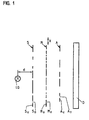
- the optical position measuring device according to the invention comprises for generating at least one reference pulse signal a light source LQ, for example formed as an LED.
- a light source LQ for example formed as an LED.
- the light source LQ according to the invention follows a reference pulse transmission structure S which has an irregular or aperiodic first distribution of regions S U , S D with different optical properties.
- the regions S D , S U of the reference pulse transmission structure S are alternately optically permeable and non-transmissive.
- no additional optics are arranged between the light source LQ and the reference pulse transmission structure S, which serves for collimation of the radiation beam delivered by the light source.
- a divergent beam path is provided between the light source and the downstream reference pulse transmission structure, ie. a divergent lighting. Such a very compact construction of the same is possible.
- the light source LQ is in a defined Distance d away from the reference pulse transmission structure S arranged.
- the Distance d between the light source LQ and the reference pulse transmission structure S are also chosen to be much smaller, up to the special case d ⁇ 0. In this way, the divergence of the light source can be LQ vary.
- the ones to be selected change Structures for generating the reference pulse signal.
- the reference pulse transmission structure S is followed, downstream, by a reference pulse scale structure M which has a second irregular distribution of regions M U , M D with two different optical properties.
- the reference pulse scale structure M is arranged here in the measuring direction x relatively movable relative to the reference pulse transmission structure S.
- the areas adjoining the reference pulse scale structure M on the scale side in the x-direction are impermeable in the case of the transmitted light variant. From the scanned scale consequently only a partial area is shown in FIG.
- the optical position measuring device comprises a reference pulse scanning structure A, with a third irregular distribution of regions A U , A D , which have different optical properties.
- the reference pulse scanning structure A is arranged downstream of an optoelectronic detector element D, via which the radiation beams are detected, which have passed through the three reference pulse structures S, M, A and depending on the relative position of the various structures S, M, A a particular intensity pattern in the Create detector level. Not shown in Figure 1 is a downstream of the detector element D, known evaluation.
- the reference pulse transmission structure S as mentioned above are arranged immediately in front of the light source LQ.
- the reference pulse transmission structure could be used to structure the be formed light-emitting surface of a suitable light source.
- Another possibility for the realization of the reference pulse transmission structure is to choose a light source that corresponds to one of the -Sende Vietnamese having spatial radiation characteristic.
- the reference pulse scanning structure A by structuring the photosensitive surface of the detector element D to form, etc.
- the optical position measuring device are opposite to the reference momentum scale M the remaining, in Figure 1 illustrated components such as light source LQ, reference pulse transmission structure S, reference pulse scanning structure A and optoelectronic Detector element D movably arranged in the measuring direction x.
- the latter Components LQ, S, A and D can be used on a Carrier element arranged in a suitably designed scanning unit be, which is displaceable relative to the reference pulse scale structure M.
- the reference pulse scale structure M is on a suitable scale arranged, which consists approximately of a glass graduation carrier, on the also arranged one or more known incremental divisions are.
- Scale and scanning unit are e.g. with two mutually movable Parts of a machine tool connected, their relative position on the
- the optical position measuring device according to the invention determines with high precision shall be.
- FIG. 1 a transmitted light variant of the optical position measuring device according to the invention is shown in FIG.
- the respective regions S U , S D , M U , M D , A U , A D of the different structures S, M, A with different optical properties are therefore permeable and non-transmissive to the radiation wavelength used.
- approximately the reference momentum scale structure M would have to be designed in such a way that reflecting and non-reflecting areas are correspondingly arranged irregularly.
- On the side of the reference pulse transmitting and scanning structure would also be provided again alternately arranged permeable and non-transmissive areas.
- it would finally be possible to design the areas with different optical properties such that areas are provided which have a fine grid structure, while the other areas have no such structuring. There are thus a number of possibilities as to how the areas with different optical properties can be designed.
- the total of three distributions of regions S U , S D , M U , M D , A U , A D are matched to one another with different optical properties or selected accordingly such that in the case of a defined relative position of the structures which are movable relative to one another via the detector element D results in a reference pulse signal with sufficient intensity.
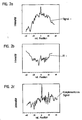
- the intensity profile of a reference pulse signal which results at a relative position of scale and scanning unit designated "0" with distributions chosen according to the invention, is shown in FIG. 2a.
- a sufficient signal intensity or sufficient useful signal component at the position "0" of scale and scanning unit is ensured.
- inventively embodied optical position measuring not only at a single defined relative position of mutually movable parts having such structures for generating a Reference pulse signals are equipped; it is rather possible to different positions of the scale corresponding fields with reference pulse scale structures M to arrange according to Figure 1.
- the aim of the optimization method is here that the distributions of permeable in the case of a transmitted light variant and non-transmissive regions S U , S D , M U , M D , A U , A D on the part of the various structures S, M and A at the relative position "0" to be detected ensure a reference pulse signal of sufficient intensity. Any resulting secondary maxima should be suppressed as much as possible because of the required detection reliability for the reference pulse signal.
- the emission characteristic of a divergent light source LQ ie the corresponding parameters
- the emission characteristic of a divergent light source LQ is determined in the first step S1.
- two of the three irregular distributions of regions with different optical properties are arbitrarily set.
- the distribution of the different regions for the reference pulse transmission structure S and the distribution for the reference pulse scale structure M can be specified as start structures. In principle, however, two other structures could be given arbitrarily.
- the resulting intensity distribution in a detector plane is numerically modeled or determined in the subsequent step S3 of the optimization method.
- the determination of the resulting intensity distribution in step S3 is based on a position-measuring device which is operated in the shadow.
- a position-measuring device which is operated in the shadow.
- the distribution of the regions of different optical properties on the side of the reference pulse scanning structure A is optimized taking into account individual so-called merit criteria in step S4. Accordingly, the third distribution of the reference pulse scanning structure A, which has not hitherto been predetermined, is optimized as a function of the two predetermined starting structures S, M.
- Suitable merit criteria for the optimization of the third distribution A are, for example, the greatest possible degree of modulation of the reference pulse signal and / or the resulting useful component of the reference pulse signal in the detector plane.
- the intensity distribution of the reference pulse signal in the detector plane is considered, while the distribution of the regions of different optical properties on the side of the reference pulse scanning structure A is varied.
- step S5 in each case a check is made to what extent the current combination of the three distributions and the resulting reference pulse signal satisfy a specific termination criterion. If this is the case, the optimization method is aborted and the corresponding distributions for the regions with different optical properties of the three structures S, M and A are output in step S6. If the predetermined termination criteria can not be met by optimizing the third distribution or structure, in the next run of the algorithm in step S2 one of the start structures is varied and one of the other structures is optimized in the manner described.
- the three distributions of the regions of the reference pulse transmission structure S, the reference momentum scale M as well the reference pulse scanning structure A are optimized step by step until the resulting reference pulse signal corresponds to the specified requirements.
- Reference impulse transmission structure 11 ranges, width each 40 ⁇ m permeable areas: 1, 4, 6, 10
- Reference momentum scale structure 45 areas, width 20 ⁇ m each) permeable areas: 1, 3, 5, 6, 7, 8, 9, 14, 15, 17, 19, 21, 24, 28, 33, 34, 35, 39, 40, 43, 44
- Reference pulse scanning structure 23 areas, 40 ⁇ m each) permeable areas: 1, 2, 5, 7, 8, 10, 12, 15, 20, 21, 22, 23
- the numbers listed in Table 1a give the distributions the reference impulse transmission structure, scale structure and scanning structure are assigned, the numbers of the permeable sections of the respective Structure, if these structures in a number of equally wide sub-areas be divided.
- the totality of the respective subareas forms one field each.
- the Field with the reference pulse scale structure comprises 45 sections, the each 20 ⁇ m wide.
- the field with the reference pulse sample structure has 20 sections, each 40 ⁇ m wide.
- this embodiment was furthermore each of a distance of 0.7mm between the light source and the reference pulse transmission structure, between the reference pulse transmission structure and reference pulse scale structure as well as between Reference Pulse Scale Structure and Reference Pulse Scan Structure went out.
- the variant shown in Table 1a for the three distributions of the areas on the side of the reference pulse structures S, M and A delivers about 20 ⁇ m wide reference pulse signal for incremental division with one division period of 20 ⁇ m.
- Reference impulse transmission structure 11 ranges, width each 40 ⁇ m
- Reference momentum scale structure 45 areas, width 20 ⁇ m each
- Reference pulse scanning structure 23 areas, 40 ⁇ m each) permeable areas: 3, 4, 9, 11, 13, 14, 18, 19
- a further, second reference pulse signal generate the following as a complementary signal to the first Reference pulse signal is called.
- the first shown in Figure 2b Example of a complementary reference pulse signal can also be called Pseudo push-pull signal are called.
- the detection reliability with respect to this signal can be increased, in particular the signal-to-noise ratio can be increased.
- the now increased useful component of the resulting reference pulse signal can be clearly seen in comparison to the two individual signals in FIGS. 2a and 2b.
- Another way to create a second, complementary Reference pulse signals is the reference pulse scale structures of the complementary, second reference pulse signal inverse to the Form reference pulse scale structures of the first reference pulse signal.
- the generation of the complementary, second reference pulse signal corresponds to the well-known formation of a so-called “real" Push-pull reference pulse signal.
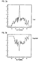
- the signal course of a first reference pulse signal generated according to the invention is shown in FIG. 3a.
- a second embodiment with respect. is the generation of a complementary, second reference pulse signal shown in Figure 3b, now as explained above as a "real" push-pull reference pulse signal educated.
- Reference impulse transmission structure (15 ranges, width each 40 ⁇ m) permeable areas: 1, 2, 4, 5, 7, 9, 11, 14, 15
- Reference momentum scale structure 45 areas, width 20 ⁇ m each) permeable areas: 1, 5, 6, 8, 16, 17, 21, 23, 25, 29, 34, 35, 36, 45
- Reference pulse scanning structure 23 areas, 40 ⁇ m each) permeable areas: 1, 9, 13, 19, 22, 23
- a "true" push-pull reference pulse signal according to FIG. 3b results on the basis of distributions for the different structures according to the following table 2b.
- Reference impulse transmission structure (15 ranges, width each 40 ⁇ m) permeable areas: 1, 2, 4, 5, 7, 9, 11, 14, 15
- Reference momentum scale structure 45 areas, width 20 ⁇ m each) permeable areas: 2, 3, 4, 7, 9, 10, 11, 12, 13, 14, 15, 18, 19, 20, 22, 24, 26, 27, 28, 30, 31, 32, 33, 37 , 38, 39, 40, 41, 42, 43, 44
- Reference pulse scanning structure 23 areas, 40 ⁇ m each) permeable areas: 1, 9, 13, 19, 22, 23
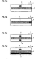
- a reference pulse scale structure M designed according to the invention is arranged laterally adjacent to an incremental graduation IT, ie perpendicular to the measuring direction x.
- a reference pulse scanning structure designed according to the invention is mounted on the side of the scanning unit laterally adjacent to the incremental scanning graduation.
- FIG. 5b An alternative possibility, the reference pulse scale structure formed according to the invention to arrange is shown in Figure 5b. There is provision at least one corresponding reference pulse scale structure M at one end of the incremental pitch IT.
- reference pulse scale structure M immediately to integrate into the incremental IT and design the scan side suitable.
- reference pulse scale structures M, M ' which is a first and a second or complementary reference pulse signal generate at a defined relative position is shown in Figure 5c.
- the two reference pulse scale structures M, M ' are in each case laterally adjacent to the incremental graduation IT arranged on the scale.
- the two reference pulse scale structures M, M ' can be approximately identical as formed in the embodiments of Tables 1a and 1b be. However, according to Tables 1a and 1b, the differences are associated reference pulse sampling structures on the side of - not shown Scanning unit is designed to scan by the reference pulse scale structure a complementary second reference pulse signal produce.
- the two reference pulse scale structures can also be used be formed differently while required for scanning Reference pulse transmitting and Abtast Modellen identically formed are, i. this variant provides reference pulse signals accordingly Figures 3a and 3b based on the distributions in Tables 2a and 2b.
- Figures 5b, 5c and 5d prove are advantageous in terms of their moiré insensitivity. This means, that even with a possible rotation of the scanning unit about an axis perpendicular to the measuring direction x, a reference pulse signal at the desired Position results.
- reference pulse scale structures can also be used M and M 'are arranged laterally adjacent to the incremental graduation IT in a known manner a clock and push-pull reference pulse signal deliver.
- the respective reference pulse structures inversely to each other, i. at the same x positions are provided in one of the two fields permeable areas while in the other field there impermeable areas are arranged etc.
- FIGS. 5a-5d may be both by standards for transmitted light as well as incident light variants of the invention act optical position measuring. Depending on is a permeable or a reflective incremental IT division to use.
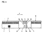
- FIG. 10 Another embodiment of the optical position measuring device according to the invention is shown in a schematic representation in FIG. this is a reflected-light version of the same. Visible are in the plan view according to Figure 6 while a stationary arranged Scale 10 and a relative, in the measuring direction x, this movable Scanning unit 20.
- the scale 10 consists of a graduation carrier 1, preferably of glass or steel, on the measuring direction x an incremental graduation 2 is arranged with a defined pitch period TP.
- Area of the scale 10 is further a field on the graduation carrier 1 recognizable that the inventively formed reference pulse scale structure 3 contains.
- Both the incremental division 2 and the reference momentum scale structure 3 are in this embodiment of the position measuring device according to the invention as an alternating sequence of reflective and nonreflective Areas trained.
- the longitudinal direction of the areas with different optical properties is perpendicular in the plane of the drawing oriented to the measuring direction x.
- the scanning unit comprises 20 a light source 5, preferably formed as LED.
- a light source 5 preferably formed as LED.
- the arrangement of the detector elements 9a-9d takes place in this way, that thus in each case by 90 ° out of phase scanning signals generated are.
- a translucent support member 4 are further - in Figure 6 unrecognizable - structuring provided in the area before the light source 5 act as a transmission structure and in the area in front of the photosensitive Detector surfaces as sampling structures for the incremental graduation 2 act.
- the contacting of the detector elements 9a - 9d and the light source 5 takes place by means of a printed circuit board, also not shown, via in addition also the mechanical stabilization of the scanning unit 20 takes place.
- a further light source 6 is provided on the side of the scanning unit 20, which is likewise arranged on the carrier element 4 and can be contacted by means of a printed circuit board or a flexible conductor strip. Laterally adjacent to the light source 6, two detector elements 10a, 10b can be seen, via which a first and a second reference pulse signal can be detected. In this case, reference pulse signals complementary to each other are detected via the two detector elements 10a, 10b, which can be generated in accordance with the previously explained principles.
- the reference pulse transmission structure is arranged on the carrier element 4 of the scanning unit in the region in front of the light source 6. Also on the support member 4, the reference pulse scanning structures are mounted in front of the photosensitive surfaces of the detector elements 10, 10b. The distributions of the optically transmissive and non-transmissive regions in the reference pulse transmission, scale and sampling structures have in turn been matched according to the optimization method explained above.
- the illustrated in Figure 6 embodiment of the optical position measuring device according to the invention ensures a particularly compact design and allows the generation of high-resolution reference pulse signals.
- alternative embodiments are feasible within the scope of the inventive considerations.
- only a single light source for generating the incremental signals and the reference pulse signals can be used on the part of the scanning unit.
- there are various possibilities with regard to the generation of two complementary reference pulse signals For example, the same transmission and scale structures, but different sampling structures can be used.
Landscapes
- Physics & Mathematics (AREA)
- General Physics & Mathematics (AREA)
- Optical Transform (AREA)
- Length Measuring Devices By Optical Means (AREA)
- Body Structure For Vehicles (AREA)
- Vehicle Body Suspensions (AREA)
- Eye Examination Apparatus (AREA)
Applications Claiming Priority (2)
| Application Number | Priority Date | Filing Date | Title |
|---|---|---|---|
| DE19726935 | 1997-06-25 | ||
| DE19726935.4A DE19726935B4 (de) | 1997-06-25 | 1997-06-25 | Optische Positionsmeßeinrichtung |
Publications (3)
| Publication Number | Publication Date |
|---|---|
| EP0887625A2 EP0887625A2 (de) | 1998-12-30 |
| EP0887625A3 EP0887625A3 (de) | 2000-10-04 |
| EP0887625B1 true EP0887625B1 (de) | 2005-12-07 |
Family
ID=7833583
Family Applications (1)
| Application Number | Title | Priority Date | Filing Date |
|---|---|---|---|
| EP98110401A Expired - Lifetime EP0887625B1 (de) | 1997-06-25 | 1998-06-06 | Optische Positionsmesseinrichtung |
Country Status (5)
| Country | Link |
|---|---|
| US (1) | US6097490A (enExample) |
| EP (1) | EP0887625B1 (enExample) |
| JP (1) | JP4303804B2 (enExample) |
| AT (1) | ATE312335T1 (enExample) |
| DE (2) | DE19726935B4 (enExample) |
Families Citing this family (15)
| Publication number | Priority date | Publication date | Assignee | Title |
|---|---|---|---|---|
| EP0896206B1 (de) | 1997-08-07 | 2002-12-11 | Dr. Johannes Heidenhain GmbH | Abtasteinheit für eine optische Positionsmesseinrichtung |
| EP1003012B3 (de) | 1998-11-19 | 2011-04-20 | Dr. Johannes Heidenhain GmbH | Optische Positionsmesseinrichtung |
| EP1028309B1 (de) * | 1999-02-04 | 2003-04-16 | Dr. Johannes Heidenhain GmbH | Optische Positionsmesseinrichtung |
| DE19962278A1 (de) | 1999-12-23 | 2001-08-02 | Heidenhain Gmbh Dr Johannes | Positionsmeßeinrichtung |
| GB0103582D0 (en) | 2001-02-14 | 2001-03-28 | Renishaw Plc | Position determination system |
| DE10127239A1 (de) * | 2001-05-28 | 2002-12-12 | Inst Mikroelektronik Und Mecha | Verfahren und Computerprogrammprodukt zur Auswertung von durch Meßgeräte aufgenommenen Daten |
| US6723980B2 (en) * | 2001-07-16 | 2004-04-20 | Wai-Hon Lee | Position sensor with grating to detect moving object with periodic pattern |
| DE10217726A1 (de) * | 2002-04-17 | 2003-11-27 | Heidenhain Gmbh Dr Johannes | Optische Positionsmesseinrichtung |
| US7191943B2 (en) * | 2004-07-28 | 2007-03-20 | Caterpillar Inc | Robust barcode and reader for rod position determination |
| DE102005006247A1 (de) | 2005-02-11 | 2006-08-17 | Dr. Johannes Heidenhain Gmbh | Positionsmesseinrichtung |
| GB0523273D0 (en) * | 2005-11-16 | 2005-12-21 | Renishaw Plc | Scale and readhead apparatus and method |
| DE102006021484A1 (de) * | 2006-05-09 | 2007-11-15 | Dr. Johannes Heidenhain Gmbh | Optische Positionsmesseinrichtung |
| GB201301186D0 (en) | 2012-12-20 | 2013-03-06 | Renishaw Plc | Optical element |
| JP5853115B1 (ja) * | 2015-05-25 | 2016-02-09 | 株式会社Nttファシリティーズ | 変位計、位置検出方法及びプログラム |
| DE102018202556A1 (de) * | 2018-02-20 | 2019-08-22 | Dr. Johannes Heidenhain Gmbh | Optische Positionsmesseinrichtung |
Family Cites Families (13)
| Publication number | Priority date | Publication date | Assignee | Title |
|---|---|---|---|---|
| DE1814785A1 (de) * | 1968-12-14 | 1970-06-25 | Johannes Heidenhain Feinmechan | Zaehlanordnung |
| AT394275B (de) * | 1981-06-22 | 1992-02-25 | Rieder Heinz | Lagemesssystem, insbesondere inkrementales lagemesssystem |
| US4451731A (en) * | 1981-08-10 | 1984-05-29 | Hewlett-Packard Company | Apparatus and method for modulating light to generate an index pulse |
| US4678908A (en) * | 1983-07-25 | 1987-07-07 | Bei Electronics, Inc. | Zero reference generating method and apparatus for optical encoders |
| DE3509871C2 (de) * | 1985-03-19 | 1987-03-12 | Dr. Johannes Heidenhain Gmbh, 8225 Traunreut | Positionsmeßeinrichtung |
| JPS6347616A (ja) * | 1986-08-15 | 1988-02-29 | Ricoh Co Ltd | 移動量測定方法 |
| JP2549514B2 (ja) * | 1986-11-13 | 1996-10-30 | 株式会社 ソキア | 光電式エンコ−ダの基準点信号発生機構 |
| JPH07888Y2 (ja) * | 1988-02-22 | 1995-01-11 | 株式会社ミツトヨ | 光学式変位検出器 |
| US5065017A (en) * | 1990-04-20 | 1991-11-12 | Hoech Robert W | Zero mark for optical encoder using stator mask patterns and rotor patterns |
| CH683798A5 (fr) * | 1990-12-10 | 1994-05-13 | Tesa Sa | Capteur de position pour un appareil de mesure de grandeurs linéaires ou angulaires. |
| DE59102126D1 (de) * | 1991-05-18 | 1994-08-11 | Heidenhain Gmbh Dr Johannes | Interferentielle Positionsmessvorrichtung. |
| DE4212281A1 (de) * | 1991-07-11 | 1993-10-14 | Heidenhain Gmbh Dr Johannes | Interferentielle Positionsmeßvorrichtung |
| EP0635701B1 (de) * | 1993-07-17 | 1997-10-29 | Dr. Johannes Heidenhain GmbH | Längen- oder Winkelmesseinrichtung |
-
1997
- 1997-06-25 DE DE19726935.4A patent/DE19726935B4/de not_active Expired - Fee Related
-
1998
- 1998-06-06 DE DE59813254T patent/DE59813254D1/de not_active Expired - Lifetime
- 1998-06-06 EP EP98110401A patent/EP0887625B1/de not_active Expired - Lifetime
- 1998-06-06 AT AT98110401T patent/ATE312335T1/de not_active IP Right Cessation
- 1998-06-17 JP JP17029898A patent/JP4303804B2/ja not_active Expired - Fee Related
- 1998-06-23 US US09/103,327 patent/US6097490A/en not_active Expired - Lifetime
Also Published As
| Publication number | Publication date |
|---|---|
| DE19726935A1 (de) | 1999-01-07 |
| DE59813254D1 (de) | 2006-01-12 |
| JP4303804B2 (ja) | 2009-07-29 |
| DE19726935B4 (de) | 2014-06-12 |
| ATE312335T1 (de) | 2005-12-15 |
| EP0887625A3 (de) | 2000-10-04 |
| EP0887625A2 (de) | 1998-12-30 |
| JPH1183432A (ja) | 1999-03-26 |
| US6097490A (en) | 2000-08-01 |
Similar Documents
| Publication | Publication Date | Title |
|---|---|---|
| EP0896206B1 (de) | Abtasteinheit für eine optische Positionsmesseinrichtung | |
| EP0887625B1 (de) | Optische Positionsmesseinrichtung | |
| EP0509979B1 (de) | Photoelektronische Positionsmesseinrichtung | |
| EP0513427B1 (de) | Interferentielle Positionsmessvorrichtung | |
| DE19748802B4 (de) | Optische Positionsmeßeinrichtung | |
| EP1081457B1 (de) | Optische Positionsmesseinrichtung | |
| EP1396704B1 (de) | Interferenzielle Positionsmesseinrichtung | |
| EP1923673B1 (de) | Positionsmesseinrichtung | |
| EP0160811B1 (de) | Photoelektrische Messeinrichtung | |
| EP1003012B3 (de) | Optische Positionsmesseinrichtung | |
| EP1407231B1 (de) | Positionsmesseinrichtung | |
| WO2008138501A1 (de) | Positionsmesseinrichtung | |
| DE102008007319A1 (de) | Optische Positionsmesseinrichtung | |
| EP3064902B1 (de) | System zur bestimmung von positionen | |
| DE19754595B4 (de) | Lichtelektrische Positionsmeßeinrichtung | |
| EP0669519A2 (de) | Positionsmessvorrichtung | |
| EP2404143A2 (de) | Positionsmesseinrichtung | |
| EP0763715B1 (de) | Vorrichtung zur Filterung von Oberwellen-Signalanteilen | |
| EP1028309A1 (de) | Optische Positionsmesseinrichtung | |
| EP1279005B1 (de) | Abtasteinheit für eine optische positionsmesseinrichtung | |
| EP1427985A1 (de) | Positionsmesseinrichtung und verfahren zum betrieb einer positionsmesseinrichtung | |
| EP2878930B1 (de) | Positionsmesseinrichtung | |
| DE10116599A1 (de) | Optische Positionsmesseinrichtung | |
| DE19936181A1 (de) | Optische Positionsmeßeinrichtung | |
| EP0434973B1 (de) | Lichtelektrische Positionsmesseinrichtung |
Legal Events
| Date | Code | Title | Description |
|---|---|---|---|
| PUAI | Public reference made under article 153(3) epc to a published international application that has entered the european phase |
Free format text: ORIGINAL CODE: 0009012 |
|
| AK | Designated contracting states |
Kind code of ref document: A2 Designated state(s): AT CH DE FR GB IT LI |
|
| AX | Request for extension of the european patent |
Free format text: AL;LT;LV;MK;RO;SI |
|
| PUAL | Search report despatched |
Free format text: ORIGINAL CODE: 0009013 |
|
| AK | Designated contracting states |
Kind code of ref document: A3 Designated state(s): AT BE CH CY DE DK ES FI FR GB GR IE IT LI LU MC NL PT SE |
|
| AX | Request for extension of the european patent |
Free format text: AL;LT;LV;MK;RO;SI |
|
| 17P | Request for examination filed |
Effective date: 20010404 |
|
| AKX | Designation fees paid |
Free format text: AT CH DE FR GB IT LI |
|
| GRAP | Despatch of communication of intention to grant a patent |
Free format text: ORIGINAL CODE: EPIDOSNIGR1 |
|
| GRAS | Grant fee paid |
Free format text: ORIGINAL CODE: EPIDOSNIGR3 |
|
| GRAA | (expected) grant |
Free format text: ORIGINAL CODE: 0009210 |
|
| AK | Designated contracting states |
Kind code of ref document: B1 Designated state(s): AT CH DE FR GB IT LI |
|
| REG | Reference to a national code |
Ref country code: GB Ref legal event code: FG4D Free format text: NOT ENGLISH |
|
| REG | Reference to a national code |
Ref country code: CH Ref legal event code: NV Representative=s name: TROESCH SCHEIDEGGER WERNER AG Ref country code: CH Ref legal event code: EP |
|
| GBT | Gb: translation of ep patent filed (gb section 77(6)(a)/1977) |
Effective date: 20051207 |
|
| REF | Corresponds to: |
Ref document number: 59813254 Country of ref document: DE Date of ref document: 20060112 Kind code of ref document: P |
|
| ET | Fr: translation filed | ||
| PLBE | No opposition filed within time limit |
Free format text: ORIGINAL CODE: 0009261 |
|
| STAA | Information on the status of an ep patent application or granted ep patent |
Free format text: STATUS: NO OPPOSITION FILED WITHIN TIME LIMIT |
|
| 26N | No opposition filed |
Effective date: 20060908 |
|
| PG25 | Lapsed in a contracting state [announced via postgrant information from national office to epo] |
Ref country code: AT Free format text: LAPSE BECAUSE OF NON-PAYMENT OF DUE FEES Effective date: 20060606 |
|
| PGFP | Annual fee paid to national office [announced via postgrant information from national office to epo] |
Ref country code: FR Payment date: 20100706 Year of fee payment: 13 |
|
| PGFP | Annual fee paid to national office [announced via postgrant information from national office to epo] |
Ref country code: IT Payment date: 20100625 Year of fee payment: 13 |
|
| PGFP | Annual fee paid to national office [announced via postgrant information from national office to epo] |
Ref country code: CH Payment date: 20100623 Year of fee payment: 13 |
|
| REG | Reference to a national code |
Ref country code: CH Ref legal event code: PL |
|
| PG25 | Lapsed in a contracting state [announced via postgrant information from national office to epo] |
Ref country code: IT Free format text: LAPSE BECAUSE OF NON-PAYMENT OF DUE FEES Effective date: 20110606 |
|
| REG | Reference to a national code |
Ref country code: FR Ref legal event code: ST Effective date: 20120229 |
|
| PG25 | Lapsed in a contracting state [announced via postgrant information from national office to epo] |
Ref country code: CH Free format text: LAPSE BECAUSE OF NON-PAYMENT OF DUE FEES Effective date: 20110630 Ref country code: LI Free format text: LAPSE BECAUSE OF NON-PAYMENT OF DUE FEES Effective date: 20110630 Ref country code: FR Free format text: LAPSE BECAUSE OF NON-PAYMENT OF DUE FEES Effective date: 20110630 |
|
| PGFP | Annual fee paid to national office [announced via postgrant information from national office to epo] |
Ref country code: GB Payment date: 20140618 Year of fee payment: 17 |
|
| PGFP | Annual fee paid to national office [announced via postgrant information from national office to epo] |
Ref country code: DE Payment date: 20150619 Year of fee payment: 18 |
|
| GBPC | Gb: european patent ceased through non-payment of renewal fee |
Effective date: 20150606 |
|
| PG25 | Lapsed in a contracting state [announced via postgrant information from national office to epo] |
Ref country code: GB Free format text: LAPSE BECAUSE OF NON-PAYMENT OF DUE FEES Effective date: 20150606 |
|
| REG | Reference to a national code |
Ref country code: DE Ref legal event code: R119 Ref document number: 59813254 Country of ref document: DE |
|
| PG25 | Lapsed in a contracting state [announced via postgrant information from national office to epo] |
Ref country code: DE Free format text: LAPSE BECAUSE OF NON-PAYMENT OF DUE FEES Effective date: 20170103 |