EP0887460B2 - Process and apparatus to clean a transport band - Google Patents
Process and apparatus to clean a transport band Download PDFInfo
- Publication number
- EP0887460B2 EP0887460B2 EP98108953A EP98108953A EP0887460B2 EP 0887460 B2 EP0887460 B2 EP 0887460B2 EP 98108953 A EP98108953 A EP 98108953A EP 98108953 A EP98108953 A EP 98108953A EP 0887460 B2 EP0887460 B2 EP 0887460B2
- Authority
- EP
- European Patent Office
- Prior art keywords
- cleaning
- transport belt
- cleaned
- conveyor belt
- width
- Prior art date
- Legal status (The legal status is an assumption and is not a legal conclusion. Google has not performed a legal analysis and makes no representation as to the accuracy of the status listed.)
- Expired - Lifetime
Links
Images
Classifications
-
- D—TEXTILES; PAPER
- D21—PAPER-MAKING; PRODUCTION OF CELLULOSE
- D21F—PAPER-MAKING MACHINES; METHODS OF PRODUCING PAPER THEREON
- D21F1/00—Wet end of machines for making continuous webs of paper
- D21F1/32—Washing wire-cloths or felts
- D21F1/325—Washing wire-cloths or felts with reciprocating devices
-
- D—TEXTILES; PAPER
- D21—PAPER-MAKING; PRODUCTION OF CELLULOSE
- D21F—PAPER-MAKING MACHINES; METHODS OF PRODUCING PAPER THEREON
- D21F1/00—Wet end of machines for making continuous webs of paper
- D21F1/32—Washing wire-cloths or felts
Landscapes
- Cleaning By Liquid Or Steam (AREA)
- Cleaning In General (AREA)
- Structure Of Belt Conveyors (AREA)
- Belt Conveyors (AREA)
Description
Die Erfindung betrifft ein Verfahren zum Reinigen eines Transportbandes einer Maschine zur Herstellung einer Materialbahn, insbesondere Papier- oder Kartonbahn, gemäß Oberbegriff des Anspruchs 1 bzw. 2.The invention relates to a method for cleaning a conveyor belt of a machine for producing a material web, in particular paper or board web, according to the preamble of claim 1 or 2.
In Maschinen zur Herstellung einer Materialbahn werden zahlreiche Transportbänder, insbesondere Gewebebänder, eingesetzt. Diese werden während des laufenden Betriebs der Maschine verunreinigt, beispielsweise durch Fasern der Materialbahn, Klebstoffe oder sonstigen Zuschlagstoffe, die die Maschen und Poren der Transportbänder zusetzen. Um einen störungsfreien Produktionsablauf gewährleisten zu können, werden die Transportbänder mittels einer Reinigungsvorrichtung gereinigt. Es sind Reinigungsvorrichtungen bekannt, die eine mit einem unter Druck stehenden Reinigungsmedium beaufschlagbare Düse umfassen. Die Düse ist quer zur Laufrichtung des Transportbandes verlagerbar und bringt das Reinigungsmedium gleichmäßig auf die Transportbandoberfläche auf. Weiterhin sind Reinigungsvorrichtungen bekannt, die einen sich quer zur Laufrichtung des Transportbandes erstreckenden Düsenbalken umfassen, an dem mehrere Düsen angebracht sind, mittels derer ein Reinigungsmedium auf das Transportband aufgebracht werden kann. Es hat sich gezeigt, daß die Transportbänder -quer zur Laufrichtung gesehen- ungleichmäßig stark verunreinigt werden, das heißt, das Transportband kann beispielsweise in den Randbereichen besonders stark verschmutzt sein, während in der Transportbandmitte lediglich eine geringe Verschmutzung gegeben sein kann. Die gleichmäßige Reinigungswirkung der bekannten Reinigungsvorrichtungen kann in solchen Fällen nicht immer ein zufriedenstellendes Reinigungsergebnis erbringen, was zu Störungen des Produktionsablaufs und insbesondere zu einem Qualitäts# verlust des fertigen Produkts führen kann (siehe EP-A-383486).In machines for producing a material web, numerous conveyor belts, in particular woven belts, are used. These are contaminated during operation of the machine, for example by fibers of the web, adhesives or other additives that enforce the mesh and pores of the conveyor belts. In order to ensure a trouble-free production process, the conveyor belts are cleaned by means of a cleaning device. There are cleaning devices are known which comprise a pressurizable with a pressurized cleaning medium nozzle. The nozzle is displaceable transversely to the direction of the conveyor belt and brings the cleaning medium evenly on the conveyor belt surface. Furthermore, cleaning devices are known which comprise a transversely extending to the direction of the conveyor belt nozzle bar, are mounted on the plurality of nozzles, by means of which a cleaning medium can be applied to the conveyor belt. It has been shown that the conveyor belts-transverse to the running direction- are unevenly contaminated, that is, the conveyor belt may be particularly heavily soiled, for example, in the edge regions, while only a small contamination can be given in the conveyor belt center. The uniform cleaning effect of the known cleaning devices can not always provide a satisfactory cleaning result in such cases, which can lead to disruptions in the production process and in particular to a loss of quality # of the finished product (see EP-A-383486).
Es ist daher Aufgabe der Erfindung, ein Verfahren zu schaffen, das diesen Nachteil nicht aufweist.It is therefore an object of the invention to provide a method which does not have this disadvantage.
Zur Lösung dieser Aufgabe wird ein Verfahren vorgeschlagen, das die in Anspruch 1 bzw. 2 genannten Merkmale aufweist. Es zeichnet sich dadurch aus, daß das Transportband über die Breite mit unterschiedlicher Intensität gereinigt wird. Das Transportband wird während eines Reinigungsvorgangs -quer zur Laufrichtung des Transportbandes gesehen- an verschiedenen Stellen mit jeweils einer definierten, vorzugsweise an den Verschmutrungsgrad des jeweiligen Transportbandabschnitts angepaßten Intensität gereinigt. Es ist aber auch möglich, daß grundsätzlich die Ränder des Transportbandes mit einer größeren Intensität gereinigt werden, als der dazwischenliegende Transportbandabschnitt oder umgekehrt. Durch das Reinigen des Transportbandes mit unterschiedlicher Intensität kann ein besonders gutes Reinigungsergebnis erzielt werden, so daß eine Störung des Produktionsablaufs durch ein nicht ausreichend gründlich gereinigtes Transportband praktisch ausgeschlossen werden kann. Weiterhin kann der Verbrauch des Reinigungsmediums verringert werden.To solve this problem, a method is proposed, which has the features mentioned in claim 1 or 2. It is characterized in that the conveyor belt is cleaned across the width with different intensity. The conveyor belt is cleaned during a cleaning process - seen transverse to the direction of the conveyor belt - at different locations, each with a defined, preferably adapted to the degree of contamination of the respective conveyor belt section intensity. But it is also possible that in principle the edges of the conveyor belt are cleaned with a greater intensity than the intermediate conveyor belt section or vice versa. By cleaning the conveyor belt with different intensity, a particularly good cleaning result can be achieved, so that a disruption of the production process by a not sufficiently thoroughly cleaned conveyor belt can be practically eliminated. Furthermore, the consumption of the cleaning medium can be reduced.
Dabei wird die Reinigungsintensität durch eine gezielte Vorgabe der Zeitdauer beeinflußt, in der ein definierter Bereich des Transportbandes gereinigt wird. In einer anderen Ausführungsform der Erfindung ist vorgesehen, daß die Reinigungsintensität durch Einstellen des zwischen zwei aufeinanderfolgenden Reinigungsvorgängen liegenden Zeitintervalls beeinflußt wird, in dem ein und derselbe Bereich des Transportbandes gereinigt wird. Die Reinigungsintensität wird um so höher, desto länger die Zeitdauer der Reinigung und/oder je kürzer das Zeitintervall zwischen zwei Reinigungsvorgängen ist.The cleaning intensity is influenced by a specific specification of the time duration in which a defined area of the conveyor belt is cleaned. In another embodiment of the invention, it is provided that the cleaning intensity is influenced by adjusting the interval of time between two successive cleaning operations, in which one and the same area of the conveyor belt is cleaned. The cleaning intensity is higher, the longer the duration of the cleaning and / or the shorter the time interval between two cleaning operations.
Es wird eine Ausführungsform des Verfahrens bevorzugt, die sich dadurch auszeichnet, daß das Transportband mit einem unter Druck stehenden, gasförmigen oder flüssigen Reinigungsmedium gereinigt wird und daß die Reinigungsintensität durch Einstellen des Drucks des Reinigungsmediums beeinflußt wird. Je größer der Druck des Reinigungsmediums ist, desto höher kann die Reinigungswirkung werden und umgekehrt. Dadurch können lediglich gering verschmutzte Transportbandbereiche mit einem unter einem geringeren Druck stehenden Reinigungsmedium und die stärker verschmutzten Transportbandbereiche mit einem unter einem entsprechend höheren Druck stehenden Reinigungsmedium beaufschlagt werden. Durch einen geringen Druck des Reinigungsmediums wird das Transportband einer relativ kleinen Beanspruchu ng unterworfen, was insbesondere bei empfindlichen Transportbändern deren Lebensdauer verlängert.It is preferred an embodiment of the method, which is characterized in that the conveyor belt is cleaned with a pressurized, gaseous or liquid cleaning medium and that the cleaning intensity is influenced by adjusting the pressure of the cleaning medium. The greater the pressure of the cleaning medium, the higher the cleaning effect can be and vice versa. As a result, only slightly contaminated conveyor belt areas can be acted upon by a cleaning medium under a lower pressure and the more heavily soiled conveyor belt areas with a cleaning medium under a correspondingly higher pressure. By a low pressure of the cleaning medium, the conveyor belt is subjected to a relatively small load, which prolongs its service life, especially in the case of sensitive conveyor belts.
Besonders bevorzugt wird eine Ausführungsform des Verfahrens, die sich dadurch auszeichnet, daß der Reinigungsbereich des Transportbandes mit Unterdruck beaufschlagt wird und daß der Druck in Abhängigkeit von der gewünschten Reinigungsintensität eingestellt wird. Mit zunehmenden Unterdruck kann auch besonders hartnäckig an dem Transportband haftender Schmutz sicher abgelöst werden, so daß ein gewü nschtes Reinigungsergebnis erzielt wird. Besonders vorteilhaft bei der Steuerung der Besaugung ist, daß dadurch der Unterdruckbedarf und somit die Kosten für dessen Bereitstellung verringert werden können.Particularly preferred is an embodiment of the method, which is characterized in that the cleaning region of the conveyor belt is subjected to negative pressure and that the pressure is adjusted in dependence on the desired cleaning intensity. With increasing negative pressure can also be particularly persistently detached on the conveyor belt adhering dirt, so that a gewü desired cleaning result is achieved. Particularly advantageous in the control of the aspiration that thereby the vacuum requirements and thus the cost of its provision can be reduced.
Schließlich wird eine Ausführungsform des Verfahrens bevorzugt, die sich dadurch auszeichnet, daß die auf den zu reinigenden Transportbandbereich aufgebrachte Menge des Reinigungsmediums eingestellt wird. Die Reinigungswirkung kann mit größerwerdender Menge des auf das Transportband aufgebrachten Reinigungsmediums ansteigen. Durch die Vorgabe der für die Reinigung des Transportbandes eingesetzten Menge des flüssigen oder gasförmigen Reinigungsmediums, beispielsweise in Abhängigkeit des Verschmutzungsgrades des zu reinigenden Transportbandbereichs, kann die für eine gründliche Reinigung benötigte Menge des Reinigungsmediums reduziert werden.Finally, an embodiment of the method is preferred, which is characterized in that the applied to the conveyor belt area to be cleaned amount of the cleaning medium is adjusted. The cleaning effect can with increasing amount of applied to the conveyor belt Increase cleaning medium. By specifying the amount of liquid or gaseous cleaning medium used for cleaning the conveyor belt, for example, depending on the degree of soiling of the conveyor belt area to be cleaned, the amount of cleaning medium required for a thorough cleaning can be reduced.
Weitere vorteilhafte Ausführungsformen ergeben sich aus den übrigen Unteransprüchen.Further advantageous embodiments will be apparent from the remaining dependent claims.
Das erfindungsgemäße Verfahren nach einem der Ansprüche 1 bis 7 wird auch zum Einstellen des Feuchteprofils des Transportbandes verwendet. Dadurch, daß das Transportband -quer zu dessen Laufrichtung betrachtet- abschnitts-/bereichsweise mit unterschiedlicher Intensität gereinigt wird, kann der Feuchtegehalt im Transportband eingestellt werden. Dadurch kann das Feuchteprofil einer Materialbahn, die nach der Reinigung des Transportbandes von diesem gestützt wird, beeinflußt und vorzugsweise ebenfalls eingestelltwerden. Die Einstellung des Feuchteprofils, also des Wassergehalts des Transportbandes/der Materialbahn -quer zu dessen/deren Laufrichtung gesehen-erfolgt nach einem vorgegebenen Profil, wobei die Intensität der Reinigung des Transportbandes entsprechend angepaßt wird.The inventive method according to any one of claims 1 to 7 is also used for adjusting the moisture profile of the conveyor belt. As a result of the fact that the conveyor belt, viewed transverse to its direction of travel, is cleaned with different intensities in sections / areas, the moisture content in the conveyor belt can be adjusted. As a result, the moisture profile of a material web, which is supported by the cleaning of the conveyor belt, influenced by this, and preferably also be adjusted. The setting of the moisture profile, so the water content of the conveyor belt / the material web-transverse to the / seen its direction of rotation-takes place according to a predetermined profile, wherein the intensity of the cleaning of the conveyor belt is adjusted accordingly.
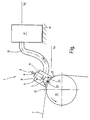
Die Erfindung wird im folgenden anhand einer einzigen Figur näher erläutert Diese zeigt eine schematische Seitenansicht einer Vorrichtung zum Reinigen eines Transportbandes einer nicht dargestellten Maschine zur Herstellung einer Materialbahn. Die Vorrichtung wird im folgenden kurz als Reinigungsvorrichtung 1 bezeichnet.The invention is explained in more detail below with reference to a single figure. This shows a schematic side view of an apparatus for cleaning a conveyor belt of a machine, not shown, for producing a material web. The device will hereinafter be referred to as cleaning device 1 for short.
Die Reinigungsvorrichtung 1 kann für belieblge Transportbänder einer Maschine zur Herstellung einer Materialbahn eingesetzt werden, beispielsweise für Siebbänder beziehungsweise Filze einer Sieb- beziehungsweise einer Pressen- oder Trockenpartie einer Papier- oder Kartonherstellungsmaschine. Mit dem Begriff "Transportbänder" sind auch die Siebe oder Filze angesprochen, die innerhalb eines der Pressen- und der Trockenpartie vorgeordneten Formers eingesetzt werden. Rein beispielhaft wird davon ausgegangen, daß es sich hier um Transportbänder einer Papierherstellungsmaschine handelt.The cleaning device 1 can be used for any conveyor belts of a machine for producing a material web, for example, for screen belts or felts a screening or a press or dryer section of a paper or board making machine. The term "conveyor belts" also the screens or felts are addressed, which are used within one of the press and the dryer section upstream Former. Purely by way of example, it is assumed that these are conveyor belts of a papermaking machine.
Die Reinigungsvorrichtung 1 umfaßt eine einen Düsenkopf 3 aufweisende Düseneinrichtung 5. Der Düsenkopf 3 weist mindestens eine -nicht dargestellte-Düse auf, die ein poröses Transportband 7 mit einem flüssigen Reinigungsmedium, beispielsweise Wasser, oder einem gasförmigen Reinigungsmedium, beispielsweise Dampf, beaufschlagt Im folgenden wird beispielhaft davon ausgegangen, daß es sich bei dem Reinigungsmedium um eine Flüssigkeit handelt, die unter einem Druck von 100 bar bis 1000 bar steht Weiterhin ist ein in der Figur teilweise dargestellter Anschluß 6 vorgesehen, an den ein mit einer Pumpe verbindbarer Druckschlauch zur Versorgung der Düseneinrichtung 5 mit dem Reinigungsmedium angeschlossen werden kann.The cleaning device 1 comprises a
In einem anderen Ausführungsbeispiel kann der Düsenkopf 3 um seine Längsachse 9 rotierbar ausgebildet werden und eine Düsenanordnung aufweisen, die eine oder mehrere Treibdüsen umfaßt, aus denen das Reinigungsmedium tangential zur Transportbandoberfläche austritt und die der Erzeugung einer Rotationsbewegung dienen, außerdem eine oder mehrere Reinigungsdüsen, die das Transportband mit dem Reinigungsmedium beaufschlagen. Die Rotation des Düsenkopfes kann auch auf andere Weise als durch die Verwendung von Treibdüsen bewirkt werden.In another embodiment, the
Die Düseneinrichtung 5 ist von einer mantelförmigen Saugglocke 11 vollständig umgeben. Das Innere der Saugglocke 11 ist mit einer Absaugleitung 13 verbunden und bildet einen der Düseneinrichtung 5 zugeordneten Saugraum 15. Die Absaugleitung 13 wird an einem Traversierwagen 17 angebracht und steht mit einer nicht dargestellten Unterdruckquelle in Strömungsverbindung. Der Traversierwagen 17 ist entlang einer sich quer zur Laufrichtung des Transportbandes 7 erstreckenden -stark schematisiert dargestellten- Traverse 19 verlagerbar. Der Traversierwagen 17 und die Traverse 19 bilden eine Traversiereinheft 20.The
Wie aus der Figur ersichtlich, ist die Reinigungsvorrichtung, 1 einer Umlenkrolle 21 zugeordnet, um die das Transportband 7 herumgeführt wird. Die sich über einen Teilbereich der Umfangsfläche der Umlenkrolle 21 erstreckende Saugglocke 11 ist in einem Abstand zur Umlenkrolle 21 angeordnet. Ein dem Transportband 7 zugewandter Endbereich 23 der Saugglocke 11 ist der kreiszylindrischen Umfangsform der Umlenkrolle 21 angepaßt, so daß der Spalt zwischen der Saugglocke 11 und dem Transportband 7 im wesentlichen konstant ist. Der Abstand zwischen der Saugglokke 11 und dem Transportband 7 ist einstellbar, worauf noch näher eingegangen wird.As can be seen from the figure, the cleaning device 1 is associated with a
Im folgenden wird die Funktionsweise der Reinigungsvorrichtung 1 näher erläutert. Das über die Umlenkrolle 21 geführte Transportband 7 wird von der Düseneinrichtung 5 mit unter Druck stehender Reinigungsflüssigkeit (Düsenstrahl 25) beaufschlagt. Hierbei werden Grobpartikel und Schmutz vom Transportband 7 gelöst und durch die Saugglocke 11 von der Oberfläche des Transportbandes 7 abgeführt. Durch den definierten Abstand zwischen der Saugglocke 11 und dem Transportband 7 wird definiert sogenannte Falschluft von der Umgebung in den Saugraum 15 eingesogen, die Schmutz und Reinigungsflüssigkeit mit sich reißt. Diese werden weiter über die Absaugleitung 13 aus dem Saugraum 15 abgeführt. Die durch das Ansaugen von Falschluft gebildete Strömung ist mit Pfeilen 27 angedeutet Durch das Einstellen des Abstands zwischen der Saugglocke 11 und dem Transportband 7 kann die Strömung gezielt verändert werden. Dadurch, daß eine definierte Luftströmung von der Umgebung In den Saugraum 15 eingelassen wird, kann eine an dem Traversierwagen 17 angebrachte, nicht dargestellte Ablaufleitung, in die die Absaugleitung 13 mündet, auf einem höheren Niveau h2 angeordnet werden, als die Düseneinrichtung 5, die auf einen in der Figur mit h1 angedeuteten Niveau angeordnet ist. Dadurch sind in vorteilhafter Weise universelle Einbaupositionen der von dem Traversierwagen 17 und der Traverse 19 gebildeten Traversiereinhelt 20 möglich, so daß eine kompakte Bauweise der Maschine realisiert werden kann.In the following, the operation of the cleaning device 1 will be explained in more detail. The guided over the
Mit der anhand der Figur erläuterten Reinigungsvorrichtung 1 beziehungsweise mit derverfahrbaren Düseneinrichtung 5 kann das Transportband 7 quer über die Breite mit unterschiedlicher Intensität gereinigt werden. Zu diesem Zweck kann der Druck des Reinigungsmediums, hier der Reinigungsflüssigkeit, in Abhängigkeit von der gewünschten Reinigungsintensität eingestellt werden. Die Einstellung des Drucks der Reinigungsflüssigkeit kann beispielsweise mittels einer in der Figur nicht dargestellten Steuerung/Regelung erfolgen, die die Förderleistung der der Versorgung der Düseneinrichtung 5 mit der Reinigungsflüssigkeit dienenden Pumpe steuert. Durch einen geringen Druck wird die Wirkung des Düsenstrahls 25 und somit die Reinigungsintensität verringert. Entsprechend wird die Reinigungsintensität mit steigendem Druck erhöht.With the cleaning device 1 explained with reference to the figure or with the
Die Intensität der Reinigung des Transportbandes 7 kann auch über das Variieren derTraversiergeschwindigkeit der Düseneinrichtung 5 beeinflußt, vorzugsweise eingestellt werden. Bei einer hohen Traversiergeschwindigkelt ist die Verweildauer des Düsenstrahls 25 auf ein und derselben Stelle des.Transportbandes 7 gegenüber einer niedrigeren Traversiergeschwindigkeit verkürzt, das heißt, daß bei einer hohen Geschwindigkeit eine geringere Reinigungswirkung vorliegt, als bei einer niedrigen Geschwindigkeit. In einem anderen Ausführungsbeispiel ist vorgesehen, daß zur Beeinflussung der Reinigungsintensität sowohl der Druck der Reinigungsflüssigkeit als auch die Traversiergeschwindigkeit variiert werden.The intensity of the cleaning of the conveyor belt 7 can also be influenced, preferably adjusted, by varying the traversing speed of the
Eine weitere Möglichkeit, die Reinigungswirkung der Reinigungsvorrichtung 1 einzustellen besteht darin, die Absaugleistung der Absaugeinrichtung zu variieren, beispielsweise dadurch, daß in die Absaugleltung 13 ein Ventil eingebracht wird, mittels dessen das aus dem Saugraum 15 abgesaugte Volumen einstellbar ist. Das in der Figur nicht dargestellte Ventil kann beispielsweise als Proportionalventil ausgebildet werden, das stufenlos einstellbar ist. Um die Reinigungswirkung zu erhöhen, können auch zusätzliche Reinigungsdüsen vorgesehen werden, die getrennt voneinander aktivierbar und deaktivierbar sind, so daß je nach Bedarf eine oder mehrere der zusätzlichen Düsen vor oder während eines Reinigungsvorgangs zugeschaltet/abgeschaltet werden kann/können.Another way to adjust the cleaning effect of the cleaning device 1 is to vary the suction of the suction device, for example, characterized in that in the
Es wird deutlich, daß sowohl zwei der vorstehend beschriebenen Möglichkeiten zur Beeinflussung der Reinigungsintensität der Reinigungsvorrichtung 1 als auch mehrere der beschriebenen Beeinflussungsmöglichkeiten gleichzeitig angewandt werden können, um ein gewünschtes Reinigungsergebnis zu erzielen. Dadurch kann, je nachdem wie stark das Transportband 7 -über die Breite gesehen- verschmutzt ist, die Wirkung der Reinigungsvorrichtung 1, das heißt die Intensität mit der das Transportband gereinigt wird, eingestellt werden. Dadurch ist eine Verringerung des Reinigungsmediums und/oder Unterdruckbedarfs gegenüber bekannten Reinigungsvorrichtungen möglich.It is clear that both of the above-described options for influencing the cleaning intensity of the cleaning device 1 as well as a plurality of the described influencing possibilities can be applied simultaneously in order to achieve a desired cleaning result. As a result, depending on how strongly the conveyor belt 7 is seen over the width dirty, the effect of the cleaning device 1, that is, the intensity with which the conveyor belt is cleaned, can be adjusted. This makes it possible to reduce the cleaning medium and / or the vacuum requirement compared with known cleaning devices.
Aus der Beschreibung zu der Figur ergibt sich das oben angesprochene Verfahren ohne weiteres. Es besteht darin, das Transportband über die Breite mit unterschiedlicher Intensität zu reinigen.From the description of the figure, the above-mentioned method readily results. It consists in cleaning the conveyor belt across the width with different intensity.
Das erfindungsgemäße Verfahren wird weiterhin zum Einstellen des Feuchteprofils des Transportbandes 7 verwendet. Durch ein aufeinander Abstimmen der Traversiergeschwindigkeit, des Drucks des Reinigungsmediums, der Zeitdauer der Reinigung, der Dauer des zwischen zwei aufeinanderfolgenden Reinigungsvorgängen liegenden Zeitintervalls, dem Zuschalten weiterer Reinigungsdüsen und/oder der Steuerung/Regelung der Absaugleistung der Absaugeinrichtung ist es möglich, einen exakten Wassergehalt im Transportband 7 quer über die Breite einzustellen. Dadurch kann ein direkter Einfluß auf das Feuchteprofil einer Materialbahn genommen werden, die nach dem Reinigen des Transportbandes 7 von diesem gestützt wird. Es ist dadurch aber auch möglich, das mit Hilfe von geeigneten Einrichtungen eingestellte und mittels Querprofilmeßgeräten überwachte Feuchteprofil der Materialbahn zu beeinflussen. Das Einstellen des Feuchteprofils eines Transportbandes, beispielsweise eines Preßfilzes einer Pressenpartie, kann manuell oder automatisch, einem vorgegebenen Profil folgend, durch Steuerung/Regelung der Reinigungsintensität erfolgen. Die Intensität, mit der das Transportband 7 in bestimmten Bereichen gereinigt wird, ist vorzugsweise abhängig vom Grad der Verschmutzung. Es hat sich gezeigt, daß häufig die Ränder des Transportbandes 7 stärker verschmutzt werden, als der dazwischenliegende Transportbandabschnitt, so daß diese mit einer größeren Intensität gereinigt werden müssen. Dies kann mit einer der oben beschriebenen Maßnahmen realisiert werden.The inventive method is further used for adjusting the moisture profile of the conveyor belt 7. By matching the traversing speed, the pressure of the cleaning medium, the duration of the cleaning, the duration of lying between two successive cleaning operations time interval, the connection of other cleaning nozzles and / or the control / regulation of the suction of the suction, it is possible to have a precise water content Adjust conveyor belt 7 across the width. This allows a direct influence on the moisture profile of a material web are taken, which is supported by the cleaning of the conveyor belt 7 of this. It is also possible, however, to influence the moisture profile of the material web set with the aid of suitable devices and monitored by means of transverse profilometers. The setting of the moisture profile of a conveyor belt, for example a press felt of a press section, can be done manually or automatically, following a predetermined profile, by controlling / regulating the cleaning intensity. The intensity with which the conveyor belt 7 is cleaned in certain areas is preferably dependent on the degree of contamination. It has been shown that often the edges of the conveyor belt 7 are more dirty than the intermediate conveyor belt section, so that they must be cleaned with a greater intensity. This can be realized with one of the measures described above.
Zusammenfassend ist festzuhalten, daß durch das Reinigen des Transportbandes 7 über die Breite mit unterschiedlicher Intensität die Betriebskosten der Reinigungsvorrichtung 1 und somit der Maschine zur Herstellung einer Materialbahn bei gleichbleibend gutem Reinigungsergebnis verringert werden können.In summary, it should be noted that by cleaning the conveyor belt 7 across the width with different intensity, the operating costs of the cleaning device 1 and thus the machine for producing a material web can be reduced while maintaining a good cleaning result.
Claims (7)
- Method of cleaning a transport belt of a machine for producing a material web, in particular a paper or board web, the transport belt being cleaned with a different intensity over the width, and wherein the cleaning intensity is influenced by predefining a specific time duration during which a defined region of the transport belt is cleaned,
characterized in that
the cleaning with a different intensity over the width of the transport belt is used for the setting of the moisture profile transverse to the running direction of the transport belt predetermined in accordance with the water content of the transport belt in that an exact water content is set in the transport belt transversely over the width by a mutual matching of the time duration of the cleaning and of the traversing speed of a nozzle device movably mounted transverse to the running direction of the transport belt for the discharge of a cleaning medium and/or of the pressure of the cleaning medium and/or of the connection of further cleaning nozzles and/or of the control/regulation of the suction power of a suction device. - Method of cleaning a transport belt of a machine for producing a material web, in particular a paper or board web, the transport belt being cleaned with a different intensity over the width, and wherein the cleaning intensity is influenced by setting the time interval between two successive cleaning operations during which one and the same region of the transport belt is cleaned,
characterized in that
the cleaning with a different intensity over the width of the transport belt is used for the setting of the moisture profile transverse to the running direction of the transport belt predetermined in accordance with the water content of the transport belt in that an exact water content is set in the transport belt transversely to the width by a mutual matching of the time duration of the time interval between two successive cleaning operations and of the traversing speed of a nozzle device movably mounted transverse to the running direction of the transport belt for the discharge of a cleaning medium and/or of the pressure of the cleaning medium and/or of the connection of further cleaning nozzles and/or of the control/regulation of the suction power of a suction device - Method according to claim 2, characterized in that, as the time interval becomes shorter, the cleaning intensity is increased.
- Method of cleaning a transport belt of a machine for producing a material web, in particular a paper or board web, the transport belt being cleaned with a different intensity over the width, according to one of the preceding claims, characterized in that the cleaning region of the transport belt has vacuum applied to it, and in that the pressure is set as a function of the desired cleaning intensity.
- Method of cleaning a transport belt of a machine for producing a material web, in particular a paper or board web, the transport belt being cleaned with a different intensity over the width, according to one of the preceding claims, characterized in that the edges of the transport belt are cleaned with a greater intensity than the transport belt region lying between them.
- Method according to one of the preceding claims, characterized in that the transport belt is cleaned with a gaseous or liquid cleaning medium, under pressure, and in that the cleaning intensity is influenced by setting the pressure of the cleaning medium, using open-loop or closed loop control.
- Method according to one of the preceding claims, characterized in that the quantity of cleaning medium applied to the transport belt region to be cleaned is set.
Priority Applications (1)
| Application Number | Priority Date | Filing Date | Title |
|---|---|---|---|
| EP02002843A EP1219747B2 (en) | 1997-06-25 | 1998-05-16 | Process for cleaning a transport belt |
Applications Claiming Priority (2)
| Application Number | Priority Date | Filing Date | Title |
|---|---|---|---|
| DE19726897A DE19726897C2 (en) | 1997-06-25 | 1997-06-25 | Process for cleaning a conveyor belt |
| DE19726897 | 1997-06-25 |
Related Child Applications (1)
| Application Number | Title | Priority Date | Filing Date |
|---|---|---|---|
| EP02002843A Division EP1219747B2 (en) | 1997-06-25 | 1998-05-16 | Process for cleaning a transport belt |
Publications (3)
| Publication Number | Publication Date |
|---|---|
| EP0887460A1 EP0887460A1 (en) | 1998-12-30 |
| EP0887460B1 EP0887460B1 (en) | 2002-08-14 |
| EP0887460B2 true EP0887460B2 (en) | 2006-10-04 |
Family
ID=7833562
Family Applications (2)
| Application Number | Title | Priority Date | Filing Date |
|---|---|---|---|
| EP98108953A Expired - Lifetime EP0887460B2 (en) | 1997-06-25 | 1998-05-16 | Process and apparatus to clean a transport band |
| EP02002843A Expired - Lifetime EP1219747B2 (en) | 1997-06-25 | 1998-05-16 | Process for cleaning a transport belt |
Family Applications After (1)
| Application Number | Title | Priority Date | Filing Date |
|---|---|---|---|
| EP02002843A Expired - Lifetime EP1219747B2 (en) | 1997-06-25 | 1998-05-16 | Process for cleaning a transport belt |
Country Status (3)
| Country | Link |
|---|---|
| US (1) | US5964956A (en) |
| EP (2) | EP0887460B2 (en) |
| DE (3) | DE19726897C2 (en) |
Families Citing this family (25)
| Publication number | Priority date | Publication date | Assignee | Title |
|---|---|---|---|---|
| DE19822185A1 (en) | 1998-05-16 | 1999-11-18 | Voith Sulzer Papiertech Patent | Cleaning jet for wet conveyor belt used for manufacture of paper or carton |
| DE19901802B4 (en) * | 1999-01-19 | 2004-02-12 | Baldwin Germany Gmbh | Device for rewetting a dried paper web |
| DE19923591A1 (en) * | 1999-05-21 | 2000-11-23 | Fleissner Maschf Gmbh Co | Device with a nozzle bar for generating liquid jets for applying a jet to the fibers of a web |
| AT408462B (en) * | 1999-11-18 | 2001-12-27 | Andritz Ag Maschf | METHOD AND DEVICE FOR SEPARATING DUST FROM A RUNNING PAPER |
| US6468397B1 (en) * | 1999-12-20 | 2002-10-22 | Kimberly-Clark Worldwide, Inc. | Scarfing shower for fabric cleaning in a wet papermaking process |
| SE0002647L (en) * | 2000-07-13 | 2002-01-14 | Valmet Fibertech Ab | Method and apparatus for cleaning during operation of a substrate |
| US6439041B1 (en) | 2000-08-09 | 2002-08-27 | Bridgestone/Firestone North American Tire, Llc | Powder dispensing/collection manifold for indoor wear testing |
| DE10102199A1 (en) | 2001-01-18 | 2002-08-01 | Voith Paper Patent Gmbh | Process for conditioning a circulating felt belt |
| DE10136467A1 (en) * | 2001-07-26 | 2003-02-06 | Voith Paper Patent Gmbh | Method and device for cleaning a circulating belt |
| AT411907B (en) * | 2001-11-22 | 2004-07-26 | Bartelmuss Klaus Ing | DEVICE FOR CLEANING THE MINIMUM OF A SCREENING BELT IN A PAPER PRODUCTION PLANT |
| FI110761B (en) * | 2002-03-22 | 2003-03-31 | Metso Paper Inc | Cleaning plant for cleaning a moving surface, especially in a paper machine |
| US6740172B1 (en) * | 2002-06-06 | 2004-05-25 | Terry Cemlyn Griffiths | Modular belt cleaning apparatus |
| DE10233796A1 (en) * | 2002-07-25 | 2004-02-12 | Voith Paper Patent Gmbh | cleaning process |
| EP1625893A1 (en) * | 2004-08-10 | 2006-02-15 | Konica Minolta Photo Imaging, Inc. | Spray coating method, spray coating device and inkjet recording sheet |
| DE102004052234A1 (en) * | 2004-10-27 | 2006-05-04 | Voith Fabrics Patent Gmbh | Temporary property change of a paper machine clothing |
| US20090007800A1 (en) * | 2005-03-14 | 2009-01-08 | Hickory Industries, Inc. | Rotisserie |
| EP2029608A1 (en) * | 2006-06-06 | 2009-03-04 | Boehringer Ingelheim International GmbH | Substituted 3-amino-thieno[2,3-b] pyridine-2-carboxamide compounds, their preparation and use |
| US7597782B2 (en) | 2006-10-11 | 2009-10-06 | Dubois Chemicals, Inc. | Press stable method of cleaning paper machine press fabrics on-the-run |
| DE102006057367A1 (en) * | 2006-12-04 | 2008-06-05 | Fleissner Gmbh | Water suction chamber for textile jet processing bar also discharges air screen jet in vicinity of water jet |
| DE102009059790B4 (en) * | 2009-12-21 | 2017-03-30 | Paprima Industries Inc. | cleaning device |
| JP5712826B2 (en) * | 2010-11-17 | 2015-05-07 | 株式会社リコー | Dry cleaning housing and dry cleaning device |
| US9481777B2 (en) | 2012-03-30 | 2016-11-01 | The Procter & Gamble Company | Method of dewatering in a continuous high internal phase emulsion foam forming process |
| US10201840B2 (en) | 2012-04-11 | 2019-02-12 | Gpcp Ip Holdings Llc | Process for cleaning a transport belt for manufacturing a paper web |
| CN107792622B (en) * | 2017-11-23 | 2023-07-07 | 中安重工自动化装备有限公司 | Cleaner for conveyor belt |
| US20210254270A1 (en) * | 2020-02-13 | 2021-08-19 | Kadant Nordic AB | Cleaning head with directional nozzle assembly and shaped external air knife for traversing shower systems |
Citations (7)
| Publication number | Priority date | Publication date | Assignee | Title |
|---|---|---|---|---|
| US3279976A (en) † | 1964-05-18 | 1966-10-18 | Sandy Hill Corp | Felt cleaner for paper making machines |
| US3859163A (en) † | 1973-01-05 | 1975-01-07 | Scapa Dryers Ltd | Moisture control of felts and webs in papermaking systems |
| US4674684A (en) † | 1982-10-04 | 1987-06-23 | Albany International Corp. | Support and drive members suitable, for example, for use in shower units of papermaking machines |
| DE4419540A1 (en) † | 1993-06-21 | 1995-01-12 | Andritz Patentverwaltung | Method and device for cleaning a circulating fabric web |
| US5381580A (en) † | 1990-06-06 | 1995-01-17 | J. M. Voith Gmbh | Device for cleaning a paper machine wire web |
| EP0731212A1 (en) † | 1995-02-24 | 1996-09-11 | Voith Sulzer Papiermaschinen GmbH | Cleaning device |
| US5595632A (en) † | 1994-02-01 | 1997-01-21 | James Ross Limited | Shower for paper making machine |
Family Cites Families (7)
| Publication number | Priority date | Publication date | Assignee | Title |
|---|---|---|---|---|
| US4378639A (en) * | 1978-12-21 | 1983-04-05 | Midland-Ross Corporation | Method and apparatus for uniformly drying a continuous web of cellulosic fibers |
| NZ194626A (en) * | 1979-08-16 | 1984-11-09 | Albany Int Corp | Maintaining permeability of paper machine felts |
| FI83106C (en) † | 1987-12-09 | 1992-06-02 | Tampella Oy Ab | Method and apparatus for cutting the path of a paper machine by means of a jet of water |
| GB8903357D0 (en) * | 1989-02-14 | 1989-04-05 | Morley Michael J | Improvements in and relating to shower installations for paper making machines |
| JPH03234885A (en) * | 1990-02-02 | 1991-10-18 | Ishikawajima Harima Heavy Ind Co Ltd | Automatic cleaning apparatus for endless paper-making tool |
| FI903349A (en) † | 1990-07-03 | 1992-01-04 | Tamfelt Oy Ab | MAETNINGSANORDNING FOER MAETNING AV SKICKET HOS EN FILT. |
| DE19507938C2 (en) * | 1995-02-24 | 1997-11-20 | Voith Sulzer Papiermasch Gmbh | Cleaning device |
-
1997
- 1997-06-25 DE DE19726897A patent/DE19726897C2/en not_active Expired - Fee Related
-
1998
- 1998-05-16 DE DE59810727T patent/DE59810727D1/en not_active Expired - Lifetime
- 1998-05-16 EP EP98108953A patent/EP0887460B2/en not_active Expired - Lifetime
- 1998-05-16 DE DE59805159T patent/DE59805159D1/en not_active Expired - Lifetime
- 1998-05-16 EP EP02002843A patent/EP1219747B2/en not_active Expired - Lifetime
- 1998-06-24 US US09/103,378 patent/US5964956A/en not_active Expired - Lifetime
Patent Citations (7)
| Publication number | Priority date | Publication date | Assignee | Title |
|---|---|---|---|---|
| US3279976A (en) † | 1964-05-18 | 1966-10-18 | Sandy Hill Corp | Felt cleaner for paper making machines |
| US3859163A (en) † | 1973-01-05 | 1975-01-07 | Scapa Dryers Ltd | Moisture control of felts and webs in papermaking systems |
| US4674684A (en) † | 1982-10-04 | 1987-06-23 | Albany International Corp. | Support and drive members suitable, for example, for use in shower units of papermaking machines |
| US5381580A (en) † | 1990-06-06 | 1995-01-17 | J. M. Voith Gmbh | Device for cleaning a paper machine wire web |
| DE4419540A1 (en) † | 1993-06-21 | 1995-01-12 | Andritz Patentverwaltung | Method and device for cleaning a circulating fabric web |
| US5595632A (en) † | 1994-02-01 | 1997-01-21 | James Ross Limited | Shower for paper making machine |
| EP0731212A1 (en) † | 1995-02-24 | 1996-09-11 | Voith Sulzer Papiermaschinen GmbH | Cleaning device |
Also Published As
| Publication number | Publication date |
|---|---|
| DE59805159D1 (en) | 2002-09-19 |
| EP1219747A3 (en) | 2002-07-24 |
| DE19726897A1 (en) | 1999-01-07 |
| DE59810727D1 (en) | 2004-03-11 |
| EP0887460B1 (en) | 2002-08-14 |
| DE19726897C2 (en) | 2000-01-13 |
| EP1219747B2 (en) | 2007-10-10 |
| US5964956A (en) | 1999-10-12 |
| EP1219747B1 (en) | 2004-02-04 |
| EP0887460A1 (en) | 1998-12-30 |
| EP1219747A2 (en) | 2002-07-03 |
Similar Documents
| Publication | Publication Date | Title |
|---|---|---|
| EP0887460B2 (en) | Process and apparatus to clean a transport band | |
| DE69728984T2 (en) | METHOD AND DEVICE FOR APPLYING A MATERIAL TO A TRACKED SUBSTRATE | |
| EP0963927B1 (en) | Method for cleaning conveyor-belts | |
| EP0731211B1 (en) | Jet device | |
| DE3034804A1 (en) | DEVICE FOR APPLYING A MEDIUM TO A SCREEN PRINT TEMPLATE | |
| DE69918653T2 (en) | DEVICE FOR PROMOTING AND GUIDING THE IMPACT STRIP OF A TRACK IN A PAPER MACHINE | |
| EP1225270B1 (en) | Process for conditioning a moving web | |
| DE60225727T2 (en) | DEVICE FOR DRY-MANUFACTURING A FIBROUS WEB | |
| EP0522093B1 (en) | Method and device for cleaning an endless wire cloth on a papermaking machine | |
| EP0831174B1 (en) | Process and apparatus for dewatering a fibre suspension | |
| DE19860567A1 (en) | Cleaning system for web carrier belt in paper/cardboard production or finishing has sensors to determine location(s) and weight(s) of soiling for cleaning intensity to be controlled locally according to belt condition | |
| DE3615370A1 (en) | METHOD AND DEVICE FOR FORMING A TRAIN | |
| DE4116729C2 (en) | Nozzle-like coating device for applying a coating slip to a running paper web | |
| DE1147470B (en) | Device for producing webs of paper, cardboard or the like. | |
| DE2754622B2 (en) | Wet end of a paper machine | |
| AT389534B (en) | Device for dewatering a material web transported on a wire | |
| EP0831172A2 (en) | Wire section and process for dewatering of a fibrous web in a wire section | |
| DE102004003899A1 (en) | Device for guiding a running fibrous web | |
| DE611585C (en) | Headbox on Fourdrinier paper machines | |
| DE19632509A1 (en) | Method and device for producing a fibrous web | |
| AT395183B (en) | FABRIC DRAIN FOR A PAPER MACHINE OD. DGL. | |
| DE876194C (en) | High pressure headbox paper machine and method of operating the same | |
| DE1511189C (en) | Dewatering device for a Fourdrinier paper machine | |
| DE4434402A1 (en) | Appts. for conversion of large fibre web into sliver | |
| DE3237592A1 (en) | DEVICE FOR APPLYING A FOAMED APPLICATION MEDIUM TO A SURFACE PRODUCT |
Legal Events
| Date | Code | Title | Description |
|---|---|---|---|
| PUAI | Public reference made under article 153(3) epc to a published international application that has entered the european phase |
Free format text: ORIGINAL CODE: 0009012 |
|
| AK | Designated contracting states |
Kind code of ref document: A1 Designated state(s): DE FI SE |
|
| AX | Request for extension of the european patent |
Free format text: AL;LT;LV;MK;RO;SI |
|
| 17P | Request for examination filed |
Effective date: 19990630 |
|
| AKX | Designation fees paid |
Free format text: DE FI SE |
|
| RAP1 | Party data changed (applicant data changed or rights of an application transferred) |
Owner name: VOITH PAPER PATENT GMBH |
|
| 17Q | First examination report despatched |
Effective date: 20010716 |
|
| GRAG | Despatch of communication of intention to grant |
Free format text: ORIGINAL CODE: EPIDOS AGRA |
|
| GRAG | Despatch of communication of intention to grant |
Free format text: ORIGINAL CODE: EPIDOS AGRA |
|
| GRAH | Despatch of communication of intention to grant a patent |
Free format text: ORIGINAL CODE: EPIDOS IGRA |
|
| GRAH | Despatch of communication of intention to grant a patent |
Free format text: ORIGINAL CODE: EPIDOS IGRA |
|
| GRAA | (expected) grant |
Free format text: ORIGINAL CODE: 0009210 |
|
| AK | Designated contracting states |
Kind code of ref document: B1 Designated state(s): DE FI SE |
|
| REF | Corresponds to: |
Ref document number: 59805159 Country of ref document: DE Date of ref document: 20020919 |
|
| PLBQ | Unpublished change to opponent data |
Free format text: ORIGINAL CODE: EPIDOS OPPO |
|
| PLBI | Opposition filed |
Free format text: ORIGINAL CODE: 0009260 |
|
| PLBF | Reply of patent proprietor to notice(s) of opposition |
Free format text: ORIGINAL CODE: EPIDOS OBSO |
|
| 26 | Opposition filed |
Opponent name: METSO PAPER, INC. Effective date: 20030508 |
|
| PLBB | Reply of patent proprietor to notice(s) of opposition received |
Free format text: ORIGINAL CODE: EPIDOSNOBS3 |
|
| APBM | Appeal reference recorded |
Free format text: ORIGINAL CODE: EPIDOSNREFNO |
|
| APBP | Date of receipt of notice of appeal recorded |
Free format text: ORIGINAL CODE: EPIDOSNNOA2O |
|
| APBQ | Date of receipt of statement of grounds of appeal recorded |
Free format text: ORIGINAL CODE: EPIDOSNNOA3O |
|
| PLAB | Opposition data, opponent's data or that of the opponent's representative modified |
Free format text: ORIGINAL CODE: 0009299OPPO |
|
| APAH | Appeal reference modified |
Free format text: ORIGINAL CODE: EPIDOSCREFNO |
|
| APBU | Appeal procedure closed |
Free format text: ORIGINAL CODE: EPIDOSNNOA9O |
|
| PUAH | Patent maintained in amended form |
Free format text: ORIGINAL CODE: 0009272 |
|
| STAA | Information on the status of an ep patent application or granted ep patent |
Free format text: STATUS: PATENT MAINTAINED AS AMENDED |
|
| RAP2 | Party data changed (patent owner data changed or rights of a patent transferred) |
Owner name: VOITH PATENT GMBH |
|
| 27A | Patent maintained in amended form |
Effective date: 20061004 |
|
| AK | Designated contracting states |
Kind code of ref document: B2 Designated state(s): DE FI SE |
|
| REG | Reference to a national code |
Ref country code: SE Ref legal event code: RPEO |
|
| PGFP | Annual fee paid to national office [announced via postgrant information from national office to epo] |
Ref country code: SE Payment date: 20110513 Year of fee payment: 14 |
|
| PGFP | Annual fee paid to national office [announced via postgrant information from national office to epo] |
Ref country code: FI Payment date: 20110512 Year of fee payment: 14 |
|
| PGFP | Annual fee paid to national office [announced via postgrant information from national office to epo] |
Ref country code: DE Payment date: 20110520 Year of fee payment: 14 |
|
| REG | Reference to a national code |
Ref country code: SE Ref legal event code: EUG |
|
| PG25 | Lapsed in a contracting state [announced via postgrant information from national office to epo] |
Ref country code: FI Free format text: LAPSE BECAUSE OF NON-PAYMENT OF DUE FEES Effective date: 20120516 |
|
| PG25 | Lapsed in a contracting state [announced via postgrant information from national office to epo] |
Ref country code: SE Free format text: LAPSE BECAUSE OF NON-PAYMENT OF DUE FEES Effective date: 20120517 |
|
| REG | Reference to a national code |
Ref country code: DE Ref legal event code: R119 Ref document number: 59805159 Country of ref document: DE Effective date: 20121201 |
|
| PG25 | Lapsed in a contracting state [announced via postgrant information from national office to epo] |
Ref country code: DE Free format text: LAPSE BECAUSE OF NON-PAYMENT OF DUE FEES Effective date: 20121201 |