EP0887385B1 - Metallisierte Carbamoylazo-farbstoffe - Google Patents
Metallisierte Carbamoylazo-farbstoffe Download PDFInfo
- Publication number
- EP0887385B1 EP0887385B1 EP98201992A EP98201992A EP0887385B1 EP 0887385 B1 EP0887385 B1 EP 0887385B1 EP 98201992 A EP98201992 A EP 98201992A EP 98201992 A EP98201992 A EP 98201992A EP 0887385 B1 EP0887385 B1 EP 0887385B1
- Authority
- EP
- European Patent Office
- Prior art keywords
- carbons
- dye
- layer
- substrate
- dvd
- Prior art date
- Legal status (The legal status is an assumption and is not a legal conclusion. Google has not performed a legal analysis and makes no representation as to the accuracy of the status listed.)
- Expired - Lifetime
Links
Images
Classifications
-
- C—CHEMISTRY; METALLURGY
- C09—DYES; PAINTS; POLISHES; NATURAL RESINS; ADHESIVES; COMPOSITIONS NOT OTHERWISE PROVIDED FOR; APPLICATIONS OF MATERIALS NOT OTHERWISE PROVIDED FOR
- C09B—ORGANIC DYES OR CLOSELY-RELATED COMPOUNDS FOR PRODUCING DYES, e.g. PIGMENTS; MORDANTS; LAKES
- C09B45/00—Complex metal compounds of azo dyes
-
- C—CHEMISTRY; METALLURGY
- C07—ORGANIC CHEMISTRY
- C07D—HETEROCYCLIC COMPOUNDS
- C07D213/00—Heterocyclic compounds containing six-membered rings, not condensed with other rings, with one nitrogen atom as the only ring hetero atom and three or more double bonds between ring members or between ring members and non-ring members
- C07D213/90—Heterocyclic compounds containing six-membered rings, not condensed with other rings, with one nitrogen atom as the only ring hetero atom and three or more double bonds between ring members or between ring members and non-ring members having more than three double bonds between ring members or between ring members and non-ring members
-
- G—PHYSICS
- G11—INFORMATION STORAGE
- G11B—INFORMATION STORAGE BASED ON RELATIVE MOVEMENT BETWEEN RECORD CARRIER AND TRANSDUCER
- G11B7/00—Recording or reproducing by optical means, e.g. recording using a thermal beam of optical radiation by modifying optical properties or the physical structure, reproducing using an optical beam at lower power by sensing optical properties; Record carriers therefor
- G11B7/24—Record carriers characterised by shape, structure or physical properties, or by the selection of the material
- G11B7/241—Record carriers characterised by shape, structure or physical properties, or by the selection of the material characterised by the selection of the material
- G11B7/242—Record carriers characterised by shape, structure or physical properties, or by the selection of the material characterised by the selection of the material of recording layers
- G11B7/244—Record carriers characterised by shape, structure or physical properties, or by the selection of the material characterised by the selection of the material of recording layers comprising organic materials only
- G11B7/246—Record carriers characterised by shape, structure or physical properties, or by the selection of the material characterised by the selection of the material of recording layers comprising organic materials only containing dyes
- G11B7/2467—Record carriers characterised by shape, structure or physical properties, or by the selection of the material characterised by the selection of the material of recording layers comprising organic materials only containing dyes azo-dyes
-
- G—PHYSICS
- G11—INFORMATION STORAGE
- G11B—INFORMATION STORAGE BASED ON RELATIVE MOVEMENT BETWEEN RECORD CARRIER AND TRANSDUCER
- G11B7/00—Recording or reproducing by optical means, e.g. recording using a thermal beam of optical radiation by modifying optical properties or the physical structure, reproducing using an optical beam at lower power by sensing optical properties; Record carriers therefor
- G11B7/24—Record carriers characterised by shape, structure or physical properties, or by the selection of the material
- G11B7/241—Record carriers characterised by shape, structure or physical properties, or by the selection of the material characterised by the selection of the material
- G11B7/242—Record carriers characterised by shape, structure or physical properties, or by the selection of the material characterised by the selection of the material of recording layers
- G11B7/244—Record carriers characterised by shape, structure or physical properties, or by the selection of the material characterised by the selection of the material of recording layers comprising organic materials only
- G11B7/249—Record carriers characterised by shape, structure or physical properties, or by the selection of the material characterised by the selection of the material of recording layers comprising organic materials only containing organometallic compounds
-
- G—PHYSICS
- G11—INFORMATION STORAGE
- G11B—INFORMATION STORAGE BASED ON RELATIVE MOVEMENT BETWEEN RECORD CARRIER AND TRANSDUCER
- G11B7/00—Recording or reproducing by optical means, e.g. recording using a thermal beam of optical radiation by modifying optical properties or the physical structure, reproducing using an optical beam at lower power by sensing optical properties; Record carriers therefor
- G11B7/24—Record carriers characterised by shape, structure or physical properties, or by the selection of the material
- G11B7/241—Record carriers characterised by shape, structure or physical properties, or by the selection of the material characterised by the selection of the material
- G11B7/242—Record carriers characterised by shape, structure or physical properties, or by the selection of the material characterised by the selection of the material of recording layers
- G11B7/244—Record carriers characterised by shape, structure or physical properties, or by the selection of the material characterised by the selection of the material of recording layers comprising organic materials only
- G11B7/246—Record carriers characterised by shape, structure or physical properties, or by the selection of the material characterised by the selection of the material of recording layers comprising organic materials only containing dyes
- G11B2007/24612—Record carriers characterised by shape, structure or physical properties, or by the selection of the material characterised by the selection of the material of recording layers comprising organic materials only containing dyes two or more dyes in one layer
-
- G—PHYSICS
- G11—INFORMATION STORAGE
- G11B—INFORMATION STORAGE BASED ON RELATIVE MOVEMENT BETWEEN RECORD CARRIER AND TRANSDUCER
- G11B7/00—Recording or reproducing by optical means, e.g. recording using a thermal beam of optical radiation by modifying optical properties or the physical structure, reproducing using an optical beam at lower power by sensing optical properties; Record carriers therefor
- G11B7/24—Record carriers characterised by shape, structure or physical properties, or by the selection of the material
- G11B7/241—Record carriers characterised by shape, structure or physical properties, or by the selection of the material characterised by the selection of the material
- G11B7/242—Record carriers characterised by shape, structure or physical properties, or by the selection of the material characterised by the selection of the material of recording layers
- G11B7/244—Record carriers characterised by shape, structure or physical properties, or by the selection of the material characterised by the selection of the material of recording layers comprising organic materials only
- G11B7/249—Record carriers characterised by shape, structure or physical properties, or by the selection of the material characterised by the selection of the material of recording layers comprising organic materials only containing organometallic compounds
- G11B7/2492—Record carriers characterised by shape, structure or physical properties, or by the selection of the material characterised by the selection of the material of recording layers comprising organic materials only containing organometallic compounds neutral compounds
-
- G—PHYSICS
- G11—INFORMATION STORAGE
- G11B—INFORMATION STORAGE BASED ON RELATIVE MOVEMENT BETWEEN RECORD CARRIER AND TRANSDUCER
- G11B7/00—Recording or reproducing by optical means, e.g. recording using a thermal beam of optical radiation by modifying optical properties or the physical structure, reproducing using an optical beam at lower power by sensing optical properties; Record carriers therefor
- G11B7/24—Record carriers characterised by shape, structure or physical properties, or by the selection of the material
- G11B7/241—Record carriers characterised by shape, structure or physical properties, or by the selection of the material characterised by the selection of the material
- G11B7/252—Record carriers characterised by shape, structure or physical properties, or by the selection of the material characterised by the selection of the material of layers other than recording layers
- G11B7/253—Record carriers characterised by shape, structure or physical properties, or by the selection of the material characterised by the selection of the material of layers other than recording layers of substrates
- G11B7/2533—Record carriers characterised by shape, structure or physical properties, or by the selection of the material characterised by the selection of the material of layers other than recording layers of substrates comprising resins
- G11B7/2534—Record carriers characterised by shape, structure or physical properties, or by the selection of the material characterised by the selection of the material of layers other than recording layers of substrates comprising resins polycarbonates [PC]
-
- G—PHYSICS
- G11—INFORMATION STORAGE
- G11B—INFORMATION STORAGE BASED ON RELATIVE MOVEMENT BETWEEN RECORD CARRIER AND TRANSDUCER
- G11B7/00—Recording or reproducing by optical means, e.g. recording using a thermal beam of optical radiation by modifying optical properties or the physical structure, reproducing using an optical beam at lower power by sensing optical properties; Record carriers therefor
- G11B7/24—Record carriers characterised by shape, structure or physical properties, or by the selection of the material
- G11B7/241—Record carriers characterised by shape, structure or physical properties, or by the selection of the material characterised by the selection of the material
- G11B7/252—Record carriers characterised by shape, structure or physical properties, or by the selection of the material characterised by the selection of the material of layers other than recording layers
- G11B7/256—Record carriers characterised by shape, structure or physical properties, or by the selection of the material characterised by the selection of the material of layers other than recording layers of layers improving adhesion between layers
-
- G—PHYSICS
- G11—INFORMATION STORAGE
- G11B—INFORMATION STORAGE BASED ON RELATIVE MOVEMENT BETWEEN RECORD CARRIER AND TRANSDUCER
- G11B7/00—Recording or reproducing by optical means, e.g. recording using a thermal beam of optical radiation by modifying optical properties or the physical structure, reproducing using an optical beam at lower power by sensing optical properties; Record carriers therefor
- G11B7/24—Record carriers characterised by shape, structure or physical properties, or by the selection of the material
- G11B7/241—Record carriers characterised by shape, structure or physical properties, or by the selection of the material characterised by the selection of the material
- G11B7/252—Record carriers characterised by shape, structure or physical properties, or by the selection of the material characterised by the selection of the material of layers other than recording layers
- G11B7/257—Record carriers characterised by shape, structure or physical properties, or by the selection of the material characterised by the selection of the material of layers other than recording layers of layers having properties involved in recording or reproduction, e.g. optical interference layers or sensitising layers or dielectric layers, which are protecting the recording layers
- G11B7/2572—Record carriers characterised by shape, structure or physical properties, or by the selection of the material characterised by the selection of the material of layers other than recording layers of layers having properties involved in recording or reproduction, e.g. optical interference layers or sensitising layers or dielectric layers, which are protecting the recording layers consisting essentially of organic materials
- G11B7/2575—Record carriers characterised by shape, structure or physical properties, or by the selection of the material characterised by the selection of the material of layers other than recording layers of layers having properties involved in recording or reproduction, e.g. optical interference layers or sensitising layers or dielectric layers, which are protecting the recording layers consisting essentially of organic materials resins
-
- G—PHYSICS
- G11—INFORMATION STORAGE
- G11B—INFORMATION STORAGE BASED ON RELATIVE MOVEMENT BETWEEN RECORD CARRIER AND TRANSDUCER
- G11B7/00—Recording or reproducing by optical means, e.g. recording using a thermal beam of optical radiation by modifying optical properties or the physical structure, reproducing using an optical beam at lower power by sensing optical properties; Record carriers therefor
- G11B7/24—Record carriers characterised by shape, structure or physical properties, or by the selection of the material
- G11B7/241—Record carriers characterised by shape, structure or physical properties, or by the selection of the material characterised by the selection of the material
- G11B7/252—Record carriers characterised by shape, structure or physical properties, or by the selection of the material characterised by the selection of the material of layers other than recording layers
- G11B7/258—Record carriers characterised by shape, structure or physical properties, or by the selection of the material characterised by the selection of the material of layers other than recording layers of reflective layers
- G11B7/2595—Record carriers characterised by shape, structure or physical properties, or by the selection of the material characterised by the selection of the material of layers other than recording layers of reflective layers based on gold
Definitions
- the present invention relates to dyes and optical recording elements generally and DVD optical recording elements in particular.
- CDs and recordable CDs have transformed the personal entertainment, personal computer and data storage industries. CDs and CD-Rs have made it possible to store enormous amounts of music or data on inexpensive, reliable, mass produced media.
- DVD Digital Versatile Disc
- DVD-R recordable DVD
- CDs and DVDs digital information is stored in the form of low reflective marks on an otherwise reflective background.
- the optical information is in the form of read only memory or ROM.
- Optical information is not recorded in real time, but is produced by press molding.
- a substrate is stamped with a master containing the digital information in an embossed form.
- the stamped substrate, bearing deformations caused by the embossed master is coated with a reflective layer and then with a protective layer.
- the reflectivity is lower than in undeformed areas.
- DVD elements have significantly more stringent requirements than CDs.
- the recording wavelength is 635 nm instead of 780 nm; playback wavelengths are 635 nm and 650 nm instead of 780 nm; numerical aperture of the read head is 0.6 instead of 0.5; the track pitch is 0.8 ⁇ m instead of 1.6 ⁇ m and the minimum mark length is 0.44 ⁇ m instead of 0.83 ⁇ m.
- These changes increase the data storage capacity significantly.
- the thickness of the stamped substrate is only 0.6 mm instead of 1.2 mm. However a total substrate thickness of 1.2 mm is required to make DVD elements physically stiffer and the same dimension as the popular CDs. This makes them useful in the current population of DVD modified CD players. Generally this is satisfied by forming a laminate structure that includes a substrate on opposite sides of other DVD required layers. Each substrate may be stamped with stored information. Or only one is so stamped.
- CD-R elements having this capability are known. Such elements have dye containing optical recording layers coated onto a grooved substrate. The recording layer is coated with a reflectivity layer and then a protective layer. Exposure of the element to a laser recording beam operating in the region of 780 nm forming a relatively low reflective mark.
- U.S. Patent No. 5,500,325 to Chapman et al discloses dye mixtures for optical recording layers.
- the mixtures comprise metallized azo ether dyes and a second dye.
- U.S. Patent No. 5,426,015 discloses optical recording layers comprising metallized azo dianion with two cationic dye counterions.
- DVD-R elements are constructed and used similarly to CD-R elements. However in DVD-R elements the shorter recording and playback wavelengths necessitates the development of new and different dye based optical recording layers.
- the present invention provides a metallized carbamoylazo dye having an azo group linking a substituted 3-hydroxypyridine nucleus to a phenyl nucleus wherein the phenyl nucleus has a carbamoyl substituent ortho to the azo group.
- the dyes have good recording sensitivity and excellent light and dark stability.
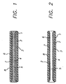
- Figure 1 presents a DVD optical recording element having a single optical recording layer.
- Figure 2 presents a DVD optical recording element having two optical recording layers.
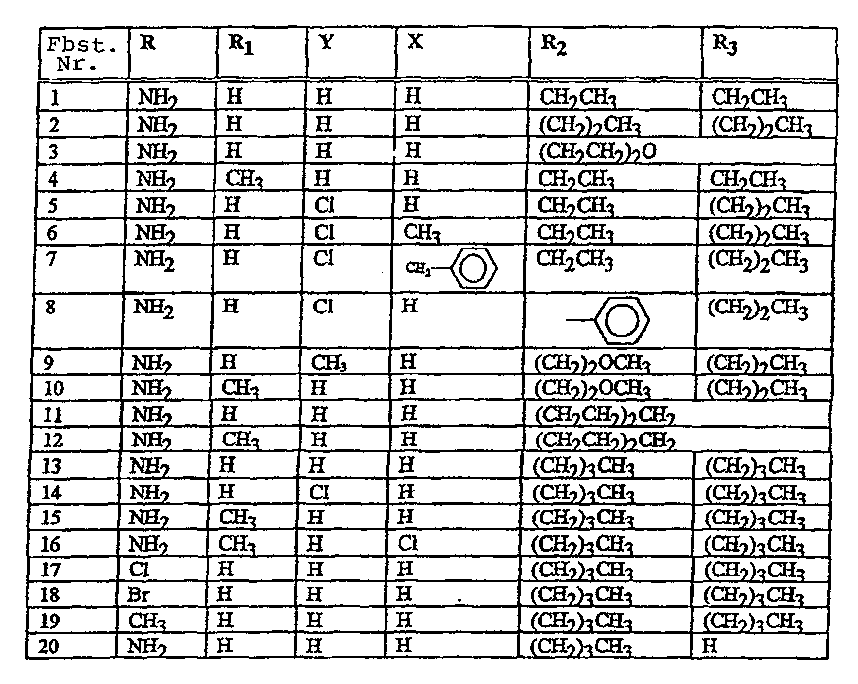
- Novel metallized carbamoylazo dyes included in this invention have the formula (I): wherein;
- Nickel acetate (12.4g) was added to dimethylformamide (280mL) followed by 2-amino-N,N-dipropylbenzamide (22g) and 2-amino-3-hydroxypyridine (11g).
- the compounds can also be made by a two step procedure involving the isolation of the unmetallized dye followed by metallization using nickel acetate in the second step.
- indices of some metallized carbamoylazo dyes of Table 1 are listed in Table 2 below. Indices of the metallized carbamoylazo dyes Azo Dye No. Azo Dye No. Ratio Dyes Index (n/k) at 650 nm 1 2.11/0.094 3 2.20/0.11 2 2.09/0.088 13 2.07/0.084 17 1.90/0.005 18 1.90/0.001 20 2.26/0.131 2 13 1/1 2.07/0.093
- optical elements comprise a light transmitting, typically pregrooved substrate, a dye recording layer overlaying the substrate, a light reflective layer overlaying the light absorptive layer and a protective layer overlaying the light reflective layer.
- the recording process will produce marks of lower reflectivity than the unmarked areas of the disk when written and read with a diode laser emitting between 400 and 660 nm.
- the substituents on the dye molecules are selected such that the real part of the complex refractive index (n) of the unwritten recording layer measured with a light source having a selected wavelength from 400 to 660 nm is greater than 1.8 and the imaginary part (k) is less than 0.2.
- DVD element comprises the following layer arrangement:
- one or more of layers (d), (f) and (g) may be omitted.
- DVD element comprises the following layer arrangement:
- one or both of the protective layers (d) and (f) may be omitted.
- the substrate may be any transparent material that satisfies the mechanical and optical requirements.
- the substrates are generally pregrooved with groove depths from 20 nm to 250 nm, groove widths 0.2 to 1 mm and a pitch 0.5 to 2 mm particularly for CD-R.
- the required groove specifications are mentioned in the description of Figures 1 and 2 above.
- the preferred material is polycarbonate, other materials are glass, polymethylmethacrylate and other suitable polymeric materials.
- the preparation of the optical recording elements of the invention is achieved by spin coating of the dye mixture, with or without addenda, from a suitable solvent onto a transparent substrate.
- the dye mixture, with or without addenda is dissolved in a suitable solvent such that the dye is 20 or less parts by weight to 100 parts of solvent by volume.
- the dye recording layer of the element is then overcoated with a metal reflective layer under reduced pressure by resistive heating or a sputter method and finally overcoated with a protective resin.
- Coating solvents for the dye recording layer are selected to minimize their effect on the substrate.
- Useful solvents include alcohols, hydrocarbon halides, cellosolves, ketones. Examples of solvents are 2,2,3,3-tetrafluoropropanol, tetrachloroethane, dichloromethane, methyl cellosolve, ethyl cellosolve, 1-methoxy-2-propanol, 4-hydroxy-4-methyl-2-pentanone.
- Preferred solvents are alcohols since they have the least effect on the preferred polycarbonate substrates. Mixtures containing these solvents can also be used.
- Useful addenda for the recording layer include stabilizers, surfactants, binders and diluents.
- the reflective layer can be any of the metals conventionally used for optical recording materials.
- Useful metals can be vacuum evaporated or sputtered and include gold, silver, aluminum, copper and alloys thereof.
- the protective layer over the reflective layer is similarly conventional for this art.
- Useful materials include UV curable acrylates.
- An intermediate layer to protect the metal layer from oxidation, can also be present.
- the adhesives can be applied using screen printing, hot roller and spin coating methods.
- the adhesives to form the laminates include UV curable adhesives, hot melt adhesives, UV initiated cationic polymeric adhesives, pressure sensitive adhesives and acrylates.
- the refractive index values for unrecorded recording layers was determined by coating a layer of the dye on a silicon wafer.
- the refractive index values (n and k) were measured by a Variable Angle Spectroscopic Ellipsometer (VASE) manufactured by J. A. Woollan Company.
- a DVD type optical recording element according to Figure 1 was prepared and tested.
- a first assembly was prepared comprising, in the following order, substrate, recording layer, reflective layer and protective layer.
- the second assembly comprised, in the following order, a substrate, a reflecting layer and a protective layer.
- This first assembly was then laminated with an adhesive to the second assembly, protective layer to protective layer.
- the dye for the recording layer was selected from Table 1.
- part by weight of dye 2 was dissolved with ultrasound at room temperature in 1 hour in 50 parts of 2,2,3,3-tetrafluoropropanol by volume. The solution was filtered through a 0.2 ⁇ m filter. The solution was spin coated on the surface of the substrate to an overall optical density of 0.64 at 526 nm. The coating was dried at 60° C for 30 minutes.
- a gold reflective layer was deposited by a sputter process between 19.05 mm and 59.29 mm radii on the dye recording layer to about 40 nm thickness.
- a Uniline 3000 made by First Light Technologies equipped with a Torus 10 DC magnetron source was used for the deposition .
- Ionized argon gas was the gold carrier gas at 6000WS (+/-1000) deposition energy level.
- a protective layer(DaiNippon Daicure SD-220) was spin coated over the gold reflective layer to a thickness of 7 to 11 mm.
- the protective layer was UV cured by the Fusion F300 series cure station with an 'H+' bulb in 2.6 seconds.
- This assembly was prepared as in the first assembly using the substrate, reflective and protective layers.
- the completed DVD element was prepared by laminating the first and second assemblies together through their respective protective layers.
- the laminate was formed by applying Sony SK7000 UV curable adhesive with an Autoroll 560 print head programmed for individual discs.
- the adhesive was silkscreened on to the protective layer of each assembly through a 305 mesh Kodak DOC (durable overcoat) silk-screen with a 90 durometer squeegee used at a 70 degree angle.
- Each assembly was UV cured at a rate of 10.668 meters per minute under a Fusion 450 UV lamp 25.4 cm "H" bulb.
- the two assemblies were mated adhesive to adhesive on a locating spindle and 35.6 N (8 pound force) was applied for 2 minutes.
- the thus formed DVD element was allowed to remain a rest on the spindle for 5 minutes (which resulted in about 90% cure). To be fully cured before testing, the DVD element was left to stand for 24 hours.
- a test system consisting of an optical head with a 635 nm laser, a 0.6 NA lens, push-pull tracking, and 1/2 aperture focusing was used.
- the optics used circularly polarized light to reduce laser feedback effects. Recording and play back were carried out with the same laser at 3.84 m/s rotational speed.
- the read power was kept at 0.5 mW.
- Single frequency marks were recorded with a 1.61 ⁇ m mark length at 10 mW write power thereby forming marks of lower reflectivity than the unmarked area when examined with a light source emitting at 635 nm light.
- a CNR carrier to noise ratio
- Dye 1 was coated on the grooved surface of the substrate to an overall optical density of 0.67 at 526 nm. When written with 8 mW write power a 55 dB CNR was obtained on reading .
- Dye 3 was coated on the grooved surface of the substrate to an overall optical density of 0.62 at 526 nm. When written with 10 mW write power a 55 dB CNR was obtained on reading .
- Dye 13 was coated on the grooved surface of the substrate to an overall optical density of 0.63 at 526 nm. When written with 10 mW write power a 50 dB CNR was obtained on reading
- Dye 20 was coated on the grooved surface of the substrate to an overall optical density of 0.68 at 526 nm. When written with 9 mW write power a 59 dB CNR was obtained on reading.
- the same filter, spin coater, drying conditions, gold deposition process, protective layer application, lamination and testing procedure was used as in the first example.
- a mixture of 1 part dye 2 and 1 part of dye 13 was coated on the grooved surface of the substrate to an overall optical density of 0.46 at 526 nm.
- the coating solvent was a mixture of 77.6 parts of 1-methoxy-2-propanol and 2.4 parts of 4-hydroxy-4-methyl-2-pentanone.
- the substrate had a groove depth of 185 nm and a groove width of 281 nm. When written with 10 mW write power a 57 dB CNR was obtained on reading.
- the selected dyes were spin coated on 5.08 by 5.08 cm (2 by 2 inch) polycarbonate slides.
- Optical density measurements were taken 5 mm from the edge of the slides with a Hewlett Packard 8450A Diode Array Spectrophotometer between 300 nm and 800 nm wave lengths.
- the slide was exposed through the polycarbonate for sixteen days by a method recommended by the Image Stability Technical Center for standard 50 klux Daylight exposure(ANSI IT9.9-1990 " Stability of Color Photographic Images" Section 5 Paragraph 5.6 Describes Simulated Indoor Indirect Daylight exposure). After sixteen days the optical densities were re-measured .
- Table 3 shows the excellent light stability of the recording layers provided by the invention.
- the dyes were spin coated on 5.08 by 5.08 cm (2 by 2 inch) polycarbonate slides.
- Optical density measurements were taken before incubation with a Hewlett Packard 8450A Diode Array Spectrophotometer between 300 nm and 800 nm wave lengths.
- the slides were incubated for six weeks in a Hotpack Temperature Humidity Chamber (Model 434304) set at 80°C temperature and 80% relative humidity with the slides placed, dye side up, in Petri dishes with the tops slightly open. Then optical measurements were taken after six weeks of incubation. To determine the percent optical density loss, from the optical density value at ⁇ -max before incubation the optical density value after incubation was subtracted.
- Table 4 shows the excellent dark stability of the optical recording layers provided by the invention.
Claims (4)
- Metallisierter Carbamoylazo-Farbstoff mit einer Azogruppe, die einen substituierten 3-Hydroxypyridinkern mit einem Phenylkern verbindet,wobei der Phenylkern einen Carbamoyl-Substituenten in ortho-Stellung zur Azogruppe aufweist, mit der Formel(I):worin :

- R
- steht für eine Alkylgruppe mit 1 bis 10 Kohlenstoffatomen,eine Aminogruppe,eine Alkylaminogruppe mit 1 bis 10 Kohlenstoffatomen, eine Dialkylaminogruppe mit 1 bis 10 Kohlenstoffatomen, eine substituierte oder unsubstituierte Benzylaminogruppe, Halogen oder eine Alkoxygruppe mit 1 bis 10 Kohlenstoffatomen ;
- R1
- steht für Wasserstoff oder eine Alkylgruppe mit 1 bis 6 Kohlenstoffatomen ;
- Y
- steht für Wasserstoff, eine Alkylgruppe mit 1 bis 6 Kohlenstoffatomen oder eine Alkoxygruppe mit 1 bis 10 Kohlenstoffatomen oder Halogen ;
- x
- steht für Wasserstoff,eine Alkylgruppe mit 1 bis 10 Kohlenstoffatomen oder eine Alkoxygruppe mit 1 bis 10 Kohlenstoffatomen oder Halogen;
- R2 und R3
- stehen für Wasserstoff,eine Alkylgruppe mit 1 bis 10 Kohlenstoffatomen, eine suustituierte oder unsubstituierte Benzylgruppe,eine Arylgruppe mit 6 bis 10 Kohlenstoffatomen oder eine Heteroarylgruppe mit 5 bis 10 Kohlenstoffatomen;oder R2 und R3 bilden zusammen einen Ring mit 5 bis 10 Kohlenstoffatomen,einen heterocyclischen Ring mit Sauerstoff-,Stickstoff- oder Schwefelatomen mit 4 bis 10 Kohlenstoffatomen.
- Farbstoff nach Anspruch 1, in dem R für eine Aminogruppe steht.
- Farbstoff nach Anspruch 1, ausgewählt aus Tabelle 1 wie folgt :

- Farbstoff nach Anspruch 1, ausgewählt aus den Farbstoffen 1,2,3,13 und 20 von Tabelle 1 gemäss Anspruch 3.
Applications Claiming Priority (2)
| Application Number | Priority Date | Filing Date | Title |
|---|---|---|---|
| US882319 | 1997-06-25 | ||
| US08/882,319 US5821346A (en) | 1997-06-25 | 1997-06-25 | Metallized carbamoylazo dyes |
Publications (2)
| Publication Number | Publication Date |
|---|---|
| EP0887385A1 EP0887385A1 (de) | 1998-12-30 |
| EP0887385B1 true EP0887385B1 (de) | 2002-03-06 |
Family
ID=25380331
Family Applications (1)
| Application Number | Title | Priority Date | Filing Date |
|---|---|---|---|
| EP98201992A Expired - Lifetime EP0887385B1 (de) | 1997-06-25 | 1998-06-15 | Metallisierte Carbamoylazo-farbstoffe |
Country Status (4)
| Country | Link |
|---|---|
| US (1) | US5821346A (de) |
| EP (1) | EP0887385B1 (de) |
| JP (1) | JPH11116834A (de) |
| DE (1) | DE69804057T2 (de) |
Families Citing this family (1)
| Publication number | Priority date | Publication date | Assignee | Title |
|---|---|---|---|---|
| EP1502917A1 (de) * | 2003-07-28 | 2005-02-02 | Clariant International Ltd. | Verwendung von mono- und dikationischen Farbstoffen auf Naphthalin-Imid-Basis in optischen Schichten zur Aufzeichnung von optischen Daten |
Family Cites Families (5)
| Publication number | Priority date | Publication date | Assignee | Title |
|---|---|---|---|---|
| US5272047A (en) * | 1992-06-26 | 1993-12-21 | Eastman Kodak Company | Optical information recording medium using azo dyes |
| US5426015A (en) * | 1993-10-18 | 1995-06-20 | Eastman Kodak Company | Metallized azo dianion with two cationic dye counter ions for optical information recording medium |
| JPH07186547A (ja) * | 1993-10-21 | 1995-07-25 | Eastman Kodak Co | 光学記録層用色素混合物 |
| EP0649880B1 (de) * | 1993-10-21 | 2000-01-12 | Eastman Kodak Company | Metallisierte Azo-ether-farbstoffe für optische Aufzeichnungsschichten |
| DE69522542D1 (de) * | 1994-12-15 | 2001-10-11 | Eastman Kodak Co | Heterocyclische Azoanilinfarbstoffe, Metallkomplexe aus heterocyclischen Azoanilinfarbstoffen und ihre Verwendung in optischen Elementen |
-
1997
- 1997-06-25 US US08/882,319 patent/US5821346A/en not_active Expired - Fee Related
-
1998
- 1998-06-15 DE DE69804057T patent/DE69804057T2/de not_active Expired - Fee Related
- 1998-06-15 EP EP98201992A patent/EP0887385B1/de not_active Expired - Lifetime
- 1998-06-24 JP JP10177075A patent/JPH11116834A/ja active Pending
Also Published As
| Publication number | Publication date |
|---|---|
| US5821346A (en) | 1998-10-13 |
| JPH11116834A (ja) | 1999-04-27 |
| DE69804057D1 (de) | 2002-04-11 |
| DE69804057T2 (de) | 2002-10-31 |
| EP0887385A1 (de) | 1998-12-30 |
Similar Documents
| Publication | Publication Date | Title |
|---|---|---|
| US5294471A (en) | Optical information recording medium using metallized formazan dyes | |
| US5272047A (en) | Optical information recording medium using azo dyes | |
| US5426015A (en) | Metallized azo dianion with two cationic dye counter ions for optical information recording medium | |
| US5536548A (en) | Optical recording disk | |
| US5922504A (en) | Optical recording elements having recording layers containing mixtures of no k metallized formazan and cyanine dyes | |
| EP0887793B1 (de) | Optische Aufzeichnungselemente die metallisierte Carbamoylazofarbstoffen enthalten | |
| JPH1058828A (ja) | 光記録媒体 | |
| EP0837463B1 (de) | Optische Aufzeichnungsschichten, die Mischungen aus metallisierten Formazan-Farbstoffen mit einem K-Wert von Null und symmetrischen und unsymmetrischen Cyanin-Farbstoffen enthalten | |
| EP0937751B1 (de) | Metallisierte Azoether-Farbstoffe und dieselbe enthaltende optische Aufzeichnungsträger | |
| EP0887792B1 (de) | Optische Aufzeichnungselemente die metallisierte Carbamoylazofarbstoffe und Cyaninfarbstoffe enthalten | |
| US6582881B1 (en) | Optical recording elements containing mixture of metallized azo ether and cyanine dyes | |
| US5731054A (en) | Mixtures of low K metallized formazan dyes with symmetrical and unsymmetrical cyanine dyes | |
| US5876821A (en) | Tetra dye mixed with another dye or dyes for optical recording elements | |
| US5348840A (en) | Optical recording medium | |
| EP0887385B1 (de) | Metallisierte Carbamoylazo-farbstoffe | |
| US6447981B1 (en) | Metallized azo thioether dyes | |
| US5922429A (en) | Optical recording elements having recording layers containing mixtures of low k metallized formazan and cyanine dyes | |
| EP0961266A2 (de) | Optisches Aufzeichnungselement, Gemische enthaltend metallisierte Thioether und Cyaninfarbstoffe | |
| US6165683A (en) | Metallized azo-ether dyes for optical recording layers | |
| JP2004181936A (ja) | 光記録媒体 | |
| JP3398495B2 (ja) | 光記録媒体 | |
| JPH08310121A (ja) | 光記録媒体 |
Legal Events
| Date | Code | Title | Description |
|---|---|---|---|
| PUAI | Public reference made under article 153(3) epc to a published international application that has entered the european phase |
Free format text: ORIGINAL CODE: 0009012 |
|
| AK | Designated contracting states |
Kind code of ref document: A1 Designated state(s): DE FR GB IE |
|
| AX | Request for extension of the european patent |
Free format text: AL;LT;LV;MK;RO;SI |
|
| 17P | Request for examination filed |
Effective date: 19990605 |
|
| AKX | Designation fees paid |
Free format text: DE FR GB IE |
|
| 17Q | First examination report despatched |
Effective date: 20000614 |
|
| GRAG | Despatch of communication of intention to grant |
Free format text: ORIGINAL CODE: EPIDOS AGRA |
|
| GRAG | Despatch of communication of intention to grant |
Free format text: ORIGINAL CODE: EPIDOS AGRA |
|
| GRAH | Despatch of communication of intention to grant a patent |
Free format text: ORIGINAL CODE: EPIDOS IGRA |
|
| GRAH | Despatch of communication of intention to grant a patent |
Free format text: ORIGINAL CODE: EPIDOS IGRA |
|
| REG | Reference to a national code |
Ref country code: GB Ref legal event code: IF02 |
|
| GRAA | (expected) grant |
Free format text: ORIGINAL CODE: 0009210 |
|
| AK | Designated contracting states |
Kind code of ref document: B1 Designated state(s): DE FR GB IE |
|
| REF | Corresponds to: |
Ref document number: 69804057 Country of ref document: DE Date of ref document: 20020411 |
|
| ET | Fr: translation filed | ||
| PLBE | No opposition filed within time limit |
Free format text: ORIGINAL CODE: 0009261 |
|
| STAA | Information on the status of an ep patent application or granted ep patent |
Free format text: STATUS: NO OPPOSITION FILED WITHIN TIME LIMIT |
|
| 26N | No opposition filed |
Effective date: 20021209 |
|
| PGFP | Annual fee paid to national office [announced via postgrant information from national office to epo] |
Ref country code: IE Payment date: 20050414 Year of fee payment: 8 |
|
| PGFP | Annual fee paid to national office [announced via postgrant information from national office to epo] |
Ref country code: GB Payment date: 20050506 Year of fee payment: 8 |
|
| PGFP | Annual fee paid to national office [announced via postgrant information from national office to epo] |
Ref country code: FR Payment date: 20050602 Year of fee payment: 8 |
|
| PGFP | Annual fee paid to national office [announced via postgrant information from national office to epo] |
Ref country code: DE Payment date: 20050630 Year of fee payment: 8 |
|
| PG25 | Lapsed in a contracting state [announced via postgrant information from national office to epo] |
Ref country code: IE Free format text: LAPSE BECAUSE OF NON-PAYMENT OF DUE FEES Effective date: 20060615 Ref country code: GB Free format text: LAPSE BECAUSE OF NON-PAYMENT OF DUE FEES Effective date: 20060615 |
|
| PG25 | Lapsed in a contracting state [announced via postgrant information from national office to epo] |
Ref country code: DE Free format text: LAPSE BECAUSE OF NON-PAYMENT OF DUE FEES Effective date: 20070103 |
|
| GBPC | Gb: european patent ceased through non-payment of renewal fee |
Effective date: 20060615 |
|
| REG | Reference to a national code |
Ref country code: IE Ref legal event code: MM4A |
|
| REG | Reference to a national code |
Ref country code: FR Ref legal event code: ST Effective date: 20070228 |
|
| PG25 | Lapsed in a contracting state [announced via postgrant information from national office to epo] |
Ref country code: FR Free format text: LAPSE BECAUSE OF NON-PAYMENT OF DUE FEES Effective date: 20060630 |