EP0886076A2 - Actionneur pour un frein a disque pour vehicules actionne electriquement - Google Patents
Actionneur pour un frein a disque pour vehicules actionne electriquement Download PDFInfo
- Publication number
- EP0886076A2 EP0886076A2 EP98110259A EP98110259A EP0886076A2 EP 0886076 A2 EP0886076 A2 EP 0886076A2 EP 98110259 A EP98110259 A EP 98110259A EP 98110259 A EP98110259 A EP 98110259A EP 0886076 A2 EP0886076 A2 EP 0886076A2
- Authority
- EP
- European Patent Office
- Prior art keywords
- spindle
- rolling
- electric motor
- roller
- spindle nut
- Prior art date
- Legal status (The legal status is an assumption and is not a legal conclusion. Google has not performed a legal analysis and makes no representation as to the accuracy of the status listed.)
- Withdrawn
Links
- 238000005096 rolling process Methods 0.000 claims description 64
- 238000006073 displacement reaction Methods 0.000 claims description 4
- 230000003134 recirculating effect Effects 0.000 claims 1
- 230000033001 locomotion Effects 0.000 abstract description 17
- 230000005540 biological transmission Effects 0.000 description 10
- 238000012986 modification Methods 0.000 description 3
- 238000012546 transfer Methods 0.000 description 3
- 238000011144 upstream manufacturing Methods 0.000 description 3
- 230000001133 acceleration Effects 0.000 description 2
- 238000013461 design Methods 0.000 description 2
- 230000004048 modification Effects 0.000 description 2
- 238000013519 translation Methods 0.000 description 2
- 230000001154 acute effect Effects 0.000 description 1
- 238000013459 approach Methods 0.000 description 1
- 230000009286 beneficial effect Effects 0.000 description 1
- 230000033228 biological regulation Effects 0.000 description 1
- 238000005352 clarification Methods 0.000 description 1
- 230000000295 complement effect Effects 0.000 description 1
- 238000010276 construction Methods 0.000 description 1
- 238000011161 development Methods 0.000 description 1
- 230000018109 developmental process Effects 0.000 description 1
- 238000010586 diagram Methods 0.000 description 1
- 230000000694 effects Effects 0.000 description 1
- 238000005516 engineering process Methods 0.000 description 1
- 238000011156 evaluation Methods 0.000 description 1
- 239000007787 solid Substances 0.000 description 1
Images


Classifications
-
- F—MECHANICAL ENGINEERING; LIGHTING; HEATING; WEAPONS; BLASTING
- F16—ENGINEERING ELEMENTS AND UNITS; GENERAL MEASURES FOR PRODUCING AND MAINTAINING EFFECTIVE FUNCTIONING OF MACHINES OR INSTALLATIONS; THERMAL INSULATION IN GENERAL
- F16H—GEARING
- F16H25/00—Gearings comprising primarily only cams, cam-followers and screw-and-nut mechanisms
- F16H25/18—Gearings comprising primarily only cams, cam-followers and screw-and-nut mechanisms for conveying or interconverting oscillating or reciprocating motions
- F16H25/20—Screw mechanisms
- F16H25/22—Screw mechanisms with balls, rollers, or similar members between the co-operating parts; Elements essential to the use of such members
- F16H25/2247—Screw mechanisms with balls, rollers, or similar members between the co-operating parts; Elements essential to the use of such members with rollers
- F16H25/2252—Planetary rollers between nut and screw
-
- B—PERFORMING OPERATIONS; TRANSPORTING
- B60—VEHICLES IN GENERAL
- B60T—VEHICLE BRAKE CONTROL SYSTEMS OR PARTS THEREOF; BRAKE CONTROL SYSTEMS OR PARTS THEREOF, IN GENERAL; ARRANGEMENT OF BRAKING ELEMENTS ON VEHICLES IN GENERAL; PORTABLE DEVICES FOR PREVENTING UNWANTED MOVEMENT OF VEHICLES; VEHICLE MODIFICATIONS TO FACILITATE COOLING OF BRAKES
- B60T1/00—Arrangements of braking elements, i.e. of those parts where braking effect occurs specially for vehicles
- B60T1/02—Arrangements of braking elements, i.e. of those parts where braking effect occurs specially for vehicles acting by retarding wheels
- B60T1/06—Arrangements of braking elements, i.e. of those parts where braking effect occurs specially for vehicles acting by retarding wheels acting otherwise than on tread, e.g. employing rim, drum, disc, or transmission or on double wheels
- B60T1/065—Arrangements of braking elements, i.e. of those parts where braking effect occurs specially for vehicles acting by retarding wheels acting otherwise than on tread, e.g. employing rim, drum, disc, or transmission or on double wheels employing disc
-
- B—PERFORMING OPERATIONS; TRANSPORTING
- B60—VEHICLES IN GENERAL
- B60T—VEHICLE BRAKE CONTROL SYSTEMS OR PARTS THEREOF; BRAKE CONTROL SYSTEMS OR PARTS THEREOF, IN GENERAL; ARRANGEMENT OF BRAKING ELEMENTS ON VEHICLES IN GENERAL; PORTABLE DEVICES FOR PREVENTING UNWANTED MOVEMENT OF VEHICLES; VEHICLE MODIFICATIONS TO FACILITATE COOLING OF BRAKES
- B60T13/00—Transmitting braking action from initiating means to ultimate brake actuator with power assistance or drive; Brake systems incorporating such transmitting means, e.g. air-pressure brake systems
- B60T13/74—Transmitting braking action from initiating means to ultimate brake actuator with power assistance or drive; Brake systems incorporating such transmitting means, e.g. air-pressure brake systems with electrical assistance or drive
- B60T13/741—Transmitting braking action from initiating means to ultimate brake actuator with power assistance or drive; Brake systems incorporating such transmitting means, e.g. air-pressure brake systems with electrical assistance or drive acting on an ultimate actuator
-
- F—MECHANICAL ENGINEERING; LIGHTING; HEATING; WEAPONS; BLASTING
- F16—ENGINEERING ELEMENTS AND UNITS; GENERAL MEASURES FOR PRODUCING AND MAINTAINING EFFECTIVE FUNCTIONING OF MACHINES OR INSTALLATIONS; THERMAL INSULATION IN GENERAL
- F16D—COUPLINGS FOR TRANSMITTING ROTATION; CLUTCHES; BRAKES
- F16D65/00—Parts or details
- F16D65/14—Actuating mechanisms for brakes; Means for initiating operation at a predetermined position
- F16D65/16—Actuating mechanisms for brakes; Means for initiating operation at a predetermined position arranged in or on the brake
- F16D65/18—Actuating mechanisms for brakes; Means for initiating operation at a predetermined position arranged in or on the brake adapted for drawing members together, e.g. for disc brakes
-
- F—MECHANICAL ENGINEERING; LIGHTING; HEATING; WEAPONS; BLASTING
- F16—ENGINEERING ELEMENTS AND UNITS; GENERAL MEASURES FOR PRODUCING AND MAINTAINING EFFECTIVE FUNCTIONING OF MACHINES OR INSTALLATIONS; THERMAL INSULATION IN GENERAL
- F16D—COUPLINGS FOR TRANSMITTING ROTATION; CLUTCHES; BRAKES
- F16D2121/00—Type of actuator operation force
- F16D2121/18—Electric or magnetic
- F16D2121/24—Electric or magnetic using motors
-
- F—MECHANICAL ENGINEERING; LIGHTING; HEATING; WEAPONS; BLASTING
- F16—ENGINEERING ELEMENTS AND UNITS; GENERAL MEASURES FOR PRODUCING AND MAINTAINING EFFECTIVE FUNCTIONING OF MACHINES OR INSTALLATIONS; THERMAL INSULATION IN GENERAL
- F16D—COUPLINGS FOR TRANSMITTING ROTATION; CLUTCHES; BRAKES
- F16D2125/00—Components of actuators
- F16D2125/18—Mechanical mechanisms
- F16D2125/20—Mechanical mechanisms converting rotation to linear movement or vice versa
- F16D2125/34—Mechanical mechanisms converting rotation to linear movement or vice versa acting in the direction of the axis of rotation
- F16D2125/40—Screw-and-nut
- F16D2125/405—Screw-and-nut with differential thread
Definitions
- the invention relates to a drive for an electrically operated Vehicle brake according to the preamble of one of the claims 1, 8 or 9.
- DE 195 43 098 C2 describes an electrically actuated vehicle brake described.
- electrically actuated vehicle brake designed as a disc brake, whose brake shoes using an electrical Drive electric motor can be pressed onto the brake disc are.
- the electric motor is in the direction of displacement of the friction elements arranged spindle gear in the form a planetary roller screw known from DE 37 39 059 with an axially displaceable acting on the brake shoe mounted piston connected.
- This well-known planetary roller thread spindle has low Coefficients of friction and allows a relatively high Power transmission, so that in general for the actuation of Vehicle brakes require power in just one gear stage can be reached. Because of their functional principle disadvantageous in this spindle gear that the transmission the tangential forces from spindle rod to rolling or Roll body and slippage from these on the spindle nut is. Thus, the well-known planetary roller screw has a slope that is not precisely defined and consequently also no slope constant power transmission.
- a spindle drive as a direct drive, i.e. without an additional in between switched gear stage, or a spindle drive with an upstream gearbox lower Translation required either to apply a brake Forces with a precisely defined slope or special high forces to apply a brake with a less exact Slope are generated.
- a compact electric motor is used to operate the brake, which is light in weight and small in volume and thus be provided directly on the wheel brake can.
- the runner of the motor with the spindle nut of the SPWG spindle rotatably connected.
- the spindle rod is secured against rotation and in turn directly with the brake actuating piston connected, which the friction lining against the brake disc presses.
- the electric motor is non-rotatable with the spindle rod of the SPWG spindle connected, the spindle nut on the brake piston works.
- the inner diameter of the rotor of the electric motor is dimensioned that the spindle rod be accommodated in the rotor can and thus an adjustment movement is possible.
- the inside diameter of the rotor of the electric motor dimensioned so that it receives the spindle nut of an SPWG spindle can, which is rotatably connected to the rotor.
- the spindle rod then acts on the Brake piston.
- the overall length is also in this embodiment of the brake actuator reduced.
- the rotor of the electric motor is rotatably connected to a gear be, the output shaft in turn the spindle rod the SPWG spindle is. Also acts in this embodiment then their spindle nut on the brake piston, making a total the efficiency of the brake actuator can be increased.
- the drive according to the invention thus has a particularly compact design and lightweight construction and in particular has a solid Transfer ratio.
- the invention Drive from only a few components and leaves in advantageously equipped with any necessary Sensors too.
- the invention has Drive due to the low friction losses that occur in it high efficiency.
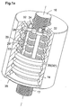
- the SPWG spindle 12 has in the embodiment of Fig.1a in contrast to motion screws known per se from one Spindle rod 16 on that with a single or multi-course Fine thread and a number of cylindrical Rolling body 28 is surrounded.
- the rolling bodies 28 are in any Number and at even or uneven intervals arranged like a planet.
- SPWG spindle 12 are, for example, eight rolling elements 28 intended.
- the rolling or rolling elements 28 have one Fine thread 17 of the spindle rod 16 corresponding groove profiling on.
- a force introduced into the spindle rod 16 is from the single or multi-thread spindle rod fine thread 17 on sections trained groove profiles 29 the number of rolling or Transfer rolling elements 28.
- the force is applied by means of sliding contact a number of guide rings 30 or a guide body 30 ' transmitted with annular circumferential guide grilles 31 '.
- the Guide rings 30 and the guide body 30 ' are in the Spindle nut 14 supported by ball or roller bearing rings, so that between the guide rings 30 and the guide body 30 'and the spindle nut 14 no occurring in the circumferential direction Forces or torques can be transmitted.
- ball or roller bearings 32 are provided for contact storage of the rolling or rolling elements 28 and around Distance between the rolling or rolling elements 28 to each other constant hold.
- the ball or Roller bearings 32 are direct via pins 33 and bushes 34 held in the spindle nut 14 and the ball or roller bearings 32 opposite ball or roller bearings 32 ' are held in the spindle cover 35 via pins and bushings.
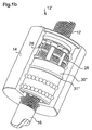
- FIG. 1b shows a modification of the one shown in FIG. partially cut pitch-true planetary roller thread (SPWG) spindle 12 'shown, in which in Difference from the embodiment in Fig.1a in a guide body 30 '' a helical guide groove 31 '' is formed.
- SPWG pitch-true planetary roller thread
- the SPWG spindle 12 ' is the axial movement between the spindle nut 14 'and the guide body 30 '', in which the spiral-shaped guide groove 31 '' is quite desirable.
- the Axial movement between the spindle nut 14 'and the guide body 30 '' is the same or opposite, is with one co-rotating movement of spindle nut 14 'and guide body 30 '' the slopes of the two elements 14 ' and 30 '' summing gear and thus a gear with a get relatively high slope while at a opposite rotational movement between the spindle nut 14 ' and the guide body 30 ′′ the slopes from each other subtracting gear with a corresponding low Slope is created.
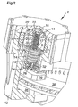
- FIG. 2 a whole of 2, partially cut brake actuator 2 shown, wherein in 2 an electric motor 4 and in the lower part a brake pad in the form of a friction pad 36 is reproduced are.
- the electric motor 4 has a rotor 6 and a stand 8 and in between an air gap 10.
- the electric motor 4 stands above the pitch-true planetary roller thread (SPWG) spindle 12 with one attached to a brake piston 24 Brake pad 36 in operative connection.
- SPWG pitch-true planetary roller thread
- the spindle nut in the embodiment in Figure 2 14 via a spindle cover firmly connected to it 35 driven and not the spindle rod 16.
- the spindle cover 35 is in turn rotationally fixed to the rotor 6 of the motor 4 connected.
- the axis of the spindle cover 35 is shown in FIG Embodiment simultaneously the axis of the electric motor 4.
- the spindle nut 14 and thus also the rotor 6 of the electric motor are at their motor end supported a bearing 18, which in Figure 2 as an angular contact ball bearing is trained.
- the rotatable with the rotor 6 connected cover 35 is fixed with a counter flange 40 connected.
- the counter flange 40 is in turn by means of a radial bearing 20 and an axial bearing (thrust bearing) 22 are supported, which in the preferred embodiment of FIG is designed as an axial roller bearing.
- the support is required since the entire, over the spindle cover 35 transmitted axial forces must be supported.
- the brake actuator 2 with the embodiment shown in Fig.2 works as follows: the electric motor 4 drives the spindle nut 14 via the spindle cover 35. As a result, the rotationally fixed spindle rod 16 together with the on the brake piston 24 fastened brake lining and against the brake disc 38 is pressed or it is made from this pulled back.
- the wear occurring on the brake pad 36 can be adjusted of the brake piston 24 with the friction lining attached to it 36 compared to the spindle nut 14 by a in Fig.2 indicated by an arrow with tips on both sides Adjustment path 26 can be adjusted; the adjustment path 26 is in the order of magnitude in the embodiment of FIG of about 37mm.
- the stroke of the brake piston 24 and thus the The brake lining 36 attached to the brake piston can vary depending on the thickness the actuation and stiffness of the brake caliper 42 in the embodiment of Figure 2 be up to 2mm.
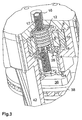
- the first alternative embodiment shown in FIG of the drive according to the invention for a brake actuator 2 has one connected to a brake lining (friction lining) 36 Electric motor 4.
- the electric motor 4 which has a rotor 6 and has a stand 8 and an air gap 10 therebetween, is also above a pitch-true planetary roller thread (SPWG) spindle 12 with the brake pad 36 in operative connection.
- SPWG pitch-true planetary roller thread
- the spindle nut 14 also arranged within the rotor 6 and rotatably with it connected. Also in the first alternative embodiment is again the spindle nut 14 driven and not the Spindle rod 16. The axis of the spindle nut 14 is here at the same time the axis of the electric motor 4.
- the spindle nut 14 and thus also the rotor 6 of the electric motor 4 are at their brake pad side end by means of a Radial bearing 18, which is an angular contact ball bearing, and on her opposite end by means of another radial bearing 20 supported, which is also an angular contact ball bearing (The axial forces can, however, also have an additional Axial bearings are supported as in Fig. 2). This support is required as the whole, over the spindle nut 14 transmitted axial forces must be supported.
- a drive of the brake actuator 2 corresponds to the mode of operation of the drive described with reference to Figures 2 and 2 Brake actuator.
- the wear of the brake lining 36 can also be adjusted by about 37mm and also the stroke of the brake piston 24 can, depending on the strength or
- the actuation and rigidity of the brake caliper 42 are up to 2 mm.
- the SPWG spindle 12 is carried out exactly as on the basis 2 and 2 is described. Likewise, one in the Spindle rod 16 initiated force from the single or multi-course Spindle rod fine thread 17 on sections trained groove profiles 29 of a plurality of rolling or rolling elements 28 transferred.
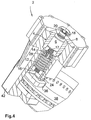
- the second alternative embodiment shown in Figure 4 distinguishes the drive of the brake actuator 2 according to the invention differs from the first alternative described with reference to FIG Embodiment in that in the second alternative Embodiment for the sake of reducing the rotationally moved masses the spindle rod 16 within of the rotor 6 arranged and rotatably connected to this is. Therefore, in the second alternative embodiment the spindle rod 16 and not the spindle nut 14 driven.
- the axis is in the second alternative embodiment the spindle rod 16 simultaneously the axis of the electric motor 4.
- the spindle nut 14 in the first alternative embodiment is in the second alternative embodiment the spindle rod 16 and thus also the rotor 6 of the electric motor at one end by means of a radial bearing 18, for example in the form of a ball bearing, and by means of a Thrust bearing 20 supported, for example a tapered roller bearing is. This support is also required since all transmitted over the mirror rod 16 Axial forces must be supported.
- the operation of the brake actuator 2 with the drive according to The second alternative embodiment is as follows: The This time, electric motor 4 drives the spindle rod 16, as a result the non-rotatable spindle nut 14 and that on the brake piston 24 attached brake pad 36 propelled and against the brake disc 38 pressed or returned from this.
- the wear of the brake pad 36 occurs Readjust the brake piston 24 with the attached Friction lining 36 with respect to the spindle rod 16 also one in the order of approximately 37 mm adjusted.
- the SPWG spindle 12 is constructed in the same way as in the above
- the embodiments described are also those in the Spindle rod 16 applied force in the same way sectionally formed groove profiles of several rolling or Transfer rolling elements 28.
- the guide rings 30 or the guide body 30 'are mounted in an analogous manner can also no forces occurring in the circumferential direction or torques are transmitted.
- Fine thread 17 of the spindle rod 16 and the guide grooves 29 'of the rolling or rolling elements 28 no slip occurs and Inclination errors due to slip are also excluded.
- the structure the SPWG spindle 12 and its mode of operation are exactly the same as above using the first alternative embodiment is set out in detail.
- FIG. 6 is also like the one described with reference to FIG. second alternative embodiment for reasons the reduction of the rotor-moving masses the spindle rod 16 arranged within the rotor 6 and with this non-rotatably connected. Also in the fourth alternative embodiment becomes the spindle rod 16 and not the spindle nut 14 driven.
- the axis of the spindle rod 16 is also again at the same time the axis of the electric motor 4.
- the spindle rod 16 and thus also the rotor of the electric motor 4 are between the spindle 12 and the electric motor 4 with a radial bearing 18, for example in the form of a ball bearing and supported with an axial bearing 20, which is also in the fourth alternative embodiment is a ball roller bearing.
- the support is also necessary again, as the whole supported on the spindle rod 16 transmitted axial forces Need to become.
- Fig. 7 are in a three-dimensional graphic on the of The zero point in Fig. 7 diagonally to the left axis Pitch in mm per revolution on that from the zero point in Fig. 7 outgoing diagonally to the right and perpendicular to the slope axis axial axis the axial force in kN and on the in Fig. 7 vertical axis of efficiency plotted.
- a Pitch of 2.5mm per revolution an efficiency of about 0.96 reached.
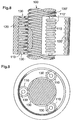
- a spindle rod 100 has three threads with an acute angle of 90 °.
- Three rolling or rolling elements 110 have annular teeth 110 'over their entire length.
- the annular teeth 110 'of the rolling or rolling elements 110 have the same axial pitch as the thread 100 'of the spindle rod 100, and the shape of the teeth 110 'of the rolling or Rolling element 110 corresponds to the shape of the threads 100 '.
- a cylindrical spindle nut 120 points in a bore a plurality of inner annular grooves 120 ', which over the entire length of the spindle nut 120 are arranged.
- the ring grooves 120 'of the spindle nut 120 have the same axial Division like the annular teeth 110 of the rolling or rolling elements 110 and a shape that matches that of the annular Teeth 110 'of the rolling or rolling elements 110 complementary is.
- the spindle nut 120 has the same number of ring grooves 120 'as the number of teeth 110' of each rolling or rolling element 110.
- each rolling or rolling element has a short one at each end Has pivot 130, these are for the operation of Screw drive not absolutely necessary and they are only provided to the rollers 110 in the in Fig.9 to bring reproduced position during assembly.
- the in Fig. 8 and 9 shown screw drive is in very applicable in many cases in which a rotational movement into a linear or axial movement is to be converted and vice versa.
- Embodiment in which the SPWG spindle is used may for reasons of efficiency improvement Rotary motion of an electric motor even when using the DE 27 18 888 C2 known spindle drive through an effect the gear 9 in Figure 5 corresponding gear in a Rotational movement of low speed can be reduced. Also in in this case, analogous to the embodiment according to FIG Spindle rod 100 driven by the gear. Here is then also the axis of the drive shaft of the gearbox at the same time the axis of the electric motor. Otherwise apply same considerations as to how it works the third embodiment shown in Figure 5 are.
Applications Claiming Priority (4)
| Application Number | Priority Date | Filing Date | Title |
|---|---|---|---|
| DE19725372 | 1997-06-16 | ||
| DE19725372 | 1997-06-16 | ||
| DE19807432 | 1998-02-23 | ||
| DE19807432A DE19807432A1 (de) | 1997-06-16 | 1998-02-23 | Antrieb für eine elektrisch betätigbare Fahrzeugbremse |
Publications (2)
| Publication Number | Publication Date |
|---|---|
| EP0886076A2 true EP0886076A2 (fr) | 1998-12-23 |
| EP0886076A3 EP0886076A3 (fr) | 1999-12-15 |
Family
ID=26037460
Family Applications (1)
| Application Number | Title | Priority Date | Filing Date |
|---|---|---|---|
| EP98110259A Withdrawn EP0886076A3 (fr) | 1997-06-16 | 1998-06-05 | Actionneur pour un frein a disque pour vehicules actionne electriquement |
Country Status (1)
| Country | Link |
|---|---|
| EP (1) | EP0886076A3 (fr) |
Cited By (8)
| Publication number | Priority date | Publication date | Assignee | Title |
|---|---|---|---|---|
| WO2001040673A1 (fr) * | 1999-12-02 | 2001-06-07 | Haldex Brake Products Ab | Frein a disque |
| WO2001040672A1 (fr) * | 1999-12-02 | 2001-06-07 | Haldex Brake Products Ab | Frein a disque |
| US7066304B2 (en) | 1999-12-02 | 2006-06-27 | Haldex Brake Products Ab | Disc brake |
| WO2013156391A1 (fr) * | 2012-04-20 | 2013-10-24 | Ipgate Ag | Système de paliers dans un entraînement axial |
| KR20190008268A (ko) * | 2016-05-19 | 2019-01-23 | 할덱스 브레이크 프로덕츠 아베 | 브레이크 서브조립체와 브레이크 조립체 그룹 |
| CN109807782A (zh) * | 2019-03-10 | 2019-05-28 | 西北工业大学 | 一种用于多型号的行星滚柱丝杠副装配夹具 |
| CN112855887A (zh) * | 2021-03-19 | 2021-05-28 | 易通共享技术(广州)有限公司 | 一种车辆电子制动变拉力驱动器 |
| CN115111294A (zh) * | 2022-08-25 | 2022-09-27 | 杭州新剑机电传动股份有限公司 | 适用于线控制动系统的汽车用机电作动器 |
Citations (5)
| Publication number | Priority date | Publication date | Assignee | Title |
|---|---|---|---|---|
| DE2718888A1 (de) * | 1976-05-03 | 1977-11-17 | Illinois Tool Works | Vorrichtung zum umwandeln einer drehbewegung in eine lineare bewegung |
| US4995483A (en) * | 1989-12-18 | 1991-02-26 | Aircraft Braking Systems Corporation | Motor position feedback controlled electrically actuated aircraft brake |
| US5370012A (en) * | 1993-03-08 | 1994-12-06 | Stanley; Richard B. | Linear actuation roller bearing nut |
| DE19543098A1 (de) * | 1995-05-19 | 1996-12-12 | Continental Ag | Bremsaktor für elektrisch betätigbare Fahrzeugbremse |
| DE19540634C1 (de) * | 1995-10-31 | 1997-03-13 | Deutsche Forsch Luft Raumfahrt | Vorrichtung zur Umwandlung einer Dreh- in eine Axialbewegung |
-
1998
- 1998-06-05 EP EP98110259A patent/EP0886076A3/fr not_active Withdrawn
Patent Citations (5)
| Publication number | Priority date | Publication date | Assignee | Title |
|---|---|---|---|---|
| DE2718888A1 (de) * | 1976-05-03 | 1977-11-17 | Illinois Tool Works | Vorrichtung zum umwandeln einer drehbewegung in eine lineare bewegung |
| US4995483A (en) * | 1989-12-18 | 1991-02-26 | Aircraft Braking Systems Corporation | Motor position feedback controlled electrically actuated aircraft brake |
| US5370012A (en) * | 1993-03-08 | 1994-12-06 | Stanley; Richard B. | Linear actuation roller bearing nut |
| DE19543098A1 (de) * | 1995-05-19 | 1996-12-12 | Continental Ag | Bremsaktor für elektrisch betätigbare Fahrzeugbremse |
| DE19540634C1 (de) * | 1995-10-31 | 1997-03-13 | Deutsche Forsch Luft Raumfahrt | Vorrichtung zur Umwandlung einer Dreh- in eine Axialbewegung |
Cited By (12)
| Publication number | Priority date | Publication date | Assignee | Title |
|---|---|---|---|---|
| WO2001040673A1 (fr) * | 1999-12-02 | 2001-06-07 | Haldex Brake Products Ab | Frein a disque |
| WO2001040672A1 (fr) * | 1999-12-02 | 2001-06-07 | Haldex Brake Products Ab | Frein a disque |
| US7066304B2 (en) | 1999-12-02 | 2006-06-27 | Haldex Brake Products Ab | Disc brake |
| WO2013156391A1 (fr) * | 2012-04-20 | 2013-10-24 | Ipgate Ag | Système de paliers dans un entraînement axial |
| KR20150005989A (ko) * | 2012-04-20 | 2015-01-15 | 이페게이트 아게 | 축방향 구동부의 베어링 배열 |
| US10250098B2 (en) | 2012-04-20 | 2019-04-02 | Ipgate Ag | Bearing arrangement in an axial drive with dual stators and one rotor |
| KR102020530B1 (ko) | 2012-04-20 | 2019-09-10 | 이페게이트 아게 | 축방향 구동부의 베어링 배열 |
| KR20190008268A (ko) * | 2016-05-19 | 2019-01-23 | 할덱스 브레이크 프로덕츠 아베 | 브레이크 서브조립체와 브레이크 조립체 그룹 |
| CN109807782A (zh) * | 2019-03-10 | 2019-05-28 | 西北工业大学 | 一种用于多型号的行星滚柱丝杠副装配夹具 |
| CN112855887A (zh) * | 2021-03-19 | 2021-05-28 | 易通共享技术(广州)有限公司 | 一种车辆电子制动变拉力驱动器 |
| CN112855887B (zh) * | 2021-03-19 | 2022-03-29 | 易通共享技术(广州)有限公司 | 一种车辆电子制动变拉力驱动器 |
| CN115111294A (zh) * | 2022-08-25 | 2022-09-27 | 杭州新剑机电传动股份有限公司 | 适用于线控制动系统的汽车用机电作动器 |
Also Published As
| Publication number | Publication date |
|---|---|
| EP0886076A3 (fr) | 1999-12-15 |
Similar Documents
| Publication | Publication Date | Title |
|---|---|---|
| EP0743470B1 (fr) | Moteur de frein pour frein à actionnement électrique de véhicule | |
| DE10112570B4 (de) | Elektrisch betätigbare Scheibenbremse | |
| DE3808989C2 (fr) | ||
| DE19807432A1 (de) | Antrieb für eine elektrisch betätigbare Fahrzeugbremse | |
| DE19543098C2 (de) | Bremsaktor für elektrisch betätigbare Fahrzeugbremse | |
| EP0916568A2 (fr) | Actionneur pour engendrer un angle de braquage supplémentaire pour véhicules automobiles | |
| EP1098423A1 (fr) | Entraínement pour meubles par moteur électrique | |
| DE3815225A1 (de) | Sperrbares ausgleichsgetriebe | |
| DE19605988A1 (de) | Vorrichtung zum Betätigen einer Radbremse eines Fahrzeuges | |
| DE69819826T2 (de) | Servosteuersystem | |
| EP0886076A2 (fr) | Actionneur pour un frein a disque pour vehicules actionne electriquement | |
| DE4243267A1 (de) | Lenkgetriebe | |
| DE19736734C2 (de) | Lineares Stellglied und bevorzugte Anwendung | |
| DD201936A5 (de) | Vorrichtung zur umwandlung einer drehenden bewegung in eine lineare bewegung | |
| EP3208164A1 (fr) | Vis d'entrainement a bille | |
| EP0066122B1 (fr) | Transmission différentielle | |
| DE19519310A1 (de) | Differentialgetriebe für einen elektromotorisch betriebenen Bremsaktor | |
| DE3909910A1 (de) | Hydraulische drehbetaetigungsvorrichtung | |
| EP3807143B1 (fr) | Direction assistée par câble avec entraînement par broche | |
| EP0581069A1 (fr) | Unité d'entraînement pour rouleaux | |
| EP0870129B2 (fr) | Dispositif pour transformer un mouvement rotatif en un mouvement axial | |
| DE19719510A1 (de) | Vorrichtung zur Umwandlung einer Drehbewegung in eine geradlinige Bewegung | |
| WO2006058743A1 (fr) | Transmission | |
| EP1831590B1 (fr) | Dispositif, notamment engrenage planetaire, comprenant un corps de base en anneau | |
| DE602005006042T2 (de) | Vorrichtung zur Umwandlung einer rotierenden Bewegung in eine lineare Bewegung. |
Legal Events
| Date | Code | Title | Description |
|---|---|---|---|
| PUAI | Public reference made under article 153(3) epc to a published international application that has entered the european phase |
Free format text: ORIGINAL CODE: 0009012 |
|
| AK | Designated contracting states |
Kind code of ref document: A2 Designated state(s): DE FR IT SE |
|
| AX | Request for extension of the european patent |
Free format text: AL;LT;LV;MK;RO;SI |
|
| PUAL | Search report despatched |
Free format text: ORIGINAL CODE: 0009013 |
|
| AK | Designated contracting states |
Kind code of ref document: A3 Designated state(s): AT BE CH CY DE DK ES FI FR GB GR IE IT LI LU MC NL PT SE |
|
| AX | Request for extension of the european patent |
Free format text: AL;LT;LV;MK;RO;SI |
|
| AKX | Designation fees paid | ||
| RBV | Designated contracting states (corrected) |
Designated state(s): DE FR IT SE |
|
| REG | Reference to a national code |
Ref country code: DE Ref legal event code: 8566 |
|
| 17P | Request for examination filed |
Effective date: 20000724 |
|
| 17Q | First examination report despatched |
Effective date: 20020419 |
|
| STAA | Information on the status of an ep patent application or granted ep patent |
Free format text: STATUS: THE APPLICATION HAS BEEN WITHDRAWN |
|
| 18W | Application withdrawn |
Withdrawal date: 20020824 |