EP0886055B1 - Method and apparatus for controlling a spark ignited internal combustion engine - Google Patents
Method and apparatus for controlling a spark ignited internal combustion engine Download PDFInfo
- Publication number
- EP0886055B1 EP0886055B1 EP19980401507 EP98401507A EP0886055B1 EP 0886055 B1 EP0886055 B1 EP 0886055B1 EP 19980401507 EP19980401507 EP 19980401507 EP 98401507 A EP98401507 A EP 98401507A EP 0886055 B1 EP0886055 B1 EP 0886055B1
- Authority
- EP
- European Patent Office
- Prior art keywords
- torque
- engine
- richness
- air
- manifold
- Prior art date
- Legal status (The legal status is an assumption and is not a legal conclusion. Google has not performed a legal analysis and makes no representation as to the accuracy of the status listed.)
- Expired - Lifetime
Links
Images


Classifications
-
- F—MECHANICAL ENGINEERING; LIGHTING; HEATING; WEAPONS; BLASTING
- F02—COMBUSTION ENGINES; HOT-GAS OR COMBUSTION-PRODUCT ENGINE PLANTS
- F02D—CONTROLLING COMBUSTION ENGINES
- F02D41/00—Electrical control of supply of combustible mixture or its constituents
- F02D41/02—Circuit arrangements for generating control signals
- F02D41/14—Introducing closed-loop corrections
- F02D41/1401—Introducing closed-loop corrections characterised by the control or regulation method
-
- F—MECHANICAL ENGINEERING; LIGHTING; HEATING; WEAPONS; BLASTING
- F02—COMBUSTION ENGINES; HOT-GAS OR COMBUSTION-PRODUCT ENGINE PLANTS
- F02D—CONTROLLING COMBUSTION ENGINES
- F02D37/00—Non-electrical conjoint control of two or more functions of engines, not otherwise provided for
- F02D37/02—Non-electrical conjoint control of two or more functions of engines, not otherwise provided for one of the functions being ignition
-
- F—MECHANICAL ENGINEERING; LIGHTING; HEATING; WEAPONS; BLASTING
- F02—COMBUSTION ENGINES; HOT-GAS OR COMBUSTION-PRODUCT ENGINE PLANTS
- F02D—CONTROLLING COMBUSTION ENGINES
- F02D41/00—Electrical control of supply of combustible mixture or its constituents
- F02D41/02—Circuit arrangements for generating control signals
- F02D41/14—Introducing closed-loop corrections
- F02D41/1401—Introducing closed-loop corrections characterised by the control or regulation method
- F02D2041/1413—Controller structures or design
- F02D2041/143—Controller structures or design the control loop including a non-linear model or compensator
-
- F—MECHANICAL ENGINEERING; LIGHTING; HEATING; WEAPONS; BLASTING
- F02—COMBUSTION ENGINES; HOT-GAS OR COMBUSTION-PRODUCT ENGINE PLANTS
- F02D—CONTROLLING COMBUSTION ENGINES
- F02D41/00—Electrical control of supply of combustible mixture or its constituents
- F02D41/02—Circuit arrangements for generating control signals
- F02D41/14—Introducing closed-loop corrections
- F02D41/1401—Introducing closed-loop corrections characterised by the control or regulation method
- F02D2041/1433—Introducing closed-loop corrections characterised by the control or regulation method using a model or simulation of the system
-
- F—MECHANICAL ENGINEERING; LIGHTING; HEATING; WEAPONS; BLASTING
- F02—COMBUSTION ENGINES; HOT-GAS OR COMBUSTION-PRODUCT ENGINE PLANTS
- F02D—CONTROLLING COMBUSTION ENGINES
- F02D41/00—Electrical control of supply of combustible mixture or its constituents
- F02D41/02—Circuit arrangements for generating control signals
- F02D41/14—Introducing closed-loop corrections
- F02D41/1401—Introducing closed-loop corrections characterised by the control or regulation method
- F02D41/1406—Introducing closed-loop corrections characterised by the control or regulation method with use of a optimisation method, e.g. iteration
Definitions
- the invention relates to a method for controlling an engine. internal combustion, positive ignition and injection electronically controlled, with at least three actuators, acting on the ignition advance, the engine air flow control and richness of the air-fuel mixture, and several sensors to determine the operating point of the engine.
- This control process essentially consists by regulating the torque supplied by the motor. She also relates to a device for implementing this process.
- Today's motor vehicles are increasingly equipped more electronic equipment and services news, in addition to electronic engine control, such as the electronic control of the gearbox speed, anti-lock braking system when braking or electronic regulation of air conditioning by example. All this equipment induces variations of the torque consumed, so that the correct operation of the engine and associated equipment driver comfort and comfort passengers, requires control at all times and precisely the torque delivered by the engine.
- electronic engine control such as the electronic control of the gearbox speed, anti-lock braking system when braking or electronic regulation of air conditioning by example. All this equipment induces variations of the torque consumed, so that the correct operation of the engine and associated equipment driver comfort and comfort passengers, requires control at all times and precisely the torque delivered by the engine.
- This torque delivered by the motor can be modulated by variation of command values applied to actuators, such as the amount of air admitted to the manifold, the amount of fuel mixed with air, or the instant of ignition of the air / fuel mixture.
- actuators such as the amount of air admitted to the manifold, the amount of fuel mixed with air, or the instant of ignition of the air / fuel mixture.
- These actuators have different effects on the torque, in terms of speed of action due to pure delay or a rise time, and in terms of authority by the magnitude of the effects. They also have effects on other quantities whose regulation must be otherwise assured, such as wealth in fuel of the fuel mixture, for reasons of consumption and pollution. That's why it is desirable to limit the impact of the regulation of engine torque on these other quantities, while advantageously using several of these actuators.
- Another disadvantage of this example of regulation is its high cost due to the addition of a sensor chamber pressure to measure the torque supplied by the engine.
- the invention aims to solve these drawbacks by proposing a method of controlling the engine by a motor torque regulation, multivariable type integral quadratic linear based on a non-model linear of the motor, using as variables of controls the ignition advance and the amount of air allowed in the collector, and the quantity of gasoline injected in a particular case, and receiving two torque setpoints calculated simultaneously according to the engine operating model.
- a second object of the invention is a device for implementation of the torque regulation process engine, consisting of the electronic computer of motor control including a linear regulator integral quadratic.
- the first step in the torque regulation process engine consists in performing dynamic modeling of the production of the engine torque reflecting the physical operation of the engine. This modeling is performed during the engine development phase, on bench test.
- the richness yield ⁇ Ri is a mapped function of the function R i for example, and the advance yield ⁇ AV is a mapped function of the advance, the speed, the manifold pressure and possibly the richness.
- logCP (K) logC AIRMOT (k) + log ⁇ Avcons (k) + log ⁇ Ricons (k)
- the feed rate and the richness are equal to their set values, so that the projected torque CP is equal to the torque CMI + .
- Two torque setpoints are sent to the torque regulator and are calculated simultaneously, one CMI + cons from the CMI + torque supplied by the engine and which the regulator must follow as quickly as possible, and the other CP cons , which is in the longer term, from the projected pair CP.
- the modeling of the engine according to the invention also consists in describing the engine air intake manifold by a first order model, from the mass of air M AIRPAP entering the manifold by the throttle body, at each top dead center, whether this case is constituted by a single butterfly or that it includes other actuators.
- M AIRMOT (k) M AIRMOT (k-1) + F collar * [M AIRPAP (k) - M AIRMOT (k-1) ] in which the term F col is a filtering factor translating the dynamics of the collector and expressed according to the following equation (E 7 ), from the total displacement V word of the engine, the number of cylinders n cyl , the volume V col of the manifold and of the average filling rate Remp of the engine with air, related to the conditions of the manifold.
- F collar ⁇ V word * Remp ⁇ / ⁇ n cyl * V collar ⁇
- the collector model is linked to the C AIRMOT torque supplied by the engine and expressed by equation (E 1 ).
- E 1 the collector model is linked to the C AIRMOT torque supplied by the engine and expressed by equation (E 1 ).
- vs AIRPAP (k) R (N k P k ) * M AIRPAP (k) .
- Different air actuators can be used in an engine, such as an RCO valve, a motorized throttle valve or a stepper.
- the dynamics of the air actuator used is described as a first-order model, as part of the theoretical modeling of the production of engine torque, from the air flow Q AIRPAP entering the manifold and the flow d air Q AIRCMD actuator control.
- VS AIRCMD (k) R (N k P k ) * ⁇ 120 * Q AIRCMP (k) ⁇ / ⁇ not cyl * NOT k ⁇ .
- Equation (E 10 ) of the air flow entering the manifold, modeling the behavior of the air actuator, is brought back in the form of a torque which is written, neglecting the variations of the regime N and the yield R (N k , P k ):
- VS AIRPAP (k + 1) C AIRPAP (k) + F act * [VS AIRCMD (k) - VS AIRPAP (k) ].
- logC AIRPAP (k + 1) logC AIRPAP (k) + F act * [LogC AIRCMD (k) -logC AIRPAP (k) ].
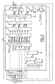
- Figure 1 is the block diagram of the modeling of the production of the engine torque receiving an air flow control C AIRCMD applied to the throttle body 1 which delivers a mass of air entering the manifold 2 and providing a torque, in the form logCMI + logarithm and logCP logarithm, to torque regulator 3.
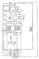
- Figure 2 is the block diagram modeling the torque production of a single-wealth engine.
- control process is carried out during engine operation and consists of regulation of the engine torque developed from the linear model of the engine which has just been described, and of linear type integral quadratic.
- the matrix of state variables X k contains on the one hand the logarithm logC AIRPAP of the quantity C AIRPAP proportional to the mass of air entering the manifold through the throttle body, and that log CAIRMOT of the quantity C AIRMOT proportional to the mass of air leaving the manifold, on the other hand the error of the logarithm of the torque supplied by the engine elogCMI + k-1 , the error of the logarithm of the projected torque elogCP k-1 , the error of the logarithm of the wealth yield for two consecutive high dead points elog ⁇ Ri (k-1 ) and elog ⁇ Ri (k-2 ), and finally the three previously defined integral variables ⁇ logCMI + (k) , ⁇ logCP (k) and ⁇ log ⁇ Ri (k) .
- the disturbance matrix Xs k contains the logarithm of the torque setpoint supplied by the logCMI + cons engine and of the projected torque setpoint logCP cons , and the logarithm of the advance setpoint returns log ⁇ Avcons and the wealth setpoint log ⁇ Ricons .
- the matrix U k of the commands comprises the logarithm logC AIRCMD of the quantity proportional to the actuator control air flow, the logarithms log ⁇ Av and log ⁇ Ri of the ignition advance and of the richness.
- the state return matrix K is calculated from these matrices.
- the representation matrices of the state variables X k , U k and Xs k do not have of variable relating to wealth. They are shown in table 3 in the appendix, while the matrices A, B, F and As which are also simplified are shown in table 4.
- FIG 3 is the block diagram of the device implementing the method of regulating the engine torque according to the invention, in the case of an engine 4 whose throttle body 5 comprises a mechanical throttle 6, including the opening control S p is determined by depressing the accelerator pedal, associated with an additional air valve 7, the opening of which is electronically controlled, in other words section S v .
- FIG. 4 is the same diagram in the case of a motorized throttle valve 8 whose opening S pm is completely controlled.
- the engine 4 receives a command to open the throttle valve S p as well as an electronic command for ignition advance Av, for opening the valve S v and possibly for injection time Ti, and in FIG. 4, the engine receives an opening command S pm from its motorized throttle valve 8.
- the speed value N k and that of the manifold pressure P k or of any other quantity representative of the mass of air actually absorbed by the engine such as the air flow rate, entering the manifold for example.
- the air flow is measured by a flow meter and the manifold pressure is measured by a pressure sensor.
- the electronic engine control computer 9 calculates the mass of air Q AIRMOT leaving the manifold, in means 10, then the richness Ri and the richness yield ⁇ Ri of the mixture from this air mass and the time d injection Ti, in means 11 and 12. From the sections of the butterfly S p and of the valve S v , in the case of FIG.
- the modules 13 of the computer determine the torque values defined above, ie the supplied torque CMI + , the projected torque CP, the torque defined from the mass of air entering the AIRPAP collector C and that leaving the AIRMOT C collector , the instructions for the couples supplied CMI + cons and projected CP cons , the instructions for the wealth returns ⁇ Ricons and in advance ⁇ Avcons and the wealth returns ⁇ Ri .
- Means 14 compute the logarithm of these values which enter into an integral quadratic linear regulator 15, the role of which is to reconstruct the state vector of the torque model and the matrix product to deliver the logarithm of the feed efficiency commands log ⁇ Av , the air flow of the logC actuator AIRCMD and possibly the log ⁇ Ri richness efficiency.
- Means 16 calculate the exponential of these values, which is then clipped in means 17, to take account of the limitations linked to the operation of the actuators and of the motor, which deliver the advance efficiency ⁇ Av , the air control C AIRCMD and the wealth yield ⁇ Ri .
- Means 18 calculate the value of the ignition advance Av from the yield ⁇ Av , the speed N, the manifold pressure P and possibly the richness Ri.
- Means 19 calculate the final control of the air actuator 5, either the section of the valve S v or the opening S pm of the motorized throttle valve.
- Means 20 calculate the richness Ri from the richness yield control ⁇ Ri as well as from a richness yield table as a function of the richness.
- Means 21 then calculate the injection time Ti on the basis of this richness objective and the operating conditions of the engine, such as the pressure in the manifold, the speed, etc. From this injection time, means 22 estimate the richness in each cylinder and the associated richness yield.
- FIGS. 5 and 6 are the same functional diagrams of the regulation device as FIGS. 3 and 4, respectively with a throttle associated with an air valve and with a motorized throttle, but in the case of an engine operating with single richness .
- the wealth yield ⁇ Ri and the wealth yield setpoint ⁇ Ricons are equal to 1.
- a first advantage of the engine control method according to the invention comes from the use of torque control from a non-linear model of the engine, which allows the regulator of the electronic computer to know precisely the effects of controls the behavior of the engine and determine the values of the controls to cause the expected effect.
- the interest of formulating the model of the motor torque, described by multiplicative equations, by a logarithmic function is to obtain a single linear model, which describes in all points the non-linear operation of the motor. This results in a gain in performance for the regulation proposed by the invention compared to the regulations currently existing.
- the regulation of the motor torque is multivariable, that is to say that it acts simultaneously on several control variables to simultaneously regulate several state operating variables.
- each of the state variables is thus regulated taking account of the couplings between the different state and control variables, and it is then possible to exploit the complementarity of the different commands in terms of authority and speed of action.
- Another advantage comes from the definition of the projected engine torque, which makes it possible, in certain operating modes, to position the different commands in advance in a coordinated manner to better respect the engine torque setpoint, by anticipating the dynamics or the delays in the operation of controls.
- this regulation of the engine torque makes it possible, by the addition of simple methods, to take charge of the regulation of other quantities, such as the idling speed, without the development of a complete regulation method acting directly on the actuators.
- This advantage results in a reduction in the complexity and in the size of the processes to be implemented in the electronic engine computer, as well as in a simplification of the procedures for calibration and development of the processes.
Description
L'invention concerne un procédé de contrôle d'un moteur à combustion interne, à allumage commandé et injection pilotée électroniquement, disposant d'au moins trois actionneurs, agissant sur l'avance à l'allumage, la commande de débit d'air du moteur et la richesse du mélange air-essence, et de plusieurs capteurs permettant de déterminer le point de fonctionnement du moteur. Ce procédé de contrôle consiste essentiellement en une régulation du couple fourni par le moteur. Elle concerne également un dispositif de mise en oeuvre de ce procédé.The invention relates to a method for controlling an engine. internal combustion, positive ignition and injection electronically controlled, with at least three actuators, acting on the ignition advance, the engine air flow control and richness of the air-fuel mixture, and several sensors to determine the operating point of the engine. This control process essentially consists by regulating the torque supplied by the motor. She also relates to a device for implementing this process.
Les véhicules automobiles actuels sont dotés de plus en plus d'équipements électroniques et de prestations nouvelles, en plus du contrôle électronique du moteur, telles que la commande électronique de la boíte de vitesse, l'antiblocage de roues lors du freinage ou la régulation électronique de l'air conditionné par exemple. Tous ces équipements induisent des variations importantes du couple consommé, de sorte que le bon fonctionnement du moteur et de ces équipements, associé à l'agrément de conduite du conducteur et au confort des passagers, nécessite de maítriser à tout instant et avec précision le couple délivré par le moteur.Today's motor vehicles are increasingly equipped more electronic equipment and services news, in addition to electronic engine control, such as the electronic control of the gearbox speed, anti-lock braking system when braking or electronic regulation of air conditioning by example. All this equipment induces variations of the torque consumed, so that the correct operation of the engine and associated equipment driver comfort and comfort passengers, requires control at all times and precisely the torque delivered by the engine.
Ce couple délivré par le moteur peut être modulé par variation des valeurs des commandes appliquées aux actionneurs, comme la quantité d'air admis dans le collecteur, la quantité de carburant mélangé à l'air, ou l'instant d'allumage du mélange air/carburant. Ces actionneurs ont des effets différents sur le couple, en termes de rapidité d'action en raison d'un retard pur ou d'un temps de montée, et en termes d'autorité par l'amplitude des effets. Ils ont également des effets sur d'autres grandeurs dont la régulation doit être assurée par ailleurs, telles que la richesse en carburant du mélange combustible, pour des raisons de consommation et de pollution. C'est pourquoi il est souhaitable de limiter l'impact de la régulation du couple moteur sur ces autres grandeurs, tout en utilisant avantageusement plusieurs de ces actionneurs.This torque delivered by the motor can be modulated by variation of command values applied to actuators, such as the amount of air admitted to the manifold, the amount of fuel mixed with air, or the instant of ignition of the air / fuel mixture. These actuators have different effects on the torque, in terms of speed of action due to pure delay or a rise time, and in terms of authority by the magnitude of the effects. They also have effects on other quantities whose regulation must be otherwise assured, such as wealth in fuel of the fuel mixture, for reasons of consumption and pollution. That's why it is desirable to limit the impact of the regulation of engine torque on these other quantities, while advantageously using several of these actuators.
Des solutions actuelles au problème de la régulation du couple moteur utilisent la technologie de régulation dite proportionnelle intégrale dérivée, sans modélisation du moteur, ce qui a pour inconvénient de ne connaítre les effets des commandes appliquées par cette régulation que par l'observation de ses effets sur les grandeurs régulées, entraínant un retard néfaste pour la qualité de la régulation.Current solutions to the problem of regulating engine torque use regulation technology so-called proportional integral derivative, without engine modeling, which has the disadvantage of do not know the effects of commands applied by this regulation only by observing its effects on regulated quantities, causing a delay detrimental to the quality of regulation.
Certaines solutions ont par contre été développées avec un modèle du moteur à partir duquel la régulation peut déterminer les commandes à appliquer, afin d'obtenir un effet désiré sur les grandeurs à réguler.Some solutions have however been developed with an engine model from which regulation can determine the commands to be applied, in order to obtain a desired effect on the quantities to be regulated.
Un exemple de réalisation actuelle de régulation du
couple moteur est décrit dans le brevet européen
EP 0 185 552, au nom de NIPPONDENSO. Le mode de
régulation utilise plusieurs modèles linéaires
identifiés tangents à plusieurs points de
fonctionnement du moteur, destinés à une régulation
multivariable de type linéaire quadratique intégrale
pour réguler le couple moteur en minimisant la
consommation d'essence, à partir des commandes d'air
admis dans le collecteur et d'essence injectée.An example of current implementation of regulation of
engine torque is described in the
Le principal inconvénient de cette solution est dû aux approximations liées à l'utilisation de modèles linéarisés tangents alors que le fonctionnement du moteur n'est pas linéaire, entraínant une dégradation des performances de la régulation du couple.The main disadvantage of this solution is due to approximations related to the use of models linearized tangents while the operation of the motor is not linear, causing degradation torque regulation performance.
De plus, ces modèles n'exploitent pas les connaissances que l'on a des équations physiques décrivant les phénomènes qui interviennent dans le fonctionnement réel du moteur.In addition, these models do not exploit knowledge that we have physical equations describing the phenomena which intervene in the functioning real engine.
Un autre inconvénient de cet exemple de régulation est son coût élevé en raison de l'adjonction d'un capteur de pression de chambre pour mesurer le couple fourni par le moteur.Another disadvantage of this example of regulation is its high cost due to the addition of a sensor chamber pressure to measure the torque supplied by the engine.
L'invention vise à résoudre ces inconvénients en proposant un procédé de contrôle du moteur par une régulation du couple moteur, multivariable de type linéaire quadratique intégrale basée sur un modèle non linéaire du moteur, utilisant comme variables de commandes l'avance à l'allumage et la quantité d'air admis dans le collecteur, et la quantité d'essence injectée dans un cas particulier, et recevant deux consignes de couple calculées simultanément selon le modèle de fonctionnement du moteur.The invention aims to solve these drawbacks by proposing a method of controlling the engine by a motor torque regulation, multivariable type integral quadratic linear based on a non-model linear of the motor, using as variables of controls the ignition advance and the amount of air allowed in the collector, and the quantity of gasoline injected in a particular case, and receiving two torque setpoints calculated simultaneously according to the engine operating model.
Pour cela, un premier objet de l'invention est un procédé de contrôle d'un moteur thermique, à allumage commandé, à injection pilotée par un calculateur électronique, disposant d'au moins trois actionneurs auxquels sont appliqués respectivement une commande d'air, une commande d'allumage et une commande de richesse du mélange combustible, consistant, à partir d'un modèle de la production du couple moteur, en une régulation de type linéaire quadratique intégrale de variables d'état de fonctionnement du moteur par action sur des variables de commande en fonction de variables de consignes et des variables d'état, caractérisé en ce qu'il comporte les étapes suivantes :
- en phase de développement du moteur :
- modélisation dynamique linéaire de la production du couple moteur au moyen d'une fonction logarithme et de sa fonction inverse ;
- définition du gain optimal minimisant l'indice de performance quadratique de la régulation linéaire quadratique intégrale, à partir duquel les variables de commande Uk seront calculées en fonction des variables d'état Xk et de consigne Xsk, et sa mémorisation dans le calculateur ;
- en cours de fonctionnement du moteur, à chaque point
mort haut d'ordre k, calcul des variables d'état Xk
et des consignes Xsk, par le calculateur
électronique, à partir :
- de la mesure du régime Nk et d'une grandeur représentative de la masse d'air absorbée réellement par le moteur, comme la pression collecteur Pk ;
- du calcul de la masse d'air MAIRMOT sortant du collecteur en fonction du régime et de ladite grandeur ;
- du calcul de la richesse et du rendement de richesse à partir du temps d'injection et de la masse d'air MAIRMOT ;
- du calcul de la masse d'air MAIRPAP entrant dans le collecteur en fonction de la masse d'air de commande MAIRCMD de l'actionneur d'air;
- du calcul du couple réel CMI+ et du couple projeté CP fournis par le moteur;
- in engine development phase:
- linear dynamic modeling of the production of the engine torque by means of a logarithmic function and its inverse function;
- definition of the optimal gain minimizing the quadratic performance index of the integral quadratic linear regulation, from which the control variables U k will be calculated as a function of the state variables X k and setpoint Xs k , and its storage in the computer ;
- during engine operation, at each top dead center of order k, calculation of state variables X k and setpoints Xs k , by the electronic computer, from:
- measuring the speed N k and a quantity representative of the mass of air actually absorbed by the engine, such as the manifold pressure P k ;
- calculating the mass of air M AIRMOT leaving the manifold as a function of the speed and of said quantity;
- calculation of the richness and the richness yield from the injection time and the air mass M AIRMOT ;
- calculating the mass of air M AIRPAP entering the manifold as a function of the mass of control air M AIRC® of the air actuator;
- calculating the actual torque CMI + and the projected torque CP supplied by the engine;
Un second objet de l'invention est un dispositif de mise en oeuvre du procédé de régulation du couple moteur, constitué par le calculateur électronique de contrôle du moteur comprenant un régulateur linéaire quadratique intégral.A second object of the invention is a device for implementation of the torque regulation process engine, consisting of the electronic computer of motor control including a linear regulator integral quadratic.
D'autres caractéristiques et avantages de l'invention apparaítront à la lecture de la description du procédé et d'un mode dé réalisation du dispositif de mise en oeuvre du procédé, illustrée par les figures suivantes qui sont :
- figure 1 : le schéma fonctionnel de la modélisation d'un moteur thermique, recevant une commande de débit d'air et fournissant un couple;
- figure 2 : le schéma fonctionnel de la modélisation d'un moteur thermique, qui fonctionne à richesse unique;
- figures 3 et 5 : le schéma fonctionnel du dispositif mettant en oeuvre le procédé de régulation du couple moteur selon l'invention, respectivement avec commande de richesse et richesse constante, dans le cas d'un papillon avec vanne additionnelle d'air ;
- figure 4 et 6 : le schéma fonctionnel mettant en oeuvre le procédé de régulation du couple moteur selon l'invention, respectivement avec commande de richesse et richesse constante, dans le cas d'un papillon motorisé.
- Figure 1: the block diagram of the modeling of a heat engine, receiving an air flow command and providing a torque;
- FIG. 2: the functional diagram of the modeling of a heat engine, which operates at single richness;
- Figures 3 and 5: the block diagram of the device implementing the method of regulating the engine torque according to the invention, respectively with richness control and constant richness, in the case of a butterfly valve with additional air valve;
- FIGS. 4 and 6: the functional diagram implementing the method of regulating the engine torque according to the invention, respectively with richness control and constant richness, in the case of a motorized throttle valve.
La première étape du procédé de régulation du couple moteur consiste à réaliser une modélisation dynamique de la production du couple moteur rendant compte du fonctionnement physique du moteur. cette modélisation est réalisée en phase de développement du moteur, sur banc d'essais.The first step in the torque regulation process engine consists in performing dynamic modeling of the production of the engine torque reflecting the physical operation of the engine. this modeling is performed during the engine development phase, on bench test.
Tout d'abord, le couple fourni par le moteur, à avance
d'allumage optimale et richesse du mélange air-essence
égale à 1, est défini à partir de la masse d'air
MAIRMOT(k) sortant du collecteur d'admission et entrant
dans un cylindre du moteur, à chaque point mort haut
d'ordre k, et du rendement de combustion du moteur
R(Nk,Pk) qui est fonction de la valeur Nk du régime et
de la valeur Pk de la pression dans le collecteur.
Ce couple moteur CAIRMOT(k) est exprimé en
Newton.mètre, selon l'équation suivante (E1) :
- R(Nk,Pk)
- en N.m/kg,
- N
- en tour/min,
- P
- en mbar.
This engine torque C AIRMOT (k) is expressed in Newton meters, according to the following equation (E 1 ):
- R (N k , P k )
- in Nm / kg,
- NOT
- in rev / min,
- P
- in mbar.
Cette valeur doit être corrigée en fonction de l'avance
à l'allumage Av et de la richesse Ri du mélange, par
des rendements d'avance µAv(k) et de richesse µRi(k)
définis à chaque point mort haut d'ordre k, selon
l'équation suivante (E2), de façon à obtenir la valeur
réelle CMI+ du couple fourni par le moteur :
Le rendement de richesse µRi est une fonction cartographiée de la fonction Ri par exemple, et le rendement d'avance µAV est une fonction cartographiée de l'avance, du régime, de la pression collecteur et éventuellement de la richesse.The richness yield µ Ri is a mapped function of the function R i for example, and the advance yield µ AV is a mapped function of the advance, the speed, the manifold pressure and possibly the richness.
Cette expression du couple étant multiplicative, elle
est non-linéaire. Selon l'invention, le procédé en
calcule le logarithme et effectue un changement de
variable. Cela permet, à partir d'équations
multiplicatives, d'utiliser un modèle du couple qui
soit additif sans qu'aucune approximation ne soit
faite. La nouvelle variable est donc le logarithme
logCMI+ du couple, exprimé par l'équation suivante
(E3) :
Selon l'invention est également défini un autre terme
correspondant à une projection du couple précédent
CMI+, quelques points morts hauts plus tard, dans le
but notamment d'anticiper les commandes des actionneurs
lorsque cela est possible. Ce couple projeté CP est
donc défini comme le couple fourni par le moteur, selon
une consigne de rendement d'avance µAvcons et une
consigne de rendement de richesse µRicons, par
l'équation suivante (E4) :
Cette expression du couple étant non linéaire, on en
calcule le logarithme selon l'équation suivante (E5) :
En fonctionnement stabilisé, l'avance et la richesse sont égales à leurs valeurs de consigne, de sorte que le couple projeté CP est égal au couple CMI+.In stabilized operation, the feed rate and the richness are equal to their set values, so that the projected torque CP is equal to the torque CMI + .
Deux consignes de couple sont envoyées au régulateur de couple et sont calculées simultanément, l'une CMI+ cons à partir du couple CMI+ fourni par le moteur et que le régulateur devra suivre le plus rapidement possible, et l'autre CPcons, qui est à plus long terme, à partir du couple projeté CP.Two torque setpoints are sent to the torque regulator and are calculated simultaneously, one CMI + cons from the CMI + torque supplied by the engine and which the regulator must follow as quickly as possible, and the other CP cons , which is in the longer term, from the projected pair CP.
La modélisation du moteur selon l'invention consiste
également à décrire le collecteur d'admission d'air du
moteur par un modèle du premier ordre, à partir de la
masse d'air MAIRPAP entrant dans le collecteur par le
boítier papillon, à chaque point mort haut, que ce
boítier soit constitué par un unique papillon ou bien
qu'il comprenne d'autres actionneurs. Le terme
décrivant le collecteur exprime la masse d'air MAIRMOT
sortant du collecteur pour entrer dans un cylindre,
selon l'équation suivante (E6) :
Pour assurer la compatibilité avec l'écriture du
couple, le modèle du collecteur est relié au couple
CAIRMOT fourni par le moteur et exprimé par l'équation
(E1). Par analogie, il faut définir à partir de la
masse d'air MAIRPAP entrant dans le collecteur,
exprimée en kilogramme, une grandeur homogène à un
couple, selon l'équation suivante (E8) :
En négligeant les variations du rendement de combustion
R(Nk,Pk) du moteur, entre deux points morts hauts
d'indices k et k+1, l'équation (E6) précédente devient:
On admettra que la différence entre les valeurs des
couples CAIRMOT et CAIRPAP, soit CAIRPAP - CAIRMOT, est
petite devant CAIRMOT et que l'on peut utiliser
l'approximation log(1+x) ≈ x, de sorte que le modèle du
collecteur s'écrit selon l'équation suivante (E9) :
Différents actionneurs d'air peuvent être utilisés dans un moteur, comme une vanne RCO, un papillon motorisé ou un stepper. La dynamique de l'actionneur d'air utilisé est décrite comme un modèle du premier ordre, dans le cadre de la modélisation théorique de la production du couple moteur, à partir du débit d'air QAIRPAP entrant dans le collecteur et du débit d'air QAIRCMD de commande de l'actionneur.Different air actuators can be used in an engine, such as an RCO valve, a motorized throttle valve or a stepper. The dynamics of the air actuator used is described as a first-order model, as part of the theoretical modeling of the production of engine torque, from the air flow Q AIRPAP entering the manifold and the flow d air Q AIRCMD actuator control.
L'équation (E10) suivante exprimant le débit d'air
QAIRPAP(k+1) qui entre au point mort haut d'ordre k+1 :
Or, le débit d'air QAIRPAP(k) est relié à la masse
d'air MAIRPAP(k) entrant dans le collecteur par
l'expression (E11) suivante, en fonction de la valeur
Nk du régime moteur et du nombre de cylindres ncyl :
Par analogie, le débit d'air QAIRCMD de commande de
l'actionneur donne lieu à une valeur de couple CAIRCMD
défini selon l'équation suivante (E12) :
Ainsi, l'équation (E10) du débit d'air entrant dans le
collecteur, modélisant le comportement de l'actionneur
d'air, est ramenée sous la forme d'un couple qui
s'écrit, en négligeant les variations du régime N et du
rendement R(Nk,Pk) :
On admettra que la différence entre CAIRPAP et CAIRCMD
reste faible devant CAIRPAP, de sorte que le calcul du
logarithme de CAIRPAP aboutit à l'équation suivante
(E13) :
La production du couple moteur ainsi modélisée selon
l'invention est représentée par les quatre équations
suivantes, représentant respectivement, (E3) le couple
moteur, (E5) le couple projeté, (E9) le fonctionnement
du collecteur et (E13) le fonctionnement de
l'actionneur d'air :
La figure 1 est le schéma fonctionnel de la
modélisation de la production du couple moteur recevant
une commande de débit d'air CAIRCMD appliquée au
boítier papillon 1 qui délivre une masse d'air entrant
dans le collecteur 2 et fournissant un couple, sous
forme du logarithme logCMI+ et du logarithme logCP, au
régulateur de couple 3.Figure 1 is the block diagram of the modeling of the production of the engine torque receiving an air flow control C AIRCMD applied to the
Afin d'assurer le retour des logarithmes du couple
moteur logCMI+, du couple projeté logCP et du rendement
de richesse logµRi vers leurs valeurs de consigne
respectives, l'invention définit trois nouvelles
variables qui sont les intégrales en temps discret de
ces trois grandeurs :
Une variante de réalisation du procédé selon l'invention concerne un fonctionnement du moteur à richesse unique. La figure 2 est le schéma fonctionnel de la modélisation de la production du couple d'un moteur qui fonctionne à richesse unique.An alternative embodiment of the method according to the invention relates to an operation of the engine unique wealth. Figure 2 is the block diagram modeling the torque production of a single-wealth engine.
Selon l'invention, après la phase de développement, le procédé de contrôle est réalisé en cours de fonctionnement du moteur et consiste en une régulation du couple moteur développée à partir du modèle linéaire du moteur qui vient d'être décrit, et de type linéaire quadratique intégrale.According to the invention, after the development phase, the control process is carried out during engine operation and consists of regulation of the engine torque developed from the linear model of the engine which has just been described, and of linear type integral quadratic.
Le modèle linéaire du moteur peut être décrit par sa
représentation d'état :
Uk représente les commandes sur lesquelles pourra agir
le régulateur de couple pour assurer le fonctionnement
du moteur, et
Xsk représente les grandeurs variables qui ont un effet
sur l'état de fonctionnement du moteur, d'après les
équations du modèle du moteur, mais qui ne sont pas
commandées par le régulateur, c'est-à-dire les
perturbations.The linear model of the motor can be described by its state representation:
U k represents the commands on which the torque regulator can act to ensure the operation of the engine, and
Xs k represents the variable quantities which have an effect on the operating state of the engine, according to the equations of the engine model, but which are not controlled by the regulator, that is to say the disturbances.
Ainsi, comme le montre le tableau 1 en annexe, la matrice des variables d'état Xk contient d'une part le logarithme logCAIRPAP de la grandeur CAIRPAP proportionnelle à la masse d'air entrant dans le collecteur par le boítier papillon, et celui logCAIRMOT de la grandeur CAIRMOT proportionnelle à la masse d'air sortant du collecteur, d'autre part l'erreur du logarithme du couple fourni par le moteur elogCMI+ k-1, l'erreur du logarithme du couple projeté elogCPk-1, l'erreur du logarithme du rendement de richesse pour deux points morts hauts consécutifs elogµRi(k-1) et elogµRi(k-2), et enfin les trois variables intégrales précédemment définies ΣlogCMI+ (k), ΣlogCP(k) et ΣlogµRi(k).Thus, as shown in table 1 in the appendix, the matrix of state variables X k contains on the one hand the logarithm logC AIRPAP of the quantity C AIRPAP proportional to the mass of air entering the manifold through the throttle body, and that log CAIRMOT of the quantity C AIRMOT proportional to the mass of air leaving the manifold, on the other hand the error of the logarithm of the torque supplied by the engine elogCMI + k-1 , the error of the logarithm of the projected torque elogCP k-1 , the error of the logarithm of the wealth yield for two consecutive high dead points elogµ Ri (k-1 ) and elogµ Ri (k-2 ), and finally the three previously defined integral variables ΣlogCMI + (k) , ΣlogCP (k) and Σlogµ Ri (k) .
La matrice Xsk des perturbations contient le logarithme de la consigne du couple fourni par le moteur logCMI+ cons et de la consigne du couple projeté logCPcons, et le logarithme des rendements de consigne d'avance logµAvcons et de consigne de richesse logµRicons.The disturbance matrix Xs k contains the logarithm of the torque setpoint supplied by the logCMI + cons engine and of the projected torque setpoint logCP cons , and the logarithm of the advance setpoint returns logµ Avcons and the wealth setpoint logµ Ricons .
La matrice Uk des commandes comprend le logarithme logCAIRCMD de la grandeur proportionnelle au débit d'air de commande de l'actionneur, les logarithmes logµAv et logµRi de l'avance à l'allumage et de la richesse.The matrix U k of the commands comprises the logarithm logC AIRCMD of the quantity proportional to the actuator control air flow, the logarithms logµ Av and logµ Ri of the ignition advance and of the richness.
La régulation linéaire quadratique intégrale est une
régulation à retour d'état, de sorte qu'à chaque
itération, la commande Uk est obtenue à partir d'une
matrice de gain K calculée une fois pour toutes pendant
la phase de développement du régulateur :

La théorie de la régulation linéaire quadratique
intégrale donne la matrice K comme le gain optimal
minimisant l'indice de performance quadratique :

Il est possible d'utiliser plusieurs matrices de gain en fonction du mode de fonctionnement utilisé pour le moteur, privilégiant soit l'avance à l'allumage, la richesse ou l'anti-pollution par exemple.It is possible to use several gain matrices depending on the operating mode used for the engine, favoring either the ignition advance, the wealth or anti-pollution for example.
Quant aux matrices A, B, F et As provenant de la modélisation du moteur pour décrire l'évolution des variables d'état Xk en fonction du temps, elles sont obtenues à partir des quatre équations E3, E5, E9 et E13 précédentes et figurent sur le tableau 2 en annexe. La matrice de retour d'état K est calculée à partir de ces matrices.As for the matrices A, B, F and As coming from the modeling of the engine to describe the evolution of the state variables X k as a function of time, they are obtained from the four equations E 3 , E 5 , E 9 and E 13 above and appear in table 2 in the appendix. The state return matrix K is calculated from these matrices.
Dans le cas particulier d'une commande simplifiée du moteur par l'avance à l'allumage et le débit d'air, à richesse unique, les matrices de représentation des variables d'état Xk, Uk et Xsk ne présentent pas de variable se rapportant à la richesse. Elles figurent sur le tableau 3 en annexe, tandis que les matrices A, B, F et As qui sont également simplifiées figurent sur le tableau 4.In the particular case of a simplified control of the engine by the ignition advance and the air flow, with single richness, the representation matrices of the state variables X k , U k and Xs k do not have of variable relating to wealth. They are shown in table 3 in the appendix, while the matrices A, B, F and As which are also simplified are shown in table 4.
La figure 3 est le schéma fonctionnel du dispositif mettant en oeuvre le procédé de régulation du couple moteur selon l'invention, dans le cas d'un moteur 4 dont le boítier papillon 5 comprend un papillon mécanique 6, dont la commande d'ouverture Sp est déterminée par l'enfoncement de la pédale d'accélérateur, associé à une vanne 7 d'air additionnel, dont on commande électroniquement l'ouverture, autrement dit la section Sv.Figure 3 is the block diagram of the device implementing the method of regulating the engine torque according to the invention, in the case of an engine 4 whose throttle body 5 comprises a mechanical throttle 6, including the opening control S p is determined by depressing the accelerator pedal, associated with an additional air valve 7, the opening of which is electronically controlled, in other words section S v .
La figure 4 est le même schéma dans le cas d'un
papillon motorisé 8 dont on commande totalement
l'ouverture Spm.FIG. 4 is the same diagram in the case of a
Sur la figure 3, le moteur 4 reçoit une commande
d'ouverture du papillon Sp ainsi qu'une commande
électronique d'avance à l'allumage Av, d'ouverture de
la vanne Sv et éventuellement de temps d'injection Ti,
et sur la figure 4, le moteur reçoit une commande
d'ouverture Spm de son papillon motorisé 8. On mesure à
chaque point mort haut d'ordre k, la valeur de régime
Nk et celle de la pression collecteur Pk ou de toute
autre grandeur représentative de la masse d'air
absorbée réellement par le moteur, comme le débit
d'air, entrant dans le collecteur par exemple. Le débit
d'air est mesuré par un débitmètre et la pression
collecteur est mesurée par un capteur de pression. Le
calculateur électronique de contrôle moteur 9 calcule
la masse d'air QAIRMOT sortant du collecteur, dans des
moyens 10, puis la richesse Ri et le rendement de
richesse µRi du mélange à partir de cette masse d'air
et du temps d'injection Ti, dans des moyens 11 et 12. A
partir des sections du papillon Sp et de la vanne Sv,
dans le cas de la figure 3, et à partir de la section
Spm du papillon motorisé dans le cas de la figure 4, de
l'avance Av et du temps d'injection Ti, les modules 13
du calculateur déterminent les valeurs de couple
définis précédemment, soit le couple fourni CMI+, le
couple projeté CP, le couple défini à partir de la
masse d'air entrant dans le collecteur CAIRPAP et celle
sortant du collecteur CAIRMOT, les consignes des
couples fourni CMI+ cons et projeté CPcons, les
consignes des rendements de richesse µRicons et
d'avance µAvcons et le rendement de richesse µRi. Des
moyens 14 calculent le logarithme de ces valeurs qui
entrent dans un régulateur linéaire quadratique
intégral 15, dont le rôle est de reconstituer le
vecteur d'état du modèle de couple et le produit
matriciel pour délivrer le logarithme des commandes de
rendement d'avance logµAv, du débit d'air de
l'actionneur logCAIRCMD et éventuellement de rendement
de richesse logµRi. Des moyens 16 calculent
l'exponentielle de ces valeurs, qui est ensuite écrêtée
dans des moyens 17, pour tenir compte des limitations
liées au fonctionnement des actionneurs et du moteur,
qui délivrent le rendement d'avance µAv, la commande
d'air CAIRCMD et le rendement de richesse µRi.
Des moyens 18 calculent la valeur de l'avance à
l'allumage Av à partir du rendement µAv, du régime N,
de la pression collecteur P et éventuellement de la
richesse Ri.
Des moyens 19 calculent la commande finale de
l'actuateur d'air 5, soit la section de la vanne Sv ou
l'ouverture Spm du papillon motorisé.
Des moyens 20 calculent la richesse Ri à partir de la
commande de rendement de richesse µRi ainsi que d'une
table de rendement de richesse en fonction de la
richesse. Des moyens 21 calculent ensuite le temps
d'injection Ti à partir de cet objectif de richesse et
des conditions de fonctionnement du moteur, telles que
la pression dans le collecteur, le régime, etc ... . A
partir de ce temps d'injection, des moyens 22 estiment
la richesse dans chaque cylindre et le rendement de
richesse associé.In FIG. 3, the engine 4 receives a command to open the throttle valve S p as well as an electronic command for ignition advance Av, for opening the valve S v and possibly for injection time Ti, and in FIG. 4, the engine receives an opening command S pm from its
Means 18 calculate the value of the ignition advance Av from the yield µ Av , the speed N, the manifold pressure P and possibly the richness Ri.
Means 19 calculate the final control of the air actuator 5, either the section of the valve S v or the opening S pm of the motorized throttle valve.
Means 20 calculate the richness Ri from the richness yield control μ Ri as well as from a richness yield table as a function of the richness. Means 21 then calculate the injection time Ti on the basis of this richness objective and the operating conditions of the engine, such as the pressure in the manifold, the speed, etc. From this injection time, means 22 estimate the richness in each cylinder and the associated richness yield.
Les figures 5 et 6 sont les mêmes schémas fonctionnels du dispositif de régulation que les figures 3 et 4, respectivement avec un papillon associé à une vanne d'air et avec un papillon motorisé, mais dans le cas d'un moteur fonctionnant à richesse unique. Le rendement de richesse µRi et la consigne de rendement de richesse µRicons sont égaux à 1.FIGS. 5 and 6 are the same functional diagrams of the regulation device as FIGS. 3 and 4, respectively with a throttle associated with an air valve and with a motorized throttle, but in the case of an engine operating with single richness . The wealth yield µ Ri and the wealth yield setpoint µ Ricons are equal to 1.
Un premier avantage du procédé de contrôle du moteur
selon l'invention vient de l'utilisation d'une
régulation du couple à partir d'un modèle non linéaire
du moteur, ce qui permet au régulateur du calculateur
électronique de connaítre avec précision les effets des
commandes sur le comportement du moteur et de
déterminer les valeurs des commandes afin de provoquer
l'effet attendu.
De plus, l'intérêt de formuler le modèle du couple
moteur, décrit par des équations multiplicatives, par
une fonction logarithme est d'obtenir un modèle
linéaire unique, qui décrit en tous points le
fonctionnement non linéaire du moteur. Ceci se traduit
par un gain en performance pour la régulation proposée
par l'invention par rapport aux régulations existant
actuellement.
D'autre part, la régulation du couple moteur est
multivariable, c'est-à-dire qu'elle agit simultanément
sur plusieurs variables de commande pour réguler
simultanément plusieurs variables d'état du
fonctionnement du moteur. Ceci est particulièrement
avantageux puisque chacune des variables d'état est
ainsi régulée en tenant compte des couplages entre les
différentes variables d'état et de commande, et qu'il
est alors possible d'exploiter la complémentarité des
différentes commandes en termes d'autorité et de
rapidité d'action.
Un autre intérêt provient de la définition du couple
moteur projeté, qui permet dans certains modes de
fonctionnement, de positionner à l'avance les
différentes commandes de façon coordonnée pour mieux
respecter la consigne de couple moteur, en anticipant
la dynamique ou les retards dans le fonctionnement des
commandes.
Enfin, cette régulation du couple moteur permet, par
l'adjonction de procédés simples, de prendre en charge
la régulation d'autres grandeurs, telle que le régime
de ralenti, sans développement d'un procédé complet de
régulation agissant directement sur les actionneurs.
Cet avantage se traduit par une diminution de la
complexité et de la taille des procédés à mettre en
oeuvre dans le calculateur électronique du moteur,
ainsi que par une simplification des procédures de
calibration et de mise au point des procédés.


In addition, the interest of formulating the model of the motor torque, described by multiplicative equations, by a logarithmic function is to obtain a single linear model, which describes in all points the non-linear operation of the motor. This results in a gain in performance for the regulation proposed by the invention compared to the regulations currently existing.
On the other hand, the regulation of the motor torque is multivariable, that is to say that it acts simultaneously on several control variables to simultaneously regulate several state operating variables. This is particularly advantageous since each of the state variables is thus regulated taking account of the couplings between the different state and control variables, and it is then possible to exploit the complementarity of the different commands in terms of authority and speed of action.
Another advantage comes from the definition of the projected engine torque, which makes it possible, in certain operating modes, to position the different commands in advance in a coordinated manner to better respect the engine torque setpoint, by anticipating the dynamics or the delays in the operation of controls.
Finally, this regulation of the engine torque makes it possible, by the addition of simple methods, to take charge of the regulation of other quantities, such as the idling speed, without the development of a complete regulation method acting directly on the actuators. This advantage results in a reduction in the complexity and in the size of the processes to be implemented in the electronic engine computer, as well as in a simplification of the procedures for calibration and development of the processes.
Claims (8)
- Method for control of the torque of an internal combustion engine with spark ignition, with injection controlled by an electronic computer, having at least three actuators to which air control, ignition control and fuel mixture richness control are respectively applied, consisting, from a model of the engine torque, of producing regulation, of the integral quadratic linear type, of variables of the state of operation of the engine by acting upon control variables according to reference variables and state variables, characterised in that it comprises the following steps:in the engine development phase:linear dynamic modelling of the engine torque production by means of a logarithmic function and its inverse function;definition of the optimum gain minimising the quadratic performance index of integral quadratic linear regulation, from which the control variables (UK) will be calculated according to state variables (XK) and reference variables (XsK), and storage thereof in the computer;during operation of the engine, at each top dead centre of the order k, calculation of state variables (XK) and reference variables (XsK) by the electronic computer, from:measurement of the engine speed (NK) and a representative value of the air mass actually absorbed by the engine;calculation of the air mass (MAIRMOT) exiting the manifold according to the engine speed and to said value;calculation of the richness (Ri) and richness efficiency (µRi) from the injection timing and the air mass (MAIRMOT);calculation of the air mass (MAIRPAP) entering into the manifold according to the controlling air mass (MAIRCMD) for the actuator;calculation of the actual torque (CMI+) and the projected torque (CP) supplied by the engine;then calculation of the variables of the controls (UK) according to integral quadratic linear regulation.
- Method for control of torque according to claim 1, characterised in that the value representative of the air mass actually absorbed by the engine is the pressure (PK) in the manifold, or the rate of air entering into the manifold.
- Method for control of torque according to claim 2, characterised in that the modelling of the torque production is defined by four linear equations obtained from the effects produced during the operation of the engine, by:these equations being subsequently linearised by calculation of their logarithm after a change in the variable.the rate of controlling air (QAIRCMD) for the air actuator over the rate of air (QAIRPAP) entering into manifold according to the following first order equation:the air mass (MAIRPAP) entering into the manifold via the throttle valve over the air mass (MAIRMOT) exiting the manifold and entering into a cylinder according to the first order equation:
the air mass (MAIRMOT) exiting the manifold on the one hand over the torque (CMI+) supplied by the engine according to the advance efficiencies (µAV) and richness (µRi) and the engine combustion efficiency R(NK, PK): - Method for control of torque according to claim 3, characterised in that:a) the state variables (XK) of engine operation are:the logarithms of two values homogeneous to a torque, one (CAIRPAP) proportional to the air mass (MAIRPAP) entering into the manifold via the throttle valve and the other (CAIRMOT) proportional to the air mass (MAIRMOT) exiting the manifold;the errors in the torque logarithms supplied by the engine (elogCMI+), in the projected torque (elongCP) and in the richness efficiency (elogµRi) for two consecutive top dead centres, which errors are equal to the difference between the logarithm of the values measured and the logarithm of their respective reference values:three variables defined as the integrals in discrete time of the torque supplied (ΣlogCMI+), of the projected torque (ΣlogCP) and the richness efficiency (ΣlogµRi):b) the reference variables are the logarithms of the reference of torque supplied (logCMI+ cons), of the projected torque (logCPcons), and the efficiencies of ignition advance (logµRicons); andc) the control variables (UK) for the engine actuators are the logarithms (logCAIRCMD) of the value homogenous to a torque and proportional to the rate of air for controlling the actuator, and the efficiencies of ignition advance (logµAv) and richness (logµRi).
- Method for control of the torque according to one of claims I to 4, characterised in that the engine operates at a single richness, with a richness efficiency equalling 1.
- Device for controlling the torque of an internal combustion engine, with spark ignition, with injection controlled by an electronic computer, having at least three actuators to which air control, ignition control and mixture richness control are respectively applied, implementing the method according to one of claims 1 to 5, characterised in that the electronic computer (9) comprises:means (10) for calculating the air mass (MAIRMOT) exiting the manifold;means (11) for calculating the richness (Ri) and means (12) for calculating the efficiency of the richness (µRi) of the mixture from said air mass (MAIRMOT) and the injection timing (Ti);modules (13) determining from the engine speed, the manifold pressure, the opening of the air actuator, the advance (Av) and the injection timing (Ti), values for the torque supplied (CMI+), the projected torque (CAIRPAP) defined from the air mass entering into the manifold, and the torque (CAIRMOT) defined from the air mass exiting the manifold, the references for the torque supplied (CMI+ cons) and the projected torque (CPcons), the references for richness efficiency (µRicons) and the advance efficiency (µAvcons);means (14) for calculating the logarithm of the values calculated by the means (13);an integral quadratic linear regulator (15) receiving at its input the logarithms of the torques calculated by the means (14) and delivering the logarithm of the controls for the advance efficiency (logµAv), the air rate of the actuator (logCAIRCMD) and the richness efficiency (logµRi);means (16) for calculating the exponential of the values delivered by the regulator (15);means (17) for limiting the values delivered by the means (15) in order to take into account the limitations connected with the operation of the actuators and the engine, delivering the advance efficiency (µAv), the air control (CAIRCMD) and the richness efficiency (µRi);means (18) for calculating the value of the ignition advance (Av) from the advance efficiency (µAv), the engine speed (N), the manifold pressure (P) and possibly the richness (Ri);means (19) for calculating the final control (CAIRCMD) of the air actuator (5);means (20) for calculating the richness (Ri) from the control of the richness efficiency (µRi) and from a table of the torque efficiency according to the richness;means (21) for calculating the injection timing (Ti) from said target richness and engine operating conditions such as the pressure in the manifold or the engine speed;means (22) for estimation from the injection timing (Ti), the richness (Ri) in each cylinder, and the associated richness efficiency.
- Device for controlling torque according to claim 6, characterised in that the air actuator is a throttle valve comprising a mechanical throttle (6), the opening (Sp) of which is directly controlled by the accelerator pedal of the vehicle and an additional air valve (7), the opening of which (Sv) is controlled by the electronic computer (9).
- Device for controlling torque according to claim 6, characterised in that the air actuator is a throttle valve comprising a motorised throttle (8) the opening of which (Spm) is controlled by the electronic computer (9).
Applications Claiming Priority (2)
| Application Number | Priority Date | Filing Date | Title |
|---|---|---|---|
| FR9707664 | 1997-06-19 | ||
| FR9707664A FR2764941B1 (en) | 1997-06-19 | 1997-06-19 | METHOD AND DEVICE FOR CONTROLLING AN INTERNAL COMBUSTION ENGINE WITH CONTROLLED IGNITION |
Publications (2)
| Publication Number | Publication Date |
|---|---|
| EP0886055A1 EP0886055A1 (en) | 1998-12-23 |
| EP0886055B1 true EP0886055B1 (en) | 2003-01-22 |
Family
ID=9508192
Family Applications (1)
| Application Number | Title | Priority Date | Filing Date |
|---|---|---|---|
| EP19980401507 Expired - Lifetime EP0886055B1 (en) | 1997-06-19 | 1998-06-19 | Method and apparatus for controlling a spark ignited internal combustion engine |
Country Status (4)
| Country | Link |
|---|---|
| EP (1) | EP0886055B1 (en) |
| DE (1) | DE69810849T2 (en) |
| ES (1) | ES2190571T3 (en) |
| FR (1) | FR2764941B1 (en) |
Families Citing this family (4)
| Publication number | Priority date | Publication date | Assignee | Title |
|---|---|---|---|---|
| FI115203B (en) | 2000-10-02 | 2005-03-31 | Metso Paper Inc | Apparatus for cutting in particular a paper web with water jet |
| FR2944317A3 (en) * | 2009-04-10 | 2010-10-15 | Renault Sas | Gas intake and exhaust system for internal combustion engine of motor vehicle, has control unit controlling valve relative to sensors measurements, where valve is arranged in outlet of exhaust of motor vehicle |
| US9989001B2 (en) | 2012-12-21 | 2018-06-05 | Toyota Motor Engineering & Manufacturing North America, Inc. | Discrete time rate-based model predictive control method for internal combustion engine air path control |
| US9581080B2 (en) * | 2012-12-21 | 2017-02-28 | Toyota Motor Engineering & Manufacturing North America, Inc. | Rate-based model predictive control method for internal combustion engine air path control |
Family Cites Families (2)
| Publication number | Priority date | Publication date | Assignee | Title |
|---|---|---|---|---|
| JPH0697003B2 (en) * | 1984-12-19 | 1994-11-30 | 日本電装株式会社 | Internal combustion engine operating condition control device |
| JP2674077B2 (en) * | 1988-04-12 | 1997-11-05 | トヨタ自動車株式会社 | Non-linear feedback control method for internal combustion engine |
-
1997
- 1997-06-19 FR FR9707664A patent/FR2764941B1/en not_active Expired - Fee Related
-
1998
- 1998-06-19 DE DE1998610849 patent/DE69810849T2/en not_active Expired - Fee Related
- 1998-06-19 EP EP19980401507 patent/EP0886055B1/en not_active Expired - Lifetime
- 1998-06-19 ES ES98401507T patent/ES2190571T3/en not_active Expired - Lifetime
Also Published As
| Publication number | Publication date |
|---|---|
| EP0886055A1 (en) | 1998-12-23 |
| DE69810849D1 (en) | 2003-02-27 |
| FR2764941A1 (en) | 1998-12-24 |
| FR2764941B1 (en) | 1999-08-27 |
| ES2190571T3 (en) | 2003-08-01 |
| DE69810849T2 (en) | 2003-11-13 |
Similar Documents
| Publication | Publication Date | Title |
|---|---|---|
| EP1866537B1 (en) | Method for assisting in srarting a motor vehicle and corresponding device | |
| WO2005008050A1 (en) | Method for real-time determination of fuel injector flow characteristic | |
| FR2659114A1 (en) | METHOD AND DEVICE FOR CONTROLLING THE WEIGHT OF THE AIR / FUEL SUPPLY MIXTURE OF AN INTERNAL COMBUSTION ENGINE. | |
| FR2787511A1 (en) | METHOD AND DEVICE FOR EQUALIZING THE TORQUES OF EACH CYLINDER OF AN ENGINE | |
| EP2148979B1 (en) | Method of controlling the combustion of a diesel engine | |
| EP0886055B1 (en) | Method and apparatus for controlling a spark ignited internal combustion engine | |
| EP0954689B1 (en) | Device for controlling an internal combustion engine with controlled ignition and direct injection | |
| EP1936156B1 (en) | Method of controlling an internal combustion engine | |
| EP1090219B1 (en) | Method for correcting ignition advance of an internal combustion engine | |
| EP2157301B1 (en) | Method for controlling combustion in a diesel engine by means of combustion phasing control | |
| EP1671023B1 (en) | Engine air supply control method which is intended, for example, for the control of a turbocharged engine | |
| FR2902467A1 (en) | Boost pressure regulation system for e.g. heat engine, has unit storing learnt correction values of regulator control signal for considering particle loading variation of filter, and arbitration units triggering reading value | |
| FR2894626A1 (en) | METHOD FOR MANAGING AN INTERNAL COMBUSTION ENGINE | |
| EP1760295B1 (en) | Control system for a diesel engine equipped with exhaust recriculation means | |
| EP1597468B1 (en) | Method for calculating fuel injector gain | |
| EP0736680B1 (en) | Method of self-correction of physical parameters in a dynamic system such as an internal combustion engine | |
| FR2871195A1 (en) | Internal combustion engine monitoring process for motor vehicle, involves adjusting controlled variable on value from requests on engine`s output variable if request different from pedal actuation request exists, or on actuation based value | |
| FR2851298A1 (en) | Thermal engine control process, involves defining mass charging that should be applied to combustion chamber, from bunch of curve characteristics, desired torque, and size explaining desired air/fuel ratio | |
| EP0639704A1 (en) | Method for calculating the mass of air admitted to an internal combustion engine | |
| FR2875271A1 (en) | Drive unit e.g. gasoline engine, controlling method for motor vehicle, involves determining real value of output variable and/or another variable based on valve position, and modeling another value without considering intervention | |
| WO2010125265A1 (en) | Method for controlling the operation of an engine | |
| WO2006064149A1 (en) | Method for controlling a supercharged engine | |
| WO2024047080A1 (en) | Method and system for controlling the engine torque of an internal combustion engine | |
| FR2747429A1 (en) | Control of motor vehicle engine in slowing phase by neural net | |
| EP3805544A1 (en) | Control of a supercharged spark ignition engine with low-pressure exhaust gas recirculation |
Legal Events
| Date | Code | Title | Description |
|---|---|---|---|
| PUAI | Public reference made under article 153(3) epc to a published international application that has entered the european phase |
Free format text: ORIGINAL CODE: 0009012 |
|
| AK | Designated contracting states |
Kind code of ref document: A1 Designated state(s): DE ES GB IT |
|
| AX | Request for extension of the european patent |
Free format text: AL;LT;LV;MK;RO;SI |
|
| 17P | Request for examination filed |
Effective date: 19990527 |
|
| AKX | Designation fees paid |
Free format text: DE ES GB IT |
|
| GRAG | Despatch of communication of intention to grant |
Free format text: ORIGINAL CODE: EPIDOS AGRA |
|
| 17Q | First examination report despatched |
Effective date: 20020409 |
|
| GRAG | Despatch of communication of intention to grant |
Free format text: ORIGINAL CODE: EPIDOS AGRA |
|
| GRAH | Despatch of communication of intention to grant a patent |
Free format text: ORIGINAL CODE: EPIDOS IGRA |
|
| RAP1 | Party data changed (applicant data changed or rights of an application transferred) |
Owner name: RENAULT S.A.S. |
|
| GRAH | Despatch of communication of intention to grant a patent |
Free format text: ORIGINAL CODE: EPIDOS IGRA |
|
| GRAA | (expected) grant |
Free format text: ORIGINAL CODE: 0009210 |
|
| AK | Designated contracting states |
Kind code of ref document: B1 Designated state(s): DE ES GB IT |
|
| PG25 | Lapsed in a contracting state [announced via postgrant information from national office to epo] |
Ref country code: IT Free format text: LAPSE BECAUSE OF FAILURE TO SUBMIT A TRANSLATION OF THE DESCRIPTION OR TO PAY THE FEE WITHIN THE PRE;WARNING: LAPSES OF ITALIAN PATENTS WITH EFFECTIVE DATE BEFORE 2007 MAY HAVE OCCURRED AT ANY TIME BEFORE 2007. THE CORRECT EFFECTIVE DATE MAY BE DIFFERENT FROM THE ONE RECORDED.SCRIBED TIME-LIMIT Effective date: 20030122 Ref country code: GB Free format text: LAPSE BECAUSE OF FAILURE TO SUBMIT A TRANSLATION OF THE DESCRIPTION OR TO PAY THE FEE WITHIN THE PRESCRIBED TIME-LIMIT Effective date: 20030122 |
|
| REG | Reference to a national code |
Ref country code: GB Ref legal event code: FG4D Free format text: NOT ENGLISH |
|
| REF | Corresponds to: |
Ref document number: 69810849 Country of ref document: DE Date of ref document: 20030227 Kind code of ref document: P |
|
| PG25 | Lapsed in a contracting state [announced via postgrant information from national office to epo] |
Ref country code: ES Free format text: LAPSE BECAUSE OF NON-PAYMENT OF DUE FEES Effective date: 20030620 |
|
| GBV | Gb: ep patent (uk) treated as always having been void in accordance with gb section 77(7)/1977 [no translation filed] |
Effective date: 20030122 |
|
| REG | Reference to a national code |
Ref country code: ES Ref legal event code: FG2A Ref document number: 2190571 Country of ref document: ES Kind code of ref document: T3 |
|
| PLBE | No opposition filed within time limit |
Free format text: ORIGINAL CODE: 0009261 |
|
| STAA | Information on the status of an ep patent application or granted ep patent |
Free format text: STATUS: NO OPPOSITION FILED WITHIN TIME LIMIT |
|
| PG25 | Lapsed in a contracting state [announced via postgrant information from national office to epo] |
Ref country code: DE Free format text: LAPSE BECAUSE OF NON-PAYMENT OF DUE FEES Effective date: 20040101 |
|
| 26N | No opposition filed |
Effective date: 20031023 |
|
| REG | Reference to a national code |
Ref country code: ES Ref legal event code: FD2A Effective date: 20030620 |