EP0885664B1 - Roller conveyor - Google Patents
Roller conveyor Download PDFInfo
- Publication number
- EP0885664B1 EP0885664B1 EP98110566A EP98110566A EP0885664B1 EP 0885664 B1 EP0885664 B1 EP 0885664B1 EP 98110566 A EP98110566 A EP 98110566A EP 98110566 A EP98110566 A EP 98110566A EP 0885664 B1 EP0885664 B1 EP 0885664B1
- Authority
- EP
- European Patent Office
- Prior art keywords
- roller conveyor
- rollers
- rows
- containers
- transporting
- Prior art date
- Legal status (The legal status is an assumption and is not a legal conclusion. Google has not performed a legal analysis and makes no representation as to the accuracy of the status listed.)
- Expired - Lifetime
Links
Images

Classifications
-
- B—PERFORMING OPERATIONS; TRANSPORTING
- B07—SEPARATING SOLIDS FROM SOLIDS; SORTING
- B07C—POSTAL SORTING; SORTING INDIVIDUAL ARTICLES, OR BULK MATERIAL FIT TO BE SORTED PIECE-MEAL, e.g. BY PICKING
- B07C3/00—Sorting according to destination
- B07C3/02—Apparatus characterised by the means used for distribution
- B07C3/08—Apparatus characterised by the means used for distribution using arrangements of conveyors
- B07C3/082—In which the objects are carried by transport holders and the transport holders form part of the conveyor belts
- B07C3/087—In which the objects are carried by transport holders and the transport holders form part of the conveyor belts the objects being taken up in transport files or holders which are not part of the conveyor belts
Definitions
- the invention relates to a roller conveyor for Transport of cargo, especially letters Containers, the rolling direction of the rollers of the roller conveyor at a given angle to the direction of transport stands and with the containers by tracking aids against the transverse motion force caused by this angle are kept in the transport direction.
- roller conveyors are known from EP 0 582 964 A2. Cartons are created by the inclination of the rolls against a side stop during transport spent from which position defined measuring and weighing processes to be triggered.
- the object of the invention is an integrable into the conveyor system Roller conveyor of the type mentioned above train that falling cargo, in particular falling out letters that are both in front, behind as well are located directly below the container in the area of this roller conveyor be deposited.
- this object is achieved in that the rollers of the roller conveyor are arranged so closely to one another that in the region of the roller conveyor loads which are not properly placed in a transport container are each supported on at least two rollers and that this cargo is not held by the guidance aids the rolling direction under the guidance aids in at least one located next to the rollers of the roller conveyor is catchable. It is up to the user to decide whether continuous rollers or isolated wheels or belt sections are used.
- the letter separating unit can of course be there Letters are used where experience has shown that letters from the containers are often used fall.
- roller conveyor has two rows is, arranged between the two rows of catch is. This results in the resulting transverse forces the actual container through mutual compensation kept relatively low.
- roller conveyor can be moved by gravity Containers are driven or have active drives.
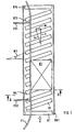
- the roller conveyor can begin and end with usual, arranged transversely to the transport direction with respect to their axes Rollers R1 and R14 be equipped. Essential for that However, the present invention is that between them Roles R1 and R14 arranged further roles from this exact transverse position twisted out by a yaw angle are, in the exemplary embodiment this twist in one Angle W1 may be done.
- Roles R2 to R13 should be identical, but there should always be one Lateral force when transporting the containers, such as container B1, in the direction of a guide F1 that will be guaranteed Guide holder FH1 and FH2 is held stationary.
- the guide F1 is at its ends with inlet curves Capture or release of the containers, such as container B1, provided, but in the area of the inclined rollers R2 up to R13 each container is held by the guide F1 so that it can only move in the direction of transport.
- a vectorial diagram indicates that a Force u of each inclined roll on the respective container a force v in the direction of transport and a force w the respective guide F1 generated.
- rollers R1 up to R14 are so close to each other that fall out Letters lie on the rolls R1 to R14, whereby they, because they cannot lean against F1 leadership, in the direction of the force u, i.e. in the rolling direction of the rolls, be moved. With this, such letters wander under the leadership F1 through and get into a central catch.
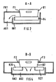
- FIG. 2 shows along the line A-A (FIG 1) shows a side view.
- the same elements are provided here with the same reference numerals, with a curved arrow is indicated, like that not in the container B1 transported letters in a catch AG1 become.
- the container B2 held between guides F2 and F3 is held on guide brackets FH3, FH4, FH5 and FH6 are at best weak against the guides F2 and F3 pressed, which also makes the frictional forces relatively low are.
- Loose cargo, i.e. Letters, outside the container B2 are due to the inclination of the rollers R16 to R39 in a middle aisle between the two rows of rollers and get into a catchment where they can be easily removed can.
- section B-B of FIG. 3 is shown in the illustration of FIG 4, in which the transport of loose letters in a catchment AG2 by two curved ones Arrows is indicated.
- separation can take place of letters that are two-sided on both rows of roller conveyors rest, can be achieved in that the roles of two rows are driven at different speeds, or that the two rows are opposed, but in terms of their absolute size different angular positions exhibit.
Description
Die Erfindung bezieht sich auf einen Rollenförderer zum Transport von Ladungsgut, insbesondere mit Briefen gefüllten Behältern, wobei die Abrollrichtung der Rollen des Rollenförderers in einem jeweils vorgegebenen Winkel zur Transportrichtung steht und wobei die Behälter durch Spurführungshilfen gegen die durch diesen Winkel bedingte Querbewegungskraft in der Transportrichtung gehalten sind.The invention relates to a roller conveyor for Transport of cargo, especially letters Containers, the rolling direction of the rollers of the roller conveyor at a given angle to the direction of transport stands and with the containers by tracking aids against the transverse motion force caused by this angle are kept in the transport direction.
Derartige Rollenförderer sind aus der EP 0 582 964 A2 bekannt. Dabei werden Kartons durch die Schrägstellung der Rollen während des Transports gegen einen seitlichen Anschlag verbracht, von welcher Lage aus definierte Mess- und Wiegevorgänge ausgelöst werden.Such roller conveyors are known from EP 0 582 964 A2. Cartons are created by the inclination of the rolls against a side stop during transport spent from which position defined measuring and weighing processes to be triggered.
Eine Vorrichtung mit derart schräg angeordneten Rollen ist auch in der EP 0 727 371 A1 beschrieben, wobei die Rollen so dicht aneinander angeordnet sind, dass keine Spalte im Transportweg vorhanden sind.A device with such angled rollers is also described in EP 0 727 371 A1, the roles being so are arranged close together so that no gaps in the transport route available.
Wenn in einem komplexen Fördersystem mit Briefen gefüllte Behälter transportiert werden, so ist für dieses Fördergut eine Vielzahl von unterschiedlichen Abmessungen typisch. Dabei ist das Vermeiden eines Herausfallens von Briefen aus den Behältern nicht mit Sicherheit gewährleistet. Ein manuelles Einsammeln der herausgefallenen Briefe im gesamten Förderbereich zieht jedoch eine erhebliche Beeinträchtigung der Funktionalität der gesamten Anlage nach sich.When containers filled with letters in a complex conveyor system are transported, there is one for this material Variety of different dimensions typical. It is preventing letters from falling out of the containers not guaranteed with certainty. A manual collection of the dropped letters in the entire funding area however, draws a significant impairment in functionality the entire system itself.
Aufgabe der Erfindung ist es, einen in das Fördersystem integrierbaren Rollenförderer der eingangs genannten Art so auszubilden, dass herausfallendes Ladungsgut, insbesondere herausfallende Briefe, die sich sowohl vor, hinter als auch unterhalb der Behälter befinden direkt im Bereich dieses Rollenförderers abgeschieden werden.The object of the invention is an integrable into the conveyor system Roller conveyor of the type mentioned above train that falling cargo, in particular falling out letters that are both in front, behind as well are located directly below the container in the area of this roller conveyor be deposited.
Gemäß der Erfindung wird diese Aufgabe dadurch gelöst, dass
die Rollen des Rollenförderers so dicht zueinander angeordnet
sind, dass im Bereich des Rollenförderers auch nicht ordnungsgerecht
in einen Transportbehälter befindliches Ladungsgut
jeweils auf mindestens zwei Rollen aufliegt und dass dieses
somit nicht durch die Spurführungshilfen gehaltene Ladungsgut
in der Abrollrichtung unter die Spurführungshilfen
hindurch in mindestens einen neben den Rollen des Rollenförderers
gelegenen Auf fang verbringbar ist.
Ob dabei durchgängige Rollen oder vereinzelte Räder oder
Bandabschnitte verwendet werden, steht im Belieben des Anwenders.According to the invention, this object is achieved in that the rollers of the roller conveyor are arranged so closely to one another that in the region of the roller conveyor loads which are not properly placed in a transport container are each supported on at least two rollers and that this cargo is not held by the guidance aids the rolling direction under the guidance aids in at least one located next to the rollers of the roller conveyor is catchable.
It is up to the user to decide whether continuous rollers or isolated wheels or belt sections are used.
Die Briefsepariereinheit kann selbstverständlich dort zum Einsatz kommen, wo erfahrungsgemäß häufig Briefe aus den Behältern fallen.The letter separating unit can of course be there Letters are used where experience has shown that letters from the containers are often used fall.
Eine erste vorteilhafte Ausbildung der Erfindung ist dadurch gekennzeichnet, dass der Rollenförderer zweireihig ausgebildet ist, wobei zwischen den beiden Reihen der Auf fang angeordnet ist. Dadurch werden die resultierenden Querkräfte auf den eigentlichen Behälter durch gegenseitige Kompensationswirkung relativ gering gehalten.This is a first advantageous embodiment of the invention characterized in that the roller conveyor has two rows is, arranged between the two rows of catch is. This results in the resulting transverse forces the actual container through mutual compensation kept relatively low.
Prinzipiell kann der Rollenförderer durch die Schwerkraft der Behälter angetrieben werden oder über aktive Antriebe verfügen.In principle, the roller conveyor can be moved by gravity Containers are driven or have active drives.
Wenn ein zweireihiger Rollenförderer so ausgebildet ist, dass die Rollen der beiden Reihen mit unterschiedlicher Geschwindigkeit antreibbar sind, werden sowohl einzelne als auch mehrere zu einer Brücke übereinander gestapelte Briefe, die auf beiden Reihen aufliegen, gegeneinander gedreht und mit Sicherheit im Mittelgang zwischen den Rollen abgeschieden. If a double row roller conveyor is designed so that the roles of the two rows at different speeds can be driven, both individual and several letters stacked on top of each other to form a bridge lie on both rows, turned against each other and with certainty deposited in the middle aisle between the rollers.
Bei zweireihigen Rollenförderern kann jedoch auch durch absolut unterschiedlich große Winkel zur Transportrichtung ein solches Drehen von beide Reihen beaufschlagenden Briefen erreicht werden.In the case of double-row roller conveyors, however, can also be done absolutely different sized angles to the transport direction such turning of letters striking both rows become.
Um Transportgut, insbesondere Briefe, das sich unterhalt der Behälter befindet, trotz des hohen Anpreßdruckes abzuscheiden, erweist es sich als vorteilhaft, daß die Rollen an ihrer Oberfläche ein Material aufweisen, das einen höheren Reibungskoeffizienten gegenüber dem Ladungsgut als gegenüber dem Material der Behälter hat. Dazu können die Rollen beispielsweise mit Kunststoff beschichtet sein.In order to transport goods, especially letters, which are maintained Container is to be separated despite the high contact pressure, it proves to be advantageous that the roles on their Surface have a material that has a higher coefficient of friction towards the cargo than against Material of the container. For example, the roles be coated with plastic.
Ausführungsbeispiele der Erfindung sind in der Zeichnung dargestellt
und werden im folgenden näher erläutert. Dabei zeigen:
In der Darstellung gemäß FIG 1 ist ein Rollenförderer zum Abscheiden von Briefen und Großbriefen gezeigt, der als Abschnitt in die gesamte Fördertechnik einer Briefsortieranlage eingefügt werden kann. Die Förderrichtung, d.h. die Transportrichtung für Behälter mit Briefen, so auch einen Behälter B1, ist in der Darstellung durch einen offenen Pfeil angedeutet. Der Behälter B1 kann wannenförmig ausgebildet sein und bietet in seinem Inneren Platz für das Postgut. Der Rollenförderer kann an seinem Anfang und seinem Ende mit üblichen, hinsichtlich ihrer Achsen quer zur Transportrichtung angeordneten Rollen R1 und R14 ausgestattet sein. Wesentlich für die vorliegende Erfindung ist es aber nun, daß die zwischen diesen Rollen R1 und R14 angeordneten weiteren Rollen aus dieser exakten Querstellung heraus um einen Gierwinkel verdreht sind, wobei im Ausführungsbeispiel diese Verdrehung in einem Winkel W1 erfolgen möge. Dieser muß nicht zwingend für alle Rollen R2 bis R13 identisch sein, jedoch sollte stets eine Querkraft beim Transport der Behälter, so des Behälters B1, in Richtung auf eine Führung F1 gewährleistet sein, die über Führungshalter FH1 und FH2 stationär gehalten ist.1 is a roller conveyor for separation of letters and large letters shown as a section in the entire conveyor technology of a letter sorting system can be inserted. The direction of conveyance, i.e. the direction of transport for containers with letters, including a container B1, is indicated in the illustration by an open arrow. The container B1 can be trough-shaped and offers space for the postal matter inside. The roller conveyor can begin and end with usual, arranged transversely to the transport direction with respect to their axes Rollers R1 and R14 be equipped. Essential for that However, the present invention is that between them Roles R1 and R14 arranged further roles from this exact transverse position twisted out by a yaw angle are, in the exemplary embodiment this twist in one Angle W1 may be done. This does not necessarily have to be for everyone Roles R2 to R13 should be identical, but there should always be one Lateral force when transporting the containers, such as container B1, in the direction of a guide F1 that will be guaranteed Guide holder FH1 and FH2 is held stationary.
Die Führung F1 ist an ihren Enden mit Einlaufrundungen zum Einfangen bzw. Freigeben der Behälter, so des Behälters B1, versehen, jedoch im Bereich der schräggestellten Rollen R2 bis R13 wird jeder Behälter, von der Führung F1 so gehalten, daß es sich nur in der Transportrichtung voranbewegen kann. Durch ein vektorielles Diagramm ist angedeutet, daß eine Kraft u jeder schräggestellten Rolle auf den jeweiligen Behälter eine Kraft v in Transportrichtung und eine Kraft w auf die jeweilige Führung F1 hin erzeugt.The guide F1 is at its ends with inlet curves Capture or release of the containers, such as container B1, provided, but in the area of the inclined rollers R2 up to R13 each container is held by the guide F1 so that it can only move in the direction of transport. A vectorial diagram indicates that a Force u of each inclined roll on the respective container a force v in the direction of transport and a force w the respective guide F1 generated.
Jeder Behälter wird also in Transportrichtung vorangeschoben, reibt jedoch an der Führung F1 entlang. Um die Reibung zwischen Behälter und Führung F1 gering zu halten, kann diese eine entsprechende Materialbeschaffenheit aufweisen oder auch durch der Übersichtlichkeit halber nicht dargestellte Röllchen bestückt sein.So each container is pushed forward in the direction of transport, but rubs against the F1 guide. To the friction between Keeping the container and guide F1 low can do this have a corresponding material quality or also due to the clarity rolls not shown be equipped.
Wesentlich für die Erfindung ist es auch, daß die Rollen R1 bis R14 so dicht nebeneinander angeordnet sind, daß herausgefallene Briefe auf den Rollen R1 bis R14 aufliegen, wodurch sie, da sie sich nicht gegen die Führung F1 abstützen können, in Richtung der Kraft u, d.h. in Abrollrichtung der Rollen, bewegt werden. Damit wandern solche Briefe unter der Führung F1 hindurch und gelangen in einen zentralen Auf fang.It is also essential for the invention that the rollers R1 up to R14 are so close to each other that fall out Letters lie on the rolls R1 to R14, whereby they, because they cannot lean against F1 leadership, in the direction of the force u, i.e. in the rolling direction of the rolls, be moved. With this, such letters wander under the leadership F1 through and get into a central catch.
Um dies zu verdeutlichen, ist in FIG 2 entlang der Linie A-A (FIG 1) eine Seitenansicht gezeigt. Gleiche Elemente sind auch hier mit gleichen Bezugszeichen versehen, wobei durch einen gebogenen Pfeil angedeutet ist, wie die nicht im Behälter B1 befindlichen Briefe in einen Auffang AG1 transportiert werden. Dieser kann durch der Übersichtlichkeit halber nicht gezeigte weitere Transporteinrichtungen, beispielsweise Bänder, fortlaufend geleert werden, jedoch könnte er auch wegen seiner definierten Lage und Größe problemlos bei laufendem Betrieb der Anlage manuell bedient werden.To make this clear, FIG. 2 shows along the line A-A (FIG 1) shows a side view. The same elements are provided here with the same reference numerals, with a curved arrow is indicated, like that not in the container B1 transported letters in a catch AG1 become. For reasons of clarity, this cannot shown further transport devices, for example belts, be emptied continuously, but it could also be because of its defined position and size without problems while running Operation of the system can be operated manually.
In der Darstellung gemäß FIG 3 ist gezeigt, daß auch eine zweireihige Anordnung eines Rollenförderers denkbar ist, wodurch die resultierende Querkraft auf einen dortigen Behälter B2 aufgrund einer gegenseitigen Kompensation relativ gering ist. Beim dargestellten Ausführungsbeispiel ist am Einlauf des Rollenförderers eine übliche durchgängige Rolle R15 und am Auslauf eine eben solche Rolle R40 vorgesehen, jedoch befinden sich zwischen diesen Rollen R15 und R40 eine erste Reihe Rollen R16 bis R38, die in einem Winkel W2 schräggestellt sein mögen und parallel dazu an der anderen Seite des Rollenförderers eine zweite Reihe von Rollen R17 bis R39, die um einen gleichgroßen, aber gegensinnigen Winkel W3 schräggestellt sind.In the representation according to FIG 3 it is shown that a double row arrangement of a roller conveyor is conceivable, whereby the resulting shear force on a container there B2 relatively low due to mutual compensation is. In the illustrated embodiment is at the inlet of the roller conveyor a usual continuous roller R15 and A roll R40 of this type is provided at the outlet, but is located a first between these roles R15 and R40 Row of rollers R16 to R38, which are inclined at an angle W2 may be and in parallel on the other side of the Roller conveyor a second row of rollers R17 to R39, the inclined by an equally large but opposite angle W3 are.
Der Behälter B2, der zwischen Führungen F2 und F3 gehalten ist, die an Führungshaltern FH3, FH4, FH5 und FH6 gehalten sind, wird dadurch allenfalls schwach gegen die Führungen F2 und F3 gepreßt, wodurch auch die Reibkräfte relativ gering sind. Loses Ladungsgut, d.h. Briefe, außerhalb des Behälters B2 werden durch die Schrägstellung der Rollen R16 bis R39 in einen Mittelgang zwischen den beiden Rollenreihen verbracht und gelangen in einen Auffang, wo sie leicht entnommen werden können. Um dies darzustellen, ist ein Schnitt B-B der FIG 3 in der Darstellung gemäß FIG 4 gezeigt, bei dem das Transportieren von losen Briefen in einen Auffang AG2 durch zwei gebogene Pfeile angedeutet ist. The container B2 held between guides F2 and F3 is held on guide brackets FH3, FH4, FH5 and FH6 are at best weak against the guides F2 and F3 pressed, which also makes the frictional forces relatively low are. Loose cargo, i.e. Letters, outside the container B2 are due to the inclination of the rollers R16 to R39 in a middle aisle between the two rows of rollers and get into a catchment where they can be easily removed can. To illustrate this, section B-B of FIG. 3 is shown in the illustration of FIG 4, in which the transport of loose letters in a catchment AG2 by two curved ones Arrows is indicated.
Bei der Anordnung gemäß FIG 3 und FIG 4 kann ein Abscheiden von Briefen, die zweiseitig auf beiden Reihen der Rollenförderer aufliegen, dadurch erreicht werden, daß die Rollen der beiden Reihen unterschiedlich schnell angetrieben werden, oder daß die beiden Reihen zwar gegensinnige, jedoch hinsichtlich ihrer absoluten Größe unterschiedliche Winkelstellungen aufweisen.In the arrangement according to FIG. 3 and FIG. 4, separation can take place of letters that are two-sided on both rows of roller conveyors rest, can be achieved in that the roles of two rows are driven at different speeds, or that the two rows are opposed, but in terms of their absolute size different angular positions exhibit.
Claims (5)
- Roller conveyor for transporting loads, in particular containers filled with letters, it being the case that the rolling direction of the rollers of the roller conveyor is located at a respectively predetermined angle to the transporting direction, that the containers are retained in the transporting direction, counter to the transverse-movement force resulting from this angle, by track-guide aids, and that the rollers (R1 to R40) of the roller conveyor are arranged so closely to one another that, in the region of the roller conveyor, even loads which are not located correctly in a transporting container rest on at least two rollers in each case, characterized in that the loads which are not located in the transporting containers and thus are not guided by the track-guide aids (F1, F2, F3) can be moved through, in the rolling direction, beneath the track-guide aids (F1, F2, F3) into at least one receiving hopper (AG1, AG2) located alongside the rollers of the roller conveyor.
- Roller conveyor according to Claim 1, characterized in that the roller conveyor is designed in two rows, the receiving hopper (AG2) being arranged between the two rows.
- Roller conveyor according to Claim 2, characterized in that the rollers of the two rows of the roller conveyor can be driven at different speeds.
- Roller conveyor according to Claim 2 or 3, characterized in that the two rows of the roller conveyor are angled in relation to the transporting direction by different absolute values.
- Roller conveyor according to one of the preceding claims, characterized in that the rollers (R1 to R90), on their surface, have a material of which the coefficient of friction is higher in relation to the loads than in relation to the material of the containers (B1, B2).
Applications Claiming Priority (2)
| Application Number | Priority Date | Filing Date | Title |
|---|---|---|---|
| DE29710813U | 1997-06-20 | ||
| DE29710813U DE29710813U1 (en) | 1997-06-20 | 1997-06-20 | Roller conveyor |
Publications (3)
| Publication Number | Publication Date |
|---|---|
| EP0885664A2 EP0885664A2 (en) | 1998-12-23 |
| EP0885664A3 EP0885664A3 (en) | 1999-04-21 |
| EP0885664B1 true EP0885664B1 (en) | 2002-08-28 |
Family
ID=8041946
Family Applications (1)
| Application Number | Title | Priority Date | Filing Date |
|---|---|---|---|
| EP98110566A Expired - Lifetime EP0885664B1 (en) | 1997-06-20 | 1998-06-09 | Roller conveyor |
Country Status (2)
| Country | Link |
|---|---|
| EP (1) | EP0885664B1 (en) |
| DE (2) | DE29710813U1 (en) |
Families Citing this family (2)
| Publication number | Priority date | Publication date | Assignee | Title |
|---|---|---|---|---|
| EP3656705A1 (en) | 2017-03-27 | 2020-05-27 | BEUMER Group GmbH & Co. KG | Conveyor device for combining piece goods from multiple feed belts |
| CN110026343A (en) * | 2019-05-17 | 2019-07-19 | 哈工大机器人(合肥)国际创新研究院 | A kind of monoblock type unilateral side pre-sorting equipment |
Family Cites Families (4)
| Publication number | Priority date | Publication date | Assignee | Title |
|---|---|---|---|---|
| US4039074A (en) * | 1975-11-05 | 1977-08-02 | Rapistan, Incorporated | Unscrambler for randomly arranged packages |
| DE3023008A1 (en) * | 1980-06-20 | 1982-01-07 | Mohndruck, Graphische Betriebe GmbH, 4830 Gütersloh | Conveyor switch points installation - is fitted with two inclined roller tracks arranged in V=shape and with backward angled rollers for books transport |
| US5201397A (en) * | 1990-10-05 | 1993-04-13 | Electrocom Automation L.P. | Method and apparatus for separating a stack of products into a stream of single products for sorting |
| DE69613727T2 (en) * | 1995-02-14 | 2001-11-29 | Santrade Ltd | Device for removing objects which are conveyed in parallel next to other objects |
-
1997
- 1997-06-20 DE DE29710813U patent/DE29710813U1/en not_active Expired - Lifetime
-
1998
- 1998-06-09 DE DE59805289T patent/DE59805289D1/en not_active Expired - Fee Related
- 1998-06-09 EP EP98110566A patent/EP0885664B1/en not_active Expired - Lifetime
Also Published As
| Publication number | Publication date |
|---|---|
| EP0885664A3 (en) | 1999-04-21 |
| EP0885664A2 (en) | 1998-12-23 |
| DE59805289D1 (en) | 2002-10-02 |
| DE29710813U1 (en) | 1997-08-14 |
Similar Documents
| Publication | Publication Date | Title |
|---|---|---|
| DE3303184C2 (en) | ||
| EP0616961B1 (en) | High speed separating and aligning device for articles | |
| DE3232039A1 (en) | DEVICE FOR CONVEYING SORTED, STACKED GOODS | |
| EP0804365A1 (en) | Process and device for rotating rotationally symmetrical containers such as bottles during transport under dynamic pressure | |
| WO2010043720A1 (en) | Device for separating and aligning the position of metal container seals | |
| DD211963A5 (en) | DEVICE FOR SORTING LONG-SECTION PARTS | |
| DE102008057901A1 (en) | carrier | |
| DE4314462C2 (en) | Device for the vertical positioning of can bodies | |
| DE3306815C2 (en) | DEVICE FOR TRANSPORTING FLAT PRODUCTS INCLUDED IN A DANDEL INFORMATION, IN PARTICULAR PRINTED PRODUCTS | |
| DE3512694C2 (en) | Device for handling rod-shaped objects | |
| DE1146793B (en) | Device for arranging (straightening) conical textile sleeves, spools of thread or other elongated objects with ends of unequal thickness | |
| DE10212024A1 (en) | Device to separate flat objects e.g. letters or flat parcels, consists of continuous handling belt with carrier surface and separator belt with separator surface moving in opposite directions, to generate speed differential between letters | |
| DE2838896C2 (en) | ||
| EP3450355B1 (en) | Conveying plant | |
| DE2015512A1 (en) | Transfer device for containers between a first and a second conveyor | |
| EP0885664B1 (en) | Roller conveyor | |
| EP3676205B1 (en) | Method and device for transferring transported materials between two conveyor devices, and conveyor system | |
| EP2174897B1 (en) | Device for guiding returnable containers | |
| EP2808275A1 (en) | Conveying device for containers and method for guiding containers from a first to a second transport direction | |
| DE10127109B4 (en) | Device for removing and separating bags from pile carriers | |
| DD297941A5 (en) | KIT FOR THE RETROFITTING OF ROLLER HOLLOWERS | |
| DE10015566A1 (en) | Conveyor system for bottles has side supports which move in same direction as conveyor | |
| DE3709547A1 (en) | Apparatus for sorting sheet-like articles | |
| DE10001556A1 (en) | Unit for transporting and sorting flat objects such as folding box blanks used on confectionery line has oppositely disposed runs of conveyor belts arranged to include acute angle when viewed at right angles to transporting direction | |
| EP2615587B1 (en) | Device for handling coins with a drop protection unit |
Legal Events
| Date | Code | Title | Description |
|---|---|---|---|
| PUAI | Public reference made under article 153(3) epc to a published international application that has entered the european phase |
Free format text: ORIGINAL CODE: 0009012 |
|
| AK | Designated contracting states |
Kind code of ref document: A2 Designated state(s): DE FR IT |
|
| AX | Request for extension of the european patent |
Free format text: AL;LT;LV;MK;RO;SI |
|
| PUAL | Search report despatched |
Free format text: ORIGINAL CODE: 0009013 |
|
| AK | Designated contracting states |
Kind code of ref document: A3 Designated state(s): AT BE CH CY DE DK ES FI FR GB GR IE IT LI LU MC NL PT SE |
|
| AX | Request for extension of the european patent |
Free format text: AL;LT;LV;MK;RO;SI |
|
| 17P | Request for examination filed |
Effective date: 19990520 |
|
| AKX | Designation fees paid |
Free format text: DE FR IT |
|
| 17Q | First examination report despatched |
Effective date: 20010619 |
|
| GRAG | Despatch of communication of intention to grant |
Free format text: ORIGINAL CODE: EPIDOS AGRA |
|
| GRAG | Despatch of communication of intention to grant |
Free format text: ORIGINAL CODE: EPIDOS AGRA |
|
| GRAH | Despatch of communication of intention to grant a patent |
Free format text: ORIGINAL CODE: EPIDOS IGRA |
|
| GRAH | Despatch of communication of intention to grant a patent |
Free format text: ORIGINAL CODE: EPIDOS IGRA |
|
| GRAA | (expected) grant |
Free format text: ORIGINAL CODE: 0009210 |
|
| AK | Designated contracting states |
Kind code of ref document: B1 Designated state(s): DE FR IT |
|
| PG25 | Lapsed in a contracting state [announced via postgrant information from national office to epo] |
Ref country code: IT Free format text: LAPSE BECAUSE OF FAILURE TO SUBMIT A TRANSLATION OF THE DESCRIPTION OR TO PAY THE FEE WITHIN THE PRE;WARNING: LAPSES OF ITALIAN PATENTS WITH EFFECTIVE DATE BEFORE 2007 MAY HAVE OCCURRED AT ANY TIME BEFORE 2007. THE CORRECT EFFECTIVE DATE MAY BE DIFFERENT FROM THE ONE RECORDED.SCRIBED TIME-LIMIT Effective date: 20020828 Ref country code: FR Free format text: LAPSE BECAUSE OF NON-PAYMENT OF DUE FEES Effective date: 20020828 |
|
| REF | Corresponds to: |
Ref document number: 59805289 Country of ref document: DE Date of ref document: 20021002 |
|
| EN | Fr: translation not filed | ||
| PLBE | No opposition filed within time limit |
Free format text: ORIGINAL CODE: 0009261 |
|
| STAA | Information on the status of an ep patent application or granted ep patent |
Free format text: STATUS: NO OPPOSITION FILED WITHIN TIME LIMIT |
|
| 26N | No opposition filed |
Effective date: 20030530 |
|
| PG25 | Lapsed in a contracting state [announced via postgrant information from national office to epo] |
Ref country code: DE Free format text: LAPSE BECAUSE OF NON-PAYMENT OF DUE FEES Effective date: 20040101 |