EP0885336B1 - Hybride platte und herstellungsverfahren - Google Patents
Hybride platte und herstellungsverfahren Download PDFInfo
- Publication number
- EP0885336B1 EP0885336B1 EP97906092A EP97906092A EP0885336B1 EP 0885336 B1 EP0885336 B1 EP 0885336B1 EP 97906092 A EP97906092 A EP 97906092A EP 97906092 A EP97906092 A EP 97906092A EP 0885336 B1 EP0885336 B1 EP 0885336B1
- Authority
- EP
- European Patent Office
- Prior art keywords
- composite material
- volume
- hybrid
- particles
- composite
- Prior art date
- Legal status (The legal status is an assumption and is not a legal conclusion. Google has not performed a legal analysis and makes no representation as to the accuracy of the status listed.)
- Expired - Lifetime
Links
- 238000004519 manufacturing process Methods 0.000 title claims description 14
- 239000002131 composite material Substances 0.000 claims abstract description 269
- 239000002245 particle Substances 0.000 claims abstract description 93
- 230000002787 reinforcement Effects 0.000 claims abstract description 60
- 239000004568 cement Substances 0.000 claims abstract description 55
- 239000004033 plastic Substances 0.000 claims abstract description 24
- 229920003023 plastic Polymers 0.000 claims abstract description 24
- 229910052751 metal Inorganic materials 0.000 claims abstract description 22
- 239000002184 metal Substances 0.000 claims abstract description 22
- 150000002739 metals Chemical class 0.000 claims abstract description 4
- 239000011435 rock Substances 0.000 claims abstract description 4
- 239000000919 ceramic Substances 0.000 claims abstract description 3
- 229910000831 Steel Inorganic materials 0.000 claims description 143
- 239000010959 steel Substances 0.000 claims description 143
- 239000000463 material Substances 0.000 claims description 96
- 238000010276 construction Methods 0.000 claims description 75
- 238000011068 loading method Methods 0.000 claims description 64
- 239000011230 binding agent Substances 0.000 claims description 48
- 238000000034 method Methods 0.000 claims description 26
- 239000010419 fine particle Substances 0.000 claims description 17
- 230000008569 process Effects 0.000 claims description 15
- 229910021487 silica fume Inorganic materials 0.000 claims description 12
- VYPSYNLAJGMNEJ-UHFFFAOYSA-N silicon dioxide Inorganic materials O=[Si]=O VYPSYNLAJGMNEJ-UHFFFAOYSA-N 0.000 claims description 12
- 238000010521 absorption reaction Methods 0.000 claims description 8
- 239000004411 aluminium Substances 0.000 claims description 8
- 229910052782 aluminium Inorganic materials 0.000 claims description 8
- XAGFODPZIPBFFR-UHFFFAOYSA-N aluminium Chemical compound [Al] XAGFODPZIPBFFR-UHFFFAOYSA-N 0.000 claims description 8
- PNEYBMLMFCGWSK-UHFFFAOYSA-N aluminium oxide Inorganic materials [O-2].[O-2].[O-2].[Al+3].[Al+3] PNEYBMLMFCGWSK-UHFFFAOYSA-N 0.000 claims description 5
- 239000011398 Portland cement Substances 0.000 claims description 4
- 229910045601 alloy Inorganic materials 0.000 claims description 4
- 239000000956 alloy Substances 0.000 claims description 4
- 229910052581 Si3N4 Inorganic materials 0.000 claims description 3
- 239000010438 granite Substances 0.000 claims description 3
- 239000010453 quartz Substances 0.000 claims description 3
- HBMJWWWQQXIZIP-UHFFFAOYSA-N silicon carbide Chemical compound [Si+]#[C-] HBMJWWWQQXIZIP-UHFFFAOYSA-N 0.000 claims description 3
- 229910010271 silicon carbide Inorganic materials 0.000 claims description 3
- HQVNEWCFYHHQES-UHFFFAOYSA-N silicon nitride Chemical compound N12[Si]34N5[Si]62N3[Si]51N64 HQVNEWCFYHHQES-UHFFFAOYSA-N 0.000 claims description 3
- 230000003068 static effect Effects 0.000 claims description 3
- 150000004645 aluminates Chemical class 0.000 claims description 2
- PXHVJJICTQNCMI-UHFFFAOYSA-N Nickel Chemical compound [Ni] PXHVJJICTQNCMI-UHFFFAOYSA-N 0.000 claims 2
- 229910052755 nonmetal Inorganic materials 0.000 claims 2
- RYGMFSIKBFXOCR-UHFFFAOYSA-N Copper Chemical compound [Cu] RYGMFSIKBFXOCR-UHFFFAOYSA-N 0.000 claims 1
- RTAQQCXQSZGOHL-UHFFFAOYSA-N Titanium Chemical compound [Ti] RTAQQCXQSZGOHL-UHFFFAOYSA-N 0.000 claims 1
- 229910052802 copper Inorganic materials 0.000 claims 1
- 239000010949 copper Substances 0.000 claims 1
- 239000013078 crystal Substances 0.000 claims 1
- 229910052759 nickel Inorganic materials 0.000 claims 1
- 239000010936 titanium Substances 0.000 claims 1
- 229910052719 titanium Inorganic materials 0.000 claims 1
- 230000001976 improved effect Effects 0.000 abstract description 6
- 230000008901 benefit Effects 0.000 abstract description 5
- 239000004567 concrete Substances 0.000 description 127
- 230000006399 behavior Effects 0.000 description 52
- 230000009471 action Effects 0.000 description 31
- 238000004364 calculation method Methods 0.000 description 26
- 238000005452 bending Methods 0.000 description 24
- 238000006073 displacement reaction Methods 0.000 description 21
- 230000000694 effects Effects 0.000 description 16
- 238000012360 testing method Methods 0.000 description 16
- 238000002474 experimental method Methods 0.000 description 13
- XLYOFNOQVPJJNP-UHFFFAOYSA-N water Substances O XLYOFNOQVPJJNP-UHFFFAOYSA-N 0.000 description 13
- 238000007906 compression Methods 0.000 description 11
- 230000006835 compression Effects 0.000 description 11
- 230000006872 improvement Effects 0.000 description 10
- 239000007788 liquid Substances 0.000 description 10
- 230000005540 biological transmission Effects 0.000 description 9
- 230000006870 function Effects 0.000 description 9
- 238000002156 mixing Methods 0.000 description 9
- 239000000203 mixture Substances 0.000 description 9
- 239000004576 sand Substances 0.000 description 9
- 239000011159 matrix material Substances 0.000 description 8
- 239000004570 mortar (masonry) Substances 0.000 description 8
- 238000000465 moulding Methods 0.000 description 8
- 238000006243 chemical reaction Methods 0.000 description 7
- 238000013461 design Methods 0.000 description 7
- 238000005516 engineering process Methods 0.000 description 7
- 238000000926 separation method Methods 0.000 description 7
- 238000004026 adhesive bonding Methods 0.000 description 6
- 229910001570 bauxite Inorganic materials 0.000 description 6
- 239000000835 fiber Substances 0.000 description 6
- 238000004080 punching Methods 0.000 description 6
- 238000007493 shaping process Methods 0.000 description 6
- 239000003292 glue Substances 0.000 description 5
- 239000000853 adhesive Substances 0.000 description 4
- 230000001070 adhesive effect Effects 0.000 description 4
- 238000004873 anchoring Methods 0.000 description 4
- 230000015572 biosynthetic process Effects 0.000 description 4
- 238000011156 evaluation Methods 0.000 description 4
- 238000010348 incorporation Methods 0.000 description 4
- 238000005259 measurement Methods 0.000 description 4
- 230000007246 mechanism Effects 0.000 description 4
- 239000000843 powder Substances 0.000 description 4
- 239000011150 reinforced concrete Substances 0.000 description 4
- 239000004575 stone Substances 0.000 description 4
- 239000000126 substance Substances 0.000 description 4
- 238000013459 approach Methods 0.000 description 3
- 239000011362 coarse particle Substances 0.000 description 3
- 239000002270 dispersing agent Substances 0.000 description 3
- 239000011521 glass Substances 0.000 description 3
- 238000010438 heat treatment Methods 0.000 description 3
- 238000005304 joining Methods 0.000 description 3
- 238000002360 preparation method Methods 0.000 description 3
- 238000007711 solidification Methods 0.000 description 3
- 230000008023 solidification Effects 0.000 description 3
- 238000002834 transmittance Methods 0.000 description 3
- 229910052593 corundum Inorganic materials 0.000 description 2
- 238000005520 cutting process Methods 0.000 description 2
- 239000004744 fabric Substances 0.000 description 2
- 230000036571 hydration Effects 0.000 description 2
- 238000006703 hydration reaction Methods 0.000 description 2
- 230000003993 interaction Effects 0.000 description 2
- 230000009467 reduction Effects 0.000 description 2
- 239000005060 rubber Substances 0.000 description 2
- 239000007787 solid Substances 0.000 description 2
- 238000005507 spraying Methods 0.000 description 2
- 239000011882 ultra-fine particle Substances 0.000 description 2
- 238000003466 welding Methods 0.000 description 2
- 229910001845 yogo sapphire Inorganic materials 0.000 description 2
- 229910001294 Reinforcing steel Inorganic materials 0.000 description 1
- 229910020489 SiO3 Inorganic materials 0.000 description 1
- 241000826860 Trapezium Species 0.000 description 1
- 230000035508 accumulation Effects 0.000 description 1
- 238000009825 accumulation Methods 0.000 description 1
- 238000004458 analytical method Methods 0.000 description 1
- 238000005119 centrifugation Methods 0.000 description 1
- 239000003795 chemical substances by application Substances 0.000 description 1
- 238000005229 chemical vapour deposition Methods 0.000 description 1
- 238000004140 cleaning Methods 0.000 description 1
- 239000011248 coating agent Substances 0.000 description 1
- 238000000576 coating method Methods 0.000 description 1
- 238000007796 conventional method Methods 0.000 description 1
- 238000001816 cooling Methods 0.000 description 1
- 230000006378 damage Effects 0.000 description 1
- 230000007423 decrease Effects 0.000 description 1
- 230000001419 dependent effect Effects 0.000 description 1
- 238000011161 development Methods 0.000 description 1
- 238000007580 dry-mixing Methods 0.000 description 1
- 230000008030 elimination Effects 0.000 description 1
- 238000003379 elimination reaction Methods 0.000 description 1
- 238000009472 formulation Methods 0.000 description 1
- 239000012634 fragment Substances 0.000 description 1
- 239000010440 gypsum Substances 0.000 description 1
- 229910052602 gypsum Inorganic materials 0.000 description 1
- 238000001764 infiltration Methods 0.000 description 1
- 230000008595 infiltration Effects 0.000 description 1
- 230000000977 initiatory effect Effects 0.000 description 1
- 230000002427 irreversible effect Effects 0.000 description 1
- 239000011344 liquid material Substances 0.000 description 1
- 230000004807 localization Effects 0.000 description 1
- 230000010355 oscillation Effects 0.000 description 1
- 238000007750 plasma spraying Methods 0.000 description 1
- 239000002985 plastic film Substances 0.000 description 1
- 230000008092 positive effect Effects 0.000 description 1
- 230000000063 preceeding effect Effects 0.000 description 1
- 230000003014 reinforcing effect Effects 0.000 description 1
- 230000002441 reversible effect Effects 0.000 description 1
- 230000000630 rising effect Effects 0.000 description 1
- 230000009291 secondary effect Effects 0.000 description 1
- 238000009416 shuttering Methods 0.000 description 1
- 239000007779 soft material Substances 0.000 description 1
- 238000005476 soldering Methods 0.000 description 1
- 239000011343 solid material Substances 0.000 description 1
- 238000003892 spreading Methods 0.000 description 1
- 230000007480 spreading Effects 0.000 description 1
- 238000005728 strengthening Methods 0.000 description 1
- 239000000758 substrate Substances 0.000 description 1
- 239000008399 tap water Substances 0.000 description 1
- 235000020679 tap water Nutrition 0.000 description 1
- 239000012815 thermoplastic material Substances 0.000 description 1
- 229920001187 thermosetting polymer Polymers 0.000 description 1
- 230000000007 visual effect Effects 0.000 description 1
- 239000002023 wood Substances 0.000 description 1
Images


Classifications
-
- E—FIXED CONSTRUCTIONS
- E04—BUILDING
- E04C—STRUCTURAL ELEMENTS; BUILDING MATERIALS
- E04C2/00—Building elements of relatively thin form for the construction of parts of buildings, e.g. sheet materials, slabs, or panels
- E04C2/02—Building elements of relatively thin form for the construction of parts of buildings, e.g. sheet materials, slabs, or panels characterised by specified materials
- E04C2/26—Building elements of relatively thin form for the construction of parts of buildings, e.g. sheet materials, slabs, or panels characterised by specified materials composed of materials covered by two or more of groups E04C2/04, E04C2/08, E04C2/10 or of materials covered by one of these groups with a material not specified in one of the groups
Definitions
- the invention relates to hybrid articles composed of particle-based composite materials in intimate contact with profiled sheets placed on at least one face of said hybrid articles as set out in independent claims 1 and 2, with further advantageous embodiments specified in the dependent claims. Furthermore, the invention relates to a process for manufacturing of hybrid slabs, as set out in independent process claim 11.
- the composite materials can be cement-based - having a certain similarity to concrete - and the profiled sheets can be of metal, e.g. steel.
- the profiled sheets can be of metal, e.g. steel.
- articles - typically slabs - have been composed of conventional concrete in contact with profiled steel sheets - thus, articles having an apparent resemblance with the hybrid articles of the present invention.
- the hybrid articles according to the present invention are distinguished from the above articles by a completely different and superior intimate co-operation between the composite materials and the profiled sheets.
- hybrid item which is particular in that the hybrid item built by or with a particle-based composite material member for construction of hybrid items for the absorption of static loadings, such as on wall, floor, and ceiling construction, or for the absorption of dynamic loadings, such as on safety boxes and surfaces on return lanes in airports and public roads, which is held together by a binder, and a profile plate, which is positioned entirely or substantially on the outside of the composite material member, said composite material comprising: 35 - 70 vol.% binder of tot. comp. vol., wherein the binder is made up of 50 - 70 vol.% cement and fine particles of tot. vol. binder, the volume of the composite material constituting at least 50% of the volume of the hybrid item and said composite material having
- composite material comprises: 35 -70 vol.% binder of tot. comp. vol., wherein the binder is made up of 30 - 50 vol.% cement of tot. vol. of binder, 50 - 70 vol.% fine particles of tot. vol. binder, and
- Concrete has low tensile strength.
- the concrete is tensile reinforced - conventionally with steel bars well embedded in the concrete.
- the bars are round with profiled surfaces. They are placed well into the concrete - typically at least 1 - 1.5 times their diameter as from the surface of the concrete - and sufficiently spaced from each others so that each reinforcement steel is maintained independent in a closed body of concrete.
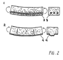
- the central section is only affected by moment - transmission of forces (compression in the upper side of the concrete and traction in the longitudinal reinforcement) does not itself require shear-connection between the reinforcement and the concrete. Failure/insufficient shear capacity has, however, important secondary effects, i.a. concerning control of crevices, vide Fig. 2.
- Fig. 2 shows a segment of conventionally reinforced concrete slabs subjected to pure moment action and having good shear resistance between the reinforcement and the concrete in 1, but with poor shear resistance in 2 with good sound reinforcement 3 in the form of profiled rods a desired behaviour with formation of many very fine crevices is secured.
- reinforcement in the form of profiled sheets 4 the shear resistance in constructions according to the prior art is poor resulting in development of a few very broad and deep crevices.
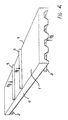
- Fig. 3 shows a part of a slab or beam reinforced at the bottom which breaks due to shear failure between the concrete and the reinforcement.
- Fig. 3 shows the behaviour of the outer section in three stages: 1, 2 and 3.
- the slab, which is supported at the edge 4, is stressed by the force 5.
- stages I a tension fissure 6 is just formed in the concrete. This opens more and more because the force transmission zone C increases to the maximum size - stage 2.
- the zone moves out towards the support resulting finally in failure as illustrated in 3.
- profiled thin sheet/concrete composite articles wherein improvements have been obtained as compared to corresponding plane sheet composites.
- profile sheet/concrete composites as cover elements and for a more or less degree to allow for the utilisation of the reinforcement effect of the sheets in the same manner as with steel reinforcement in ferro-concrete.
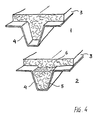
- Fig. 2(a) refers to slabs having trapezoidal form (much resembling the form of the sheet in example 1 of this specification).
- the profile shown in Fig. 2(b) is as in (a), but the sheet parts therein between the trapeziums are not plane but given a further "mini" trapezoidal profile.
- the slab in example 1 showed high carrying capacity, including high shear resistance and very high toughness under extremely high loadings, including concentrated shear stresses.
- the resistance against separation rupture between metal sheets and concrete under tension is small, in particular if it happens by careening after crack initiation.
- the resistance is essentially higher in pure shear.
- This is the main cause for the embodiment of the present invention in the form of profiled sheets as opposed to plane sheets.
- undesired careening failure is strongly counteracted so that contact failure through shear becomes the more dominant rupture form.
- the invention does not differ from the prior art constructions, e.g. the trapezoidal profile sheets of steel and conventional concrete.
- the concrete in the surface 3 is displaced in the direction of the arrow in relation to the profiled sheet 4.
- the lowest part of the concrete 5 is maintained in position in relation to the profiled sheet, since failure has occurred in the concrete article as illustrated with the rupture surface 6.
- Failure near the interfaces can occur by atomic separation between the atoms in the metal surface and the atoms of the composite material, but will in conventional systems also - and very likely predominantly - occur due to failure in the composite material near the interface and not in the interface itself.
- GZc border zone
- the shear resistance can be improved in different ways by different strategies:
- the composite materials are improved very pronounced so that it is possible to utilise conventional profiled steel sheets, which normally would be described as being smooth, in hybrid constructions together with and in intimate contact with "concrete”, showing an extremely high carrying capacity, high toughness and capability to absorb extremely high shear stresses.
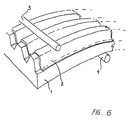
- FIG. 6 shows an arrangement of binding agents proximate a boundary 1, partly conventional cement paste (Fig. 6b), partly binding agents as shown in Fig. 6a, typically used by the invention, with cement particles 2 packed essentially denser than conventionally and with additional 10-25% ultrafine SiO 3 particles deposited in the interspaces between the cement particles.
- the tensile strength of the cement-based composite materials is at least 80 MPa, preferably at least 100 MPa, more preferably at least 150 MPa, yet more preferred at least 200 MPa, most preferred at least 250 MPa, and also in the requirements to the composition of such cement-based binding agents.
- Articles characterised by the binding agents of the composite materials are based on cement like Portland cement and/or Aluminate cement and preferably also ultrafine particles as microsilicate in parts by volume of 1-40%, preferably 5-25% characterised by a high total content of fine particles (e.g. cement + microsilica) of at least 50%, preferably at least 55%, more preferably at least 60%, yet more preferred of at least 65%, most preferred of at least 70% by volume of the total volume of the binding agent.
- fine particles e.g. cement + microsilica
- Fig. 7 illustrates the behaviour of objects - block 1 and substratum 2 - hold together by a glue joint under shear until the joint fails.
- Glue joints are composed of materials having a substantially linear elastic behaviour up to a maximum of stress, a behaviour which is typical for concrete and many composite materials used in connection with the present invention.
- the figure shows the relationship between the shear stress and the displacement.
- the force being transmitted does not correspond to the total area but only to a small fraction corresponding to the extent/area of the size of the active zone. If the active zone is e.g. 20 mm and the "sheet" is 5 m, then the maximum shear force is only about 4 0/00 of the corresponding force on condition that the 5 m large sheet was infinitely rigid.
- Fig. 8 shows the tensile behaviour of typical, conventional concrete 1, strong concrete 2, and 3 the same strong material as 2 imparted rupture-toughness with fibres.
- the relationship between tensile stress and deformation of the crackzone (RZ) is shown.
- the areas below the curves, which represent the work for forming a crack of unit area, are designated the respective energies of rupture G (unit N/m or N/mm).
- the both very strong and very tough material represents a typical composite material according to the present invention.
- the composite materials used in connection with the present invention are imparted very high rupture-toughness which is expressed in terms of that they are imparted high energy of rupture of at least 500 N/m, preferably of at least 1000 N/m, more preferably of at least 2500 N/m, yet more preferred of at least 5000 N/m, still yet more preferred of at least 10,000 N/m, most preferred of at least 20,000 N/m.
- the impart of the high toughness is primarily effected by incorporating fine, strong, rigid fibres, preferably in high concentrations by volume, characterised in that the particle based composite materials contain elongated particles as discrete fibres in concentrations by volume of 0.1 - 1%, and/or 1-2%, and/or 2-5%, and/or 5-10%, and/or 10-20%, and/or 20-60%.
- Composite articles according to the invention based on less rigid binding agents, e.g. plastic.
- a particular aspect of the invention concerns articles wherein the composite materials are based on binding agents of less rigid/frequently very deformable materials such as e.g. binding agents of plastic materials.
- glue joints such materials are very often very suitable to hold together strong rigid components and transmit forces therebetween.
- the materials are also very suitable as matrix material in fine fibre composites for maintaining fine, strong, rigid fibres and transmitting forces between these.
- adhesiveness of the glue materials and their high deformability performance are utilised.
- Soft materials like the most types of plastic are, however, not suitable/inappropriate as materials for large components which have to be incorporated as integrated components together with e.g. steel sheets in strong and rigid hybrid constructions. Here conventional plastic materials are much too yielding.
- plastic particle based composite materials in articles/constructions according to the present invention there is provided the same properties/combinations of properties which make the composite materials appropriate for forming strong, hard, rigid and simultaneously tough bodies with intimate mechanical co-operation with strong sheets, e.g. strong steel sheets. This is obtained with the structure composition described below.
- composition - particles - fibres - hybrid articles.
- the composite materials are composed of binding agents - as for example binding agents of plastic materials wherein strong, rigid particles are incorporated - suitably in a very high concentration by volume.
- cement fineness is often used (referring to cement grains having typically an average grain size of between 5 and 15 ⁇ m, suitably with 5-10% greater than 50 ⁇ m) and "finer than cement” (e.g. referring to conventional micro silica which has a mean particle size of about 0.1 - 0.2 ⁇ m).
- Such materials are used in articles characterised in that the binding agents of the composite materials are based on "fine" particles of cement size - and preferable also ultrafine particles like micro silica in parts by volume of 1-40%, preferably 5-25% - characterised by a total high content of fine particles (e.g. cement + micro silica) of at least 50%, preferably at least 55%, more preferably 60%, yet more preferred of at least 65%, most preferred of at least 70% by volume based on the total volume of the binding agent.
- fine particles of cement size - and preferable also ultrafine particles like micro silica in parts by volume of 1-40%, preferably 5-25% - characterised by a total high content of fine particles (e.g. cement + micro silica) of at least 50%, preferably at least 55%, more preferably 60%, yet more preferred of at least 65%, most preferred of at least 70% by volume based on the total volume of the binding agent.
- Another group of interest of particle-based composite materials for articles according to the invention contains larger particles in high concentration by volume and no or only a small proportion of fine particles.
- “larger” means larger than cement particles, typically particle sizes greater than 100 ⁇ m, however, rarely with particles substantially greater than 10 mm.
- Such interesting composite materials are characterised in that the composite materials contain rigid, strong particles like particles of natural strong rocks such as quartz, diabase and granite preferred to stronger materials like materials of/or rich in alumina, silicon carbide and silicon nitride and/or particles of strong metals like steel or alloys of steel in concentration by volume of at least 30%, preferably at least 40%, more preferably at least 50%, yet more preferred of at least 60%, most preferred of at least 65% by volume based on the total composite material.
- Such composite materials are generally characterised by having a very high concentration by volume of strong, rigid particles referring to the sum of "fine” and larger particles.
- the composite materials also contain elongated fine, strong, rigid components, typically in the form of discrete fibres, threads, fabric or web, and suitable but not always in high concentrations by volume, characterised in that the particle-based composite materials contain elongated particles as discrete fibres in a concentration by volume of 0.1 - 1% and/or 1 - 2% and/or 2 - 5% and/or 5 - 10% and/or 10 - 20% and/or 20-60%.
- the fibres only serve the main object of imparting toughness.
- the proportion by volume of fibres is often so low (e.g. 2% or less) that it has only a marginal effect on the rigidity of the beforehand particle strengthened materials and also has only marginal effect on the amount and the size of the particles which practically can be incorporated into the composite material.
- the fibres have a marked effect both with regard to the contribution to rigidity and with regard to the interaction with particles.
- very interesting composite materials for articles according to the invention having high rigidity and rupture-toughness, characterised by a) very high content of fibres and b) correspondingly low content of "particles", optionally entirely without “particles”.
- the said composite materials are combined with strong, rigid components, e.g. of steel, in the form of slabs imparted profile form.
- the invention is defined by requirements to the properties/combination of properties for composite materials supplemented with requirements as to how such properties are obtained.
- a different way of expressing the invention is by primarily focusing on the approaches made for obtaining the properties and combinations of properties for the composite materials of the hybrid articles which by incorporation into the intimate contact with the profiled sheets forms the articles/constructions of the invention or parts thereof.
- Objects composed of or with particle based composite materials in intimate contact with profiled sheets preferably placed entirely or at least essentially external to the bodies composed of the composite materials, forming the hybrid articles are characterised by that:
- the invention concerns articles wherein composite materials without or with only low content of larger particles are incorporated.
- such composite materials can be composed of a) exclusively cement particles and particles of cement fineness or finer and/or b) also containing slightly larger particles, e.g. particles having sizes from 100 ⁇ m, 250 ⁇ m or up to 1 mm.
- Composite materials of this category is particularly of interest for a) articles/parts which are very thin having e.g. thicknesses of less than 10 mm or less than 5 mm or less than 2 mm, and/or b) articles having a very confined internal structure, e.g. in articles having a very high fibre content such as 2 - 5%, and/or 5 - 10%, and/or between 10% and 20%, and/or between 20% and 60%, and/or higher than 60%.
- Production of components composed of 1) strong cement-based materials, more generally of strong particle-based composite materials in intimate contact with 2) profiled sheets includes:
- Production of composite materials e.g. cement bounded materials, can be effected in accordance with known technology for producing the respective composite materials.
- profiled sheets can be effected according to known technology for the production of such sheets.
- the instant invention concerns processes and methods of joining together components for obtaining intimate contact - and for integral production where e.g. profiled sheets function as form or tool in connection with the production of the composite materials - or where the composite materials conversely function as form or tool in the production of the profiled sheets.
- the invention concerns processes wherein the profiled sheets function as mould sides in processes wherein the composite components are imparted their final shape and final position in intimate contact with the profiled sheets.
- the shaping can be effected with pouring masses which are poured or pressed against the profiled sheets, preferably assisted by mechanical vibration.
- These methods include pouring masses which in fresh condition before solidification are easy flowing to plastic and rigid plastic.
- the methods include compacting pressure of from 10 or 100 Pa which corresponds to the own weight of thin layers of up to 10 or 100 MPa or more as with high pressure compression.
- a particular aspect of the shaping can be effected by smearing or spraying the pouring masses on to the sheets.
- a particular aspect of the invention concerns processes which combine the above methods, e.g. by succeeding a smearing or spraying with pressure compression frequently preferred with oscillating pressure (vibro compression).
- a part of or all the components of the composite material - larger particles, fibres etc. - are preplaced in contact with the profiled sheets whereupon the cavities between these components are filled out by infiltration with liquid binding agent, e.g. assisted by vacuum and/or external pressure.
- intimate contact between the sheet and the fine particles + liquid of the composite pouring mass is first provided and then the coarser parts are applied in contact with the fine particles + liquid.
- this is effected in fresh condition under simultaneous displacement of the said finer particles + liquid up between the coarser particles and components.
- the process can be effected by centrifugation or by external pressure possibly assisted by internal vacuum to secure against inner air accumulations.
- substance composed of finer particles and liquid which penetrate into the confined cavities, e.g. between closely spaced reinforcement or into the roughness in the sheets, is as above first applied followed by a pouring mass containing both fine and coarse particles + liquid which displace the finer particles - liquid system from the areas wherein the coarse particle system can penetrate into and which simultaneously leaves the confined interstices, wherein the coarse particles cannot penetrate, filled with the fine particles - liquid material.
- the pouring masses After having shaped the pouring masses in intimate contact with the sheets the pouring masses solidify, e.g. by hydration in case of cement bound materials, solidification in case of thermoplastic materials, and polymerisation in case of thermosetting plastic materials.
- the solidified materials are separated from the sheet after which adhesive is applied on one or both surfaces whereupon they again are brought in intimate contact and the adhesive solidifies then.
- the adhesive is applied on the surface of the sheets before pouring and hardening, e.g. in the form of a solid film. After the composite materials are placed in contact with the sheet and also in direct contact with the applied solid film the latter is melted by heating and then allowed to solidify and to form the desired adhesive joint.
- the composites and the sheet are prepared separately and are then assembled in intimate contact, e.g. maintained by gluing.
- the composite material article is first produced and then the sheet part is prepared by processes in which the sheet element is brought in intimate contact with the surface of the composite material article.
- Processes of this category can be based on plane sheets which assisted by pressure, optionally vacuum and heating are shaped so as to follow the outer contour of the composite article.
- it may be vacuum shaping of plastic sheets or pressure shaping of sheets of superplastic metal, both processes typically at increased temperature.
- galvanotechnique wherein a metal shell is deposited on the surface of the composite articles in galvanic bathes.
- Other techniques within the scope of the invention are based on other well known coating techniques such as plasma spraying technique and chemical vapour deposition.
- plasma spraying technique and chemical vapour deposition.
- the processes wherein the sheets are first produced it is also possible in the shaping of sheet or shell on the finished composite articles simultaneously to establish the final contact, or the processes are first based on separation of the shaped sheets or shell from the composite articles and then joining them together again in succeeding processes, e.g. by gluing.
- the item is a cover construction in form of a plate having a span of 3 m, simple supported along two edges, designed to absorb even distributed loading.
- the cover plate is composed of (at the bottom) a profiled steel sheet and (at the top) concrete.
- Profile Z-shaped height 50 mm Top and bottom flange 125 mm Body inclination (horizontal/vertical) 25/50 (deviation from vertical) Sheet thickness 1,2 mm Steel quality, yield point 280 N/mm Cover thickness (concrete + steel sheet) 75/125 mm Mean 100 mm Compressive strength of concrete 30 N/mm 2 (cube).
- the zone propagates within which the forces are transmitted, in the following designated the displacement zone.
- Composite slab having high similarity with an actual plate used as example in design of "composite slab” in "Steel Designers' Manual” (composed of concrete and profiled steel sheet, 1.2 mm thick sheet with trapezoidal profile) with respect to concrete, sheet element and sheet thickness.
- the average shear stress is stated.
- Fc shear capacity
- ⁇ utilization of the steel
- the sheet thicknesses should be reduced to 1/4. This would lead to a halving of the shear capacity and a halving of the beforehand extremely small displacement zone. All in all, the use of high steel quality in order to reduce sheet thicknesses will according to conventional technical know-how result in inferior carrying capacity at shear and higher fragility.
- An essential feature of the design strategy which is the basis for design of many articles within the present invention, is regard to the fact that the degree of fragility/toughness does not only depend on the materials, but also on the size of the articles.
- the slab constructions according to the invention are geometric similar with the tested one (cf. example 1) as regards cross section. Simultaneously, the rupture-toughness is adjusted (as in 4) so that the behaviours become similar. Based on the moment capacity (moment of rupture) experimentally found in example 1 the moments of rupture have been calculated from classical beam theory for the larger similar slab constructions and from that in turn calculated the corresponding loadings of rupture.
- Slab construction height mean slab thickness loading at rupture thickness pressure meter water mm mm mm kN/m 2 m according to prior art 125 100 1.2 14,5 1.45 according to the invention 125 53 4.2 204 20.0 236 100 7.9 728 73.0 316 135 10.5 1,306 131.0
- Loading at rupture is expressed in terms of pressure of an evenly distributed loading, partly in kN/m 2 , partly as meter of water column.
- the carrying capacity of the slabs according to prior art is stated in "Steel Designers' Manual” from which they are quoted.
- the slabs of the prior art are designed so as to resist evenly distributed loading of 5/KN m 2 .
- the loading of rupture is 10 KN/m 2 .
- the own weight of 2 KN/m 2 is included therein. Failure occurs by shear rupture along the steel sheet and the concrete. (If shear failure was prevented and slab failure in stead occurred due to plastic yielding at bending, the carrying capacity would have been nearly the double - 28.3 kN/m 2 .
- the invention provides for:
- the material volume of the slab is, as it appears, only 35% greater than that for the reference slab.
- the carrying capacity is about 2 to 6 times higher than one would expect according to conventional technology with the stated increases in material strength and steel sheet thickness, if the well-known fact erroneously was ignored that (due to composite action) the estimated positive effect of stronger concrete for profile sheet/concrete composites will nothing like approximately be obtained. If consideration is paid thereto the figures are yet more surprising to the man skilled in the art concerning the known technology.
- the desired behaviour is secured with the strong, rigid and simultaneously very tough composite materials combined with sheets having profile shape.
- the invention comprises a wide scope of profile embodiments and slab elements and slab thicknesses.
- a group of particularly interesting constructions according to the invention are constructions wherein the profiles are trapeziform - thus not rounded - and here again such wherein the side walls are steep (i.e. the angle between the web and the flange is large, e.g. 44°, optional 60°, optional 70° or optional 80° or 90°).
- Such embodiments increase intimate mechanical co-operation between the sheet profile and the composite material, e.g. so as to counter longitudinal displacement.
- a particular aspect of the invention concerns constructions composed of profiled sheets and said composite materials further reinforced with reinforcement imbedded in the composite materials, typically in the form of bars, threads and wires.
- the reinforcement can be of any material and having arbitrary strength and rigidity.
- the reinforcement is strong having tensile strength of at least 500 MPa, preferably at least 700 MPa, more preferably at least 1000 Mpa, yet more preferably at least 2000 Mpa.
- An example of preferred reinforcement is cold drawn thread of steal having a tensile strength of 1800 MPa, 2000 Mpa, or 2000 - 2500 Mpa.
- the reinforcement can be in the form of separate threads or combined threads forming e.g. cables.
- Particular aspects of the invention concern profiled sheets and composite materials according to the invention reinforced locally or globally.
- a particular aspect of the invention concerns articles profiled in more than one direction.
- a particular aspect of the invention concerns constructions according to the invention provided with extra sheets.
- the extra sheets can serve particular purposes.
- the sheets can e.g. be the inside of rooms (containers, silos etc.) containing materials, substances which are chemical agressive to the other sheet element.
- the extra sheets can i.e. also serve purposes which are related to their form, e.g. smooth surfaces facilitate cleaning and reduce fractional resistance at internal of material movement (liquid movement in pipes, powder movement in pipes and silos etc.).
- the extra sheets can also be part of the bearing construction for strengthening both in longitudinal and cross directions against bending stresses and for increasing the rigidity.
- the joining of the profile sheets and the extra sheets can be effected by reveting, bolting, welding such as e.g. spot welding, glueing and soldering etc..
- the sheets can also be placed in contact with the composite materials.
- Extra sheets placed in contact with the composite materials can serve the same purposes as mentioned previously, and as permanent shuttering/mould side during moulding of the composite materials.
- Extra sheets can have a form deviating from plane or even curved shape.
- a particular aspect of the invention is constructions wherein extra sheets are profiled. The invention.
- the invention concerns sheet formed components. It may be sheet formed components which are plane as will be the case e.g. when the components form plane limitations such as e.g. floors, ceilings or walls in box-shaped constructions as e.g. containers etc.
- the components can also be curved, typically slightly curved as will be the case when the components form limitations which are curved as in tanks, pipes having curved surfaces and shutter constructions.
- Articles according to the invention will typically contain components in the form of sheets. Components according to the invention can also be construction elements such as beams or columns.
- Articles according to the invention can also be objects composed of components previously mentioned and/or construction elements such as pipes, containers, doors, gates, walls, cabins, ceiling constructions, thermo-boxes, refrigerating rooms, heating rooms, security rooms, boilers, cooling towers, chimneys, bridges, top layers for roads etc.
- construction elements such as pipes, containers, doors, gates, walls, cabins, ceiling constructions, thermo-boxes, refrigerating rooms, heating rooms, security rooms, boilers, cooling towers, chimneys, bridges, top layers for roads etc.
- a particular aspect of the invention concerns articles repaired with articles reinforced with the profile sheet composite materials composed according to the invention. It may be e.g. articles as those mentioned in the preceeding paragraph.
- the articles, which are reinforced with the components according to the invention can be of arbitrary solid material as e.g. metal, wood, plast, tile, concrete, gypsum, natural stones, glass and ceramic.
- Special articles according to the invention are articles usable within the machine area such as e.g. motors, pump housings, pumps, moulding tools, moulding machines and especially for use within areas where a low weight/strength ratio is of great importance such as in connection with fast moving/rotating components and within the transport area (aeroplanes, ships, automobiles etc.).
- Special articles according to the invention are wear resisting and/or smooth objects in which the especial friction and wear properties of either the sheet elements or the composite materials, typically are utilized.
- the slab construction is composed of profiled steel sheets in intimate contact with strong, tough, fibre reinforced cement-based composite material. A fragment of the slab cross section is shown in Fig. 10. Steel sheets 1 (1 mm thick) constitute about 13% of the total volume of the slab construction.
- the construction is reinforced with longitudinal and transverse reinforcements placed at the top side 2, 3.
- the transverse reinforcement rods (diameter 3 mm) are placed with a center distance of 150 mm.
- the reinforcement contributes only to stiffen the construction - not to absorb the high tensile stresses at the bottom during bending loading. (There are other preferred articles having also longitudinal reinforcement placed at the bottom, which are still stronger. The purpose was, however, here to test/demonstrate the mode of action of the purely profile reinforced hybrid construction).
- the composite materials 4 was placed dense and homogenous - (with "incorporation" of less than 1% air). As from the recipe and an approximate knowledge of the densities of the components included, the volume proportions of "particles" was calculated (referring to the state prior to the chemical structure formation by the reaction of the cement with the water).
- Cement + micro silica + dispersant 35.7% Sand (calcined bauxite) 46.1% Steel fibres 1.1% Water 17.1%
- Components included in the composite material indicated in % by volume.
- Binder alone Particles (cement + micro silica) 68.0% Liquid 32.0% Composite material. Larger particles (sand - bauxite) 46.0% Steel fibres 1.1 % Binder (particles + liquid) 53.0%
- the energy of rupture of the composite material is estimated from experiences with very closely related materials to be about 3000-4000 N/m (3.0 - 4.0 N/mm).
- Densit-binder supplied from Densit A/S contains about 80% Portland cement (white cement) and about 20% micro silica (50-100 times finer than Portland cement) and a minor amount of dispersive agent in powder form. Strong sand 0-1 mm and 1-2 mm of baked bauxite (Al 2 O 3 rich material). Steel fibres ⁇ 0.4 ⁇ 12 mm, strength 4200 kg/cm 2 . Supplier: Densit A/S Water Tap water. Recipe: Densit binder 8000 g Bauxite 0-1 mm 8000 g Bauxite 1-2 mm 3400 g Steel fibres 0.4 x 12 600 g Water. 1280 g Preparation: Mixing equipment Forced mixing machine. Mixing time Dry mixing 5 min. Wet mixing 8 min. Wet mixing with fibres 5 min. Moulding Soft moulding with vibration. Hardening 1 day and night at 15° - 20°C. 4 Days and nights at 50°C.
- the disposition is shown in Fig. 11.
- the set up is a simple supported slab 1 supported at the ends and at the middle, thus in total 3 supports designated (R1, R2 and R3) for absorbing a vertical line loading P.
- the slab construction was loaded with a line loading P placed centrally on the one section.
- the outer support in the other section was maintained down.
- the loaded half of the slab act as simple supported at the free end and fixed/partly fixed at the middle support.
- the degree of fixing can be determined as the relevant forces were measured (outer loading P and the forces of reaction at all three supports R1, R2 and R3).
- the first comparison made is a comparison between behaviour of the composite articles according to the present example 1 and corresponding sheet articles having the same geometry but made of a homogenous material (e.g. massive quality steel).
- the stresses are calcuated according to the theory of beams (ignoring local forces from the loading).
- the corresponding maximum moments are calculated from the known edge reactions (R1).
- the corresponding maximum tensile stresses (in the bottom side of the slab) are obtained by division with the moment of resistance of the cross section - and by a little extra calculation - also the maximum compressive stresses (in the topside of the slab) and the maximum shear stresses.
- the maximum bending-tensile stress for slabs/beams - actually 319 N/mm 2 - calculated from the analogue elastic slabs are often designated the bending strength (in English terminology Flexural strength).
- the shear stresses refer to the shear stresses acting on the distance between the loading and the free support R1. (They are not the absolute maximae as the shear stresses acting between the loading and the middle support is 10-20% higher - 22 and 10 N/mm 2 , respectively.
- the picture of the stress forces is illustrated in Fig. 12.
- a section of the slab is shown representing 1) a quarter of the width (80 mm) and 2) in the longitudinal direction the part of the slab which is between the loading (marked P) and the free support (marked R1).
- the experiment shows for the article according to the present invention intimate co-operation between the profiled sheet and the strong, rigid, cement-based composite material imparted high rupture-toughness.
- the high compressive strength of the cement-composite (about 250 MPa) allowed use of a very thin layer of composite material (8 mm) and hence a corresponding modest material consumption and low weight.
- Intimate contact This term is used to characterize the contact between the composite materials and the profile sheets. With intimate contact is meant substantially complete atomic contact all over the contact surface as with moulding together, fusing together, gluing together and not as with e.g. bolting together or other mechanical joints. Intimate contact between the specific particle-based materials and the profiled sheets is further elaborated in the patent specification.
- the strength of the composite materials is characterized by claim to the compressive strength with reference to the strength measured by crushing a cylindrical article having a height/diameter ratio of 2 mm and diameter 100 mm, height 200 mm.
- the strength of the composite materials can be determined on special articles prepared of the composite material.
- the strength of the composite material as it is found in the hybrid articles can also be determined by measuring on specimens sawn/bored out or by direct mechanial compressive loadings on the composite material as it is found together with the profiled sheets. By comparison/evaluation of the various determinations of compressive strength it is necessary to establish/prove the relationship to the compressive strength determined with the above cylinder specimens.
- That requirement to strength is related to compressive strength is due to a) the fact that in bending and compression the behaviour at rupture of the composite articles (provided effective co-operation with the profiled sheets) to a high degree is determined by the strength of the materials at compression, b) the compressive strength is often an acceptable property acting as a substitute for other strength characteristics - tension, shear - and c) the compressive strength is relatively simple to determine.
- the rigidity of the composite materials is characterized by the modulus of elasticity referring to the inclination of the stress/strain curve at minor loadings.
- the modulus of elasticity can be determined on particular specimens of the composite material, e.g. cylinders as mentioned in the paragraph concerning compressive strength.
- the modulus of elasticity of the composite materials can also be determined from measurements on the hybrid articles - i.e. with the composite materials in intimate contact with the sheet elements.
- Such determinations can e.g. be performed from determinations of interdependent values of force and deformation of loaded articles or from determination of the resonant frequency of articles under free oscillations. The determinations are then performed on basis of the theory of elasticity applied on the composite article. The determinations presupposes that the behaviour of the profile sheets is known satisfactorily.
- the rupture-toughness of the composite materials is characterized by the energy of rupture G - related to the behaviour at tension.
- the energy of rupture of the composite materials can be determined on particular specimens of the composite material - e.g. beams provided with a cut notch tested at bending, or a tensile specimen provided with notch and tested at tension.
- the energy of rupture of the composite materials can also be determined from measurements on the hybrid articles based on cut out specimens provided with cut notch.
- the reasons for using the energy of rupture in relation to tension for characterizing the rupture-toughness of the composite materials are a) that the behaviour at tension is fundamental for rigid particle-based composite materials at rupture and crack formation; thus, rupture at shear occurs e.g. essentially through failure at tension, b) that the energy of rupture related to tension is a reasonable well defined quantity for rigid, particle-based composite materials, and c) that the energy of rupture related to tension is easy to determine by experiments.
- the invention concerns articles with composite materials in intimate contact with profiled sheets placed preferably entirely or essentially external in relation to the bodies formed of the composite materials.
- the formulation with preferred external placement is motivated in a discrimination between a) preferred articles according to the invention in which the profiled sheets act effectively through their placement in the outer side (closed to the outer side) of the bodies which they form together with the composite materials, and b) articles of composite materials according to the invention but with more centrally embedded sheets.
- the sheet element in example 1 with profiled steel sheets combined with composite materials, placed on the outside of the body formed of the composite materials is typically preferred according to the invention.
- articles according to the invention are obtained as pipes and containers builded up as curved embodiments of sheet articles according to the invention, e.g. as those shown in example 1, both when the composite material constitutes the inner shell and the profile sheet the outer shell, and conversely when the profile sheets are placed internal and the composite shell external. In no cases the profile sheets are completely or partly embedded.
- a limitation for a security box the bearing structure of which is a profiled steel sheet in intimate contact with a strong composite material on the one side thereof will completely satisfy the requirements to: "preferred according to the invention".
- This construction is designed for securing against high mechanical stresses.
- the limitation door/wall/bottom or cealing
- the limitation will typically also have to fulfil a number of other functions which can be provided for with materials placed additionally on the metal surfaces of the hybrid article, i.e. on the outside of the profile sheets.
- it may be fire protection, securing against local attack (e.g. with drills, chisels etc.), hidden by the construction, aesthetical consideration ect.
- Such articles are of course just as preferred as corresponding articles with other materials for the not primary bearing functions and often even more preferred.
- Fig. 13 shows a section in the composite slab.
- the length of the slab is 600 mm.
- 1 Is the composite material
- 2 is the profiled steel sheet
- 3 is a transverse reinforcement, viz. 6 mm diameter cam steel placed each 50 mm
- 4 is a longitudinal top reinforcement, viz. 3 pieces of cam steel, diameter 10 mm.
- the steel reinforcements are fixed so that they did not loosen at vibration.
- the transverse bars are tack welded to the sheet at the ends 5 and the longitudinal bars are tack welded to the transverse reinforcement at the edge 6.
- the composite slabs were subjected to transverse loadings in the disposition shown in Fig. 14.
- Fig. 14 shows the test disposition of the composite slab 1 having the outside dimensions 600 x 230 x 40 mm, placed on the supports 2 and influenced of the vertical line loadings 3.
- the forces on each support and on each loading line are P/2, where P is the total force.
- the disposition is symmetric.
- the distance between the supports is: 500 mm; the distance between the support and the closest point of force attack is: 150 mm.
- the free longitudinal edges 4 were observed through a magnifying glass.
- the slabs were subjected to varying loadings and unloadings at different loading levels varying from 0-25 kN to 7-91 kN.
- the matrix "the concrete" was prepared of materials from the firm Densit A/S. The composition is shown in scheme 1. The properties of the hardened matrix material is shown in scheme 2.
- the profile sheet is of steel of the quality Fe510 B (according to EU 25-72 standards) often designated St. 52-3. Sheet thickness: 2 mm Tensile strength: 580 N/mm 2 . Yield point: 430 N/mm 2 .
- the composition of the "matrix” also called “the concrete", Inducast, is a fine sand concrete with Al 2 O 3 rich sand and a binder based on cement, micro silica and dispersant (in dry powder form). PREPARATION. Specific weight ( ⁇ ) 2950 kg/m 3 Sound velocity (v) 5705 m/sec. Dynamic E-modulus (Edyn) 96.0 GPa Tensile strength (MPa) 225-260 (estimated) Energy of rupture (Nm) 10,000 - 15,000
- the matrix material was prepared in a forced mixing machine.
- the slab is moulded, placed horizontally on a vibration table subjected to vibration of frequency: 50 HZ amplitude.
- the slab is covered with plastic on the top side and stored about 24 hours at 20°C. Then it was wrapped in a wet cloth and tightly fitting plastic and stored about 4 days and nights at 70°C.
- Fig. 15 shows in the form of a sketch a segment of the composite article between the support 3 and the line of attack 4 after shear failure (and suceeding bending failure between the lines of attack). At shear failure the "concrete part" 1 is pushed outward relative to the profile sheet.
- the composite article was designed for experimental purposes with a clear view of elucidating the shear capacity of articles according to the invention, but
- Profile sheet for test composite Profile sheet for composite article Ex. 2 Ex. 1 slope angle 54° 84° Opening relative to a/h height 2.35 0.91 height relative to thickness (h/t) 8 22
- Fig. 16 shows a section of profiled steel sheets used in this example 2 and in the composite article described in example 1, respectively. Indications of the geometry sizes, cf. scheme 4, are marked in the Figures.
- the composite slab showed high inner cohesion without crack formation but with high rigidity, e.g. corresponding to above 70% higher rigidity than for a corresponding article of massive aluminium.
- Shear failure occured at a mean shear stress of between that for profile steel and that for "concrete" about 5 MPa.
- the value is calculated on the basis of the total surface area between force action and support including the two halves outer profile sections where the shear resistance is substantially lower due to lack of squeeze action. Without including the contribution from the outer sections, which are not representative for the slab construction, the force at rupture corresponds to a mean stress of about 7 MPa.
- the profile in the present example 2 is clearly of the former type - "plain profile" - without any form for particular shear arrangements. This means that the shear stress in example 2 of about 5 MPa is of the order 100 times higher than what would usually be allowed according to the known technology.
- the example clearly demonstrates the concept behind the present invention based on a combination of profile sheet plus matrix of high strength, high rigidity and high rupture-toughness, viz. achievement of a very high shear resistance, even with the here used steel sheet of very moderate profiling.
- the aim with the test specimen just was to study boundery cases with composite articles according to the invention having steel sheets of very moderate profiling. That the article showed high shear resistance does not indicate that it is a preferred article of the invention.
- the present invention states more preferred profilings, e.g. with an angle between the web and the flange preferred high, e.g. higher than 60°, preferably higher than 70°, more preferably higher than 80°, most preferably higher than 85°.
- Another aspect of the invention is a composite article according to the invention wherein protection against shear failure and other failure between the profile sheet and the composite material is increased by particular anchoring arrangements.
- This aspect with particular anchoring arrangements is universal, covering both composite articles of the invention with very moderate profiled sheets and articles with very strongly profiled sheets.
- the shear stresses refer to the stresses in a horizontal plane at top of the ribs. Reference is made to the mean values of the shear stresses across the whole area extending from the force transmission to the support (150 mm). The values are shown in scheme 5.
- a 40 mm composite slab according to the invention was subjected to repeated impact actions according to international rules for testing approvement of safe boxes.
- the slab was composed of a profiled, 2 mm thick steel sheet in contact with strong, tough, particle-based composite material - total thickness 40 mm.
- the construction of the composite slab was quite identical with the composite slab shown in example 2, vide i.a. Fig. 13, except that in the slab of the present example there are two longitudinal steel reinforcements for each profil section compared to one in the slab in example 2 and that the instant slab is a little larger, external dimensions of 600 x 540 mm compared to 600 x 240 mm for the slab in example 2.
- Fig. 17 shows a segment of a cross section of the composite slab used in this example.
- 1 Is the composite material
- 2 is the profiled steel sheet, the measures of which are as for the slab of example 2 shown in Fig. 13.
- 3 Is the transverse reinforcement of 6 mm in diameter cam steel per 50 mm.
- 4 Is the longitudinal top reinforcement of 8 mm in diameter cam steel
- 5 is the longitudinal bottom reinforcement of 12 mm in diameter cam steel.
- the main dimensions of the slab are: length 600 mm, width 540 mm, thickness 40 mm and 24 mm (respectively at the profile top and the profile bottom).
- the composite material, the preparation and the hardening were as for the slab in example 2.
- the slab was subjected to the standard test for safe boxes/panels for safe boxes to simulate attack with sledgehammer and blowpipe.
- Test of this type is used to test box-panels for money boxes.
- Those with which the comparison is made are composed of strong cement-based composite material of the same type and substantially the same quality as that used in this example.
- the conventional panels which were selected for comparison purposes, have the same thickness as the maximum thickness of the present profile slab (40 mm) but have 4 times more sheet steel than that according to the example.
- Two slabs has each a thickness of typically 3-5 mm compared to a thickness of 2 mm of the sheet in the present example. (If regard is paid to the profiling of the sheet according to the invention corresponds this to about 2.6 mm 3 steel sheet per mm 2 ). If the reinforcement bars, which often also are found in conventional slabs, are included there is no essential amendment of the fact that the total steel reinforcement still only constitutes about 25-50% of what is conventionally used.
- the conventional slabs in the comparison are, as mentioned, 40 mm thick.
- the slab thickness in the example is in average only 32 mm (with 40 mm and 24 mm, respectively, in the profile top and profile bottom), there is only 80% in average of the slabs with which they are compared.
- the slab is supported along the edges.
- the slab is placed about 1.5 m vertically above the floor in a position well suited for attack with the sledgehammer.
- a marked out area of the slab (120 x 120 mm) on the concrete side was subjected to a number of powerful stresses/impacts with a 3 kg heavy sledgehammer.
- the test was performed by an experienced, strong testperson. Each impact was conducted with what the person described as "with power”.
- the head of the sledgehammer (of steel) had a mass of 3 kg.
- the length of the handle was about 75 cm.
- test destructions occur in the form of one or more of the following mechanisms: 1) local crushing, 2) through-punching (press out of a truncated cone-shaped body), and 3) bending of the composite slab.
- 40 mm thick conventional panels resist typically 10-30 hammer impacts as for articles without the reinforcement bars and 1.5 to 2 times more for articles further provided with reinforcement bars, thus, 20 to max. 60 impacts.
- the preferred safety panels according to the invention do not contain only one profile sheet, but typically two or more profiled sheets.
Landscapes
- Engineering & Computer Science (AREA)
- Architecture (AREA)
- Civil Engineering (AREA)
- Structural Engineering (AREA)
- Curing Cements, Concrete, And Artificial Stone (AREA)
- Laminated Bodies (AREA)
- Diaphragms For Electromechanical Transducers (AREA)
- Preparation Of Compounds By Using Micro-Organisms (AREA)
- Circuits Of Receivers In General (AREA)
Claims (11)
- Ein hybrider Gegenstand aufgebaut von oder mit einem partikelbasierten Kompositmaterialelement für die Konstruktion von hybriden Gegenständen zur Absorbierung von statischen Belastungen, wie beispielsweise an Wand-, Fußboden- und Dachkonstruktionen, oder zur Absorbierung von dynamischen Belastungen, wie beispielsweise an Sicherheitsaufbewahrungseinrichtungen und Fahrspuroberflächen in Flughäfen und an öffentlichen Straßen, der von einem Bindemittel zusammengehalten wird, und eine Profilplatte, die völlig oder im wesentlichen an der Außenseite des Kompositmaterialelementes angebracht ist, wobei das genannte Kompositmaterial 35-70 Volumen% Bindemittel des gesamten Kompositionsvolumens umfasst, wobei das Bindemittel aus 50-70 Volumen% Zement und feinen Partikeln des gesamten Bindemittelvolumens besteht, wobei das Volumen des Kompositmaterials mindestens 50 % des Volumens des hybriden Gegenstandes ausmacht und wobei das genannte Kompositmaterialumfasst, wobei es ein intimer, atomarer Kontakt in der Grenzfläche zwischen dem Kompositmaterialelement und der Profilplatte gibt.a) eine Druckfestigkeit von mindestens 80 MPa,b) ein Dehnungsmodul von mindestens 40.000 MPa, undc) eine Verschiebungsenergie von mindestens 500 N/m
umfasst und das genannte Profilplattemateriald) eine Zugfestigkeit von mindestens 100 MPa - Eine hybride Flachbramme für die Konstruktion von hybriden Gegenständen zur Absorbierung von statischen Belastungen, wie beispielsweise an Wand-, Fußbodenund Dachkonstruktionen, oder zur Absorbierung von dynamischen Belastungen, wie beispielsweise an Sicherheitsaufbewahrungseinrichtungen und Fahrspuroberflächen in Flughäfen und an öffentlichen Straßen, wobei die genannte Flachbramme aus einem partikelbasierten Kompositmaterial im intimen Kontakt mit einem profilierten Plattenelement hergestellt wird, wobei das genannte Kompositmaterial mindestens ein Grundmaterial in der Form von Partikeln des Grundmaterials und einem Bindemittel, das die Partikel des Grundmaterials in eine Position relativ zu einander festhält, umfasst, und das Plattenelement umfasst ein Material, das wie beim profilierten Plattenelement zur Planerstreckung fähig ist, wobei das genannte Profilplattenelement völlig oder im wesentlichen an mindestens einer Außenfläche der genannten hybriden Flachbramme angebracht ist, und wobei das Bindemittel des Kompositmaterials mikrofeine Partikel und feine Partikel enthält, wobei das Volumen der mikrofeinen Partikeln höchstens 40 % des Bindemittelvolumens ausmacht, mehr bevorzugt 5-25 % des Bindemittelvolumens, wobei das Volumen der mikrofeinen Partikeln und der feinen Partikeln zusammen mindestens 50 % des Bindemittelvolumen ausmachen, bevorzugt mindestens 55 % des Bindemittelvolumens, mehr bevorzugt mindestens 60 % des Bindemittelvolumens, noch mehr bevorzugt mindestens 65 % des Bindemittelvolumens, am meisten bevorzugt mindestens 70 % des Bindemittelvolumens, wobei das Volumen des Kompositmaterials mindestens 50 % des hybriden Flachbrammevolumens ausmacht, und wobei das genannte Kompositmaterialumfasst, wobei es ein intimer, atomarer Kontakt in der Grenzfläche zwischen dem Kompositmaterialelement und der Profilplatte gibt.a) eine Druckfestigkeit von mindestens 80 MPa,b) ein Dehnungsmodul von mindestens 40.000 MPa, undc) eine Verschiebungsenergie von mindestens 500 N/m,
umfasst, und das genannte Profilplattemateriald) eine Zugfestigkeit von mindestens 100 Mpa, - Eine hybride Flachbramme gemäß Anspruch 2, dadurch gekennzeichnet, dass das Volumen des Kompositmaterials 55 % des hybriden Flachbrammevolumens ausmacht, bevorzugt 60 % des hybriden Flachbrammevolumens, mehr bevorzugt 65 % des hybriden Flachbrammevolumens, am meistens bevorzugt 70 % des hybriden Flachbrammevolumens.
- Eine hybride Flachbramme gemäß Anspruch 2 oder 3, dadurch gekennzeichnet, dass das Kompositmaterial Fasern enthält, und dass das Volumen der Fasern 0,1-1 % des Kompositmaterialvolumens ausmacht, bevorzugt 1-2 % des Kompositmaterialvolumens, mehr bevorzugt 2-5 % des Kompositmaterialvolumens, am meisten bevorzugt 10-20 % des Kompositmaterialvolumens.
- Eine hybride Flachbramme gemäß jeden der Ansprüchen 2-4, dadurch gekennzeichnet, dass das Kompositmaterial Partikel zur Erhöhung der Kompositmaterialhärtes enthält, vorzugsweise Partikel aus Stein wie Quarz, Diabas und Granit, mehr bevorzugt Partikel aus Kristallen wie Aluminiumoxid, Siliziumcarbid und Siliziumnitrid, am meisten bevorzugt Partikel aus Metallen wie Stahl und Metall-Legierungen, und dass die Partikel zur Erhöhung der Härte mindestens 30 % des Kompositmaterialvolumens ausmachen, bevorzugt mindestens 40 % des Kompositmaterialvolumens, mehr bevorzugt 50 % des Volumens, noch mehr bevorzugt 60 % des Kompositmaterialvolumens, am meisten bevorzugt 65 % des Kompositmaterialvolumens.
- Eine hybride Flachbramme gemäß jeden der Ansprüchen 2-5, dadurch gekennzeichnet, dass das Kompositmaterial Elemente zur Stärkung des Kompositmaterials enthält, und dass die Elemente eine Anzahl von Stangen, eine Anzahl von Fäden, eine Anzahl von Netzwerken und eine Anzahl von Fasern enthalten.
- Eine hybride Flachbramme gemäß jeden der Ansprüchen 2-6, dadurch gekennzeichnet, dass das Bindemittel als mikrofeine Partikel Mikrosilica umfasst, und als feine Partikel Zement, vorzugsweise Portland Zement, alternativ Aluminiumzement, umfasst.
- Eine hybride Flachbramme gemäß jeden der Ansprüchen 2-7, dadurch gekennzeichnet, dass das Plattenelement aus Metall hergestellt ist, und dass das Metall aus der Gruppe, die aus Stahl, Kupfer, Nickel, Titan, Aluminium und Legierungen hiervon besteht, ausgewählt wird.
- Eine hybride Flachbramme gemäß jeden der Ansprüchen 2-8, dadurch gekennzeichnet, dass das Plattenelement aus einen Nicht-Metall hergestellt ist, und dass das Nicht-Metall aus der Gruppe, die aus Keramik und Plastik besteht, ausgewählt wird.
- Eine hybride Flachbramme gemäß jeden der Ansprüchen 2-9, dadurch gekennzeichnet, dass das Profil des Plattenelementes einen trapezförmigen Querschnitt umfasst, dass der trapezförmige Querschnitt Seiten umfasst, die sich in einem Winkel relativ zum Plan der Platte 10°, bevorzugt 20°, mehr bevorzugt 30°, noch mehr bevorzugt 45°, am meisten bevorzugt 60°, erstreckt.
- Ein Verfahren zur Herstellung einer hybriden Flachbramme gemäß jeden der bevorstehenden Ansprüchen, dadurch gekennzeichnet, dass das Kompositmaterial unter Anwendung des Plattenelementes als Form hergestellt wird, alternativ indem das Plattenelement unter Anwendung des Kompositmaterials als Form hergestellt wird.
Applications Claiming Priority (3)
| Application Number | Priority Date | Filing Date | Title |
|---|---|---|---|
| DK23896 | 1996-03-04 | ||
| DK023896A DK23896A (da) | 1996-03-04 | 1996-03-04 | Roc-Kompositsystem |
| PCT/DK1997/000097 WO1997033054A1 (en) | 1996-03-04 | 1997-03-04 | Hybrid plate and method for producing such hybrid plate |
Publications (2)
| Publication Number | Publication Date |
|---|---|
| EP0885336A1 EP0885336A1 (de) | 1998-12-23 |
| EP0885336B1 true EP0885336B1 (de) | 2003-11-19 |
Family
ID=8091303
Family Applications (1)
| Application Number | Title | Priority Date | Filing Date |
|---|---|---|---|
| EP97906092A Expired - Lifetime EP0885336B1 (de) | 1996-03-04 | 1997-03-04 | Hybride platte und herstellungsverfahren |
Country Status (7)
| Country | Link |
|---|---|
| EP (1) | EP0885336B1 (de) |
| JP (1) | JP2000506237A (de) |
| AT (1) | ATE254704T1 (de) |
| AU (1) | AU729947B2 (de) |
| DE (1) | DE69726264D1 (de) |
| DK (1) | DK23896A (de) |
| WO (1) | WO1997033054A1 (de) |
Families Citing this family (5)
| Publication number | Priority date | Publication date | Assignee | Title |
|---|---|---|---|---|
| DK1623080T3 (en) * | 2003-04-14 | 2016-01-25 | Serwin Holding Aps | Sandwich plate-like construction |
| RU2637248C1 (ru) * | 2016-09-06 | 2017-12-01 | Сергей Михайлович Анпилов | Способ возведения большепролётных монолитных железобетонных перекрытий |
| RU2626503C1 (ru) * | 2016-09-14 | 2017-07-28 | Федеральное государственное бюджетное образовательное учреждение высшего образования "Петербургский государственный университет путей сообщения Императора Александра I" | Железобетонная конструкция |
| CN106836601A (zh) * | 2017-02-27 | 2017-06-13 | 天津大学 | 一种带装配式可调节支座负筋的组合板的制作方法 |
| RU2669635C1 (ru) * | 2017-11-15 | 2018-10-12 | Сергей Михайлович Анпилов | Опалубочный элемент сталежелезобетонных перекрытий |
Family Cites Families (5)
| Publication number | Priority date | Publication date | Assignee | Title |
|---|---|---|---|---|
| US1073540A (en) * | 1911-10-11 | 1913-09-16 | Asbestos Protected Metal Co | Building construction. |
| DE1800858A1 (de) * | 1968-10-03 | 1970-05-27 | Siegener Ag Geisweid Eisenkons | Bauplatte,insbesondere zur Herstellung von Gebaeudedecken |
| DE2135128A1 (de) * | 1971-07-09 | 1973-02-01 | Steffens & Noelle Gmbh | Deckenelement |
| GB8429992D0 (en) * | 1984-11-28 | 1985-01-09 | Permanent Formwork Ltd | Fibre reinforced cement |
| DK271386D0 (da) * | 1986-06-09 | 1986-06-09 | Aalborg Portland Cement | Kompakt armeret struktur |
-
1996
- 1996-03-04 DK DK023896A patent/DK23896A/da not_active Application Discontinuation
-
1997
- 1997-03-04 EP EP97906092A patent/EP0885336B1/de not_active Expired - Lifetime
- 1997-03-04 AT AT97906092T patent/ATE254704T1/de not_active IP Right Cessation
- 1997-03-04 WO PCT/DK1997/000097 patent/WO1997033054A1/en not_active Ceased
- 1997-03-04 DE DE69726264T patent/DE69726264D1/de not_active Expired - Lifetime
- 1997-03-04 AU AU20911/97A patent/AU729947B2/en not_active Ceased
- 1997-03-04 JP JP9531367A patent/JP2000506237A/ja active Pending
Also Published As
| Publication number | Publication date |
|---|---|
| DE69726264D1 (de) | 2003-12-24 |
| DK23896A (da) | 1997-09-05 |
| EP0885336A1 (de) | 1998-12-23 |
| AU729947B2 (en) | 2001-02-15 |
| ATE254704T1 (de) | 2003-12-15 |
| AU2091197A (en) | 1997-09-22 |
| JP2000506237A (ja) | 2000-05-23 |
| WO1997033054A1 (en) | 1997-09-12 |
Similar Documents
| Publication | Publication Date | Title |
|---|---|---|
| Said et al. | Using ultra-high performance fiber reinforced concrete in improvement shear strength of reinforced concrete beams | |
| Ismail et al. | Shear behaviour of large-scale rubberized concrete beams reinforced with steel fibres | |
| EP0269715B1 (de) | Kompaktes verstärktes komposit | |
| US4588443A (en) | Shaped article and composite material and method for producing same | |
| Darwin et al. | Splice strength of high relative rib area reinforcing bars | |
| CN102561213B (zh) | 一种结构负弯矩区的钢板-混凝土组合结构加固方法 | |
| Ong et al. | Flexural strengthening of reinforced concrete beams using ferrocement laminates | |
| Saidi et al. | The analysis of the bond strength between natural fiber reinforced polymer (NFRP) sheets and concrete | |
| US20200347598A9 (en) | Impact Resistance of a Cementitious Composite Foam Panel | |
| EP0885336B1 (de) | Hybride platte und herstellungsverfahren | |
| CN101798857A (zh) | 一种异型柱 | |
| US20060014878A1 (en) | Polymer concrete | |
| Donahey et al. | Bond of top-cast bars in bridge decks | |
| US20060220276A1 (en) | Panel particularly for use in platform floors and process for the preparation of said panel | |
| Graybeal | Fatigue response in bridge deck connection composed of field-cast ultra-high-performance concrete | |
| JPH10504359A (ja) | コンクリート製の型枠パネル | |
| Rengarajan | Laboratory testing of shotcrete with fibres of steel, basalt or synthetic materials | |
| Abbas et al. | Structural behavior of reinforced concrete beams having construction joint at different elevation | |
| Duarte et al. | Strengthening of flat slabs with transverse reinforcement | |
| Donahey et al. | Effects of Construction Procedures on Bond in Bridge Decks | |
| Beattie | Behavioral improvements in segmental concrete bridge joints through the use of steel fibers | |
| Ahmadi | End Regions Repair of Prestressed Girders for Restoring the Shear Capacity Using UHPC, FR-SCC, and MALP | |
| Starke et al. | Exploration of UHPC Applications for Montana Bridges | |
| Hollaway et al. | Structural strengthening of concrete beams using unstressed composite plates | |
| Rauscher et al. | Modern composite structures made of high performance materials |
Legal Events
| Date | Code | Title | Description |
|---|---|---|---|
| PUAI | Public reference made under article 153(3) epc to a published international application that has entered the european phase |
Free format text: ORIGINAL CODE: 0009012 |
|
| 17P | Request for examination filed |
Effective date: 19981002 |
|
| AK | Designated contracting states |
Kind code of ref document: A1 Designated state(s): AT BE CH DE DK ES FI FR GB GR IE IT LI NL PT SE |
|
| AX | Request for extension of the european patent |
Free format text: LT PAYMENT 981002;LV PAYMENT 981002;SI PAYMENT 981002 |
|
| 17Q | First examination report despatched |
Effective date: 20000705 |
|
| GRAG | Despatch of communication of intention to grant |
Free format text: ORIGINAL CODE: EPIDOS AGRA |
|
| GRAG | Despatch of communication of intention to grant |
Free format text: ORIGINAL CODE: EPIDOS AGRA |
|
| GRAH | Despatch of communication of intention to grant a patent |
Free format text: ORIGINAL CODE: EPIDOS IGRA |
|
| GRAH | Despatch of communication of intention to grant a patent |
Free format text: ORIGINAL CODE: EPIDOS IGRA |
|
| GRAA | (expected) grant |
Free format text: ORIGINAL CODE: 0009210 |
|
| AK | Designated contracting states |
Kind code of ref document: B1 Designated state(s): AT BE CH DE DK ES FI FR GB GR IE IT LI NL PT SE |
|
| AX | Request for extension of the european patent |
Extension state: LT LV SI |
|
| PG25 | Lapsed in a contracting state [announced via postgrant information from national office to epo] |
Ref country code: NL Free format text: LAPSE BECAUSE OF FAILURE TO SUBMIT A TRANSLATION OF THE DESCRIPTION OR TO PAY THE FEE WITHIN THE PRESCRIBED TIME-LIMIT Effective date: 20031119 Ref country code: LI Free format text: LAPSE BECAUSE OF FAILURE TO SUBMIT A TRANSLATION OF THE DESCRIPTION OR TO PAY THE FEE WITHIN THE PRESCRIBED TIME-LIMIT Effective date: 20031119 Ref country code: IT Free format text: LAPSE BECAUSE OF FAILURE TO SUBMIT A TRANSLATION OF THE DESCRIPTION OR TO PAY THE FEE WITHIN THE PRESCRIBED TIME-LIMIT;WARNING: LAPSES OF ITALIAN PATENTS WITH EFFECTIVE DATE BEFORE 2007 MAY HAVE OCCURRED AT ANY TIME BEFORE 2007. THE CORRECT EFFECTIVE DATE MAY BE DIFFERENT FROM THE ONE RECORDED. Effective date: 20031119 Ref country code: FR Free format text: LAPSE BECAUSE OF FAILURE TO SUBMIT A TRANSLATION OF THE DESCRIPTION OR TO PAY THE FEE WITHIN THE PRESCRIBED TIME-LIMIT Effective date: 20031119 Ref country code: FI Free format text: LAPSE BECAUSE OF FAILURE TO SUBMIT A TRANSLATION OF THE DESCRIPTION OR TO PAY THE FEE WITHIN THE PRESCRIBED TIME-LIMIT Effective date: 20031119 Ref country code: CH Free format text: LAPSE BECAUSE OF FAILURE TO SUBMIT A TRANSLATION OF THE DESCRIPTION OR TO PAY THE FEE WITHIN THE PRESCRIBED TIME-LIMIT Effective date: 20031119 Ref country code: BE Free format text: LAPSE BECAUSE OF FAILURE TO SUBMIT A TRANSLATION OF THE DESCRIPTION OR TO PAY THE FEE WITHIN THE PRESCRIBED TIME-LIMIT Effective date: 20031119 Ref country code: AT Free format text: LAPSE BECAUSE OF FAILURE TO SUBMIT A TRANSLATION OF THE DESCRIPTION OR TO PAY THE FEE WITHIN THE PRESCRIBED TIME-LIMIT Effective date: 20031119 |
|
| REG | Reference to a national code |
Ref country code: GB Ref legal event code: FG4D |
|
| REG | Reference to a national code |
Ref country code: CH Ref legal event code: EP |
|
| REF | Corresponds to: |
Ref document number: 69726264 Country of ref document: DE Date of ref document: 20031224 Kind code of ref document: P |
|
| REG | Reference to a national code |
Ref country code: IE Ref legal event code: FG4D |
|
| PG25 | Lapsed in a contracting state [announced via postgrant information from national office to epo] |
Ref country code: SE Free format text: LAPSE BECAUSE OF FAILURE TO SUBMIT A TRANSLATION OF THE DESCRIPTION OR TO PAY THE FEE WITHIN THE PRESCRIBED TIME-LIMIT Effective date: 20040219 Ref country code: GR Free format text: LAPSE BECAUSE OF FAILURE TO SUBMIT A TRANSLATION OF THE DESCRIPTION OR TO PAY THE FEE WITHIN THE PRESCRIBED TIME-LIMIT Effective date: 20040219 Ref country code: DK Free format text: LAPSE BECAUSE OF FAILURE TO SUBMIT A TRANSLATION OF THE DESCRIPTION OR TO PAY THE FEE WITHIN THE PRESCRIBED TIME-LIMIT Effective date: 20040219 |
|
| PG25 | Lapsed in a contracting state [announced via postgrant information from national office to epo] |
Ref country code: DE Free format text: LAPSE BECAUSE OF FAILURE TO SUBMIT A TRANSLATION OF THE DESCRIPTION OR TO PAY THE FEE WITHIN THE PRESCRIBED TIME-LIMIT Effective date: 20040220 |
|
| PG25 | Lapsed in a contracting state [announced via postgrant information from national office to epo] |
Ref country code: ES Free format text: LAPSE BECAUSE OF FAILURE TO SUBMIT A TRANSLATION OF THE DESCRIPTION OR TO PAY THE FEE WITHIN THE PRESCRIBED TIME-LIMIT Effective date: 20040302 |
|
| PG25 | Lapsed in a contracting state [announced via postgrant information from national office to epo] |
Ref country code: IE Free format text: LAPSE BECAUSE OF NON-PAYMENT OF DUE FEES Effective date: 20040304 Ref country code: GB Free format text: LAPSE BECAUSE OF NON-PAYMENT OF DUE FEES Effective date: 20040304 |
|
| LTIE | Lt: invalidation of european patent or patent extension |
Effective date: 20031119 |
|
| NLV1 | Nl: lapsed or annulled due to failure to fulfill the requirements of art. 29p and 29m of the patents act | ||
| REG | Reference to a national code |
Ref country code: CH Ref legal event code: PL |
|
| PLBE | No opposition filed within time limit |
Free format text: ORIGINAL CODE: 0009261 |
|
| STAA | Information on the status of an ep patent application or granted ep patent |
Free format text: STATUS: NO OPPOSITION FILED WITHIN TIME LIMIT |
|
| GBPC | Gb: european patent ceased through non-payment of renewal fee | ||
| 26N | No opposition filed |
Effective date: 20040820 |
|
| EN | Fr: translation not filed | ||
| REG | Reference to a national code |
Ref country code: IE Ref legal event code: MM4A |
|
| PG25 | Lapsed in a contracting state [announced via postgrant information from national office to epo] |
Ref country code: PT Free format text: LAPSE BECAUSE OF NON-PAYMENT OF DUE FEES Effective date: 20040419 |