EP0884513A2 - Valve combination - Google Patents
Valve combination Download PDFInfo
- Publication number
- EP0884513A2 EP0884513A2 EP19980110498 EP98110498A EP0884513A2 EP 0884513 A2 EP0884513 A2 EP 0884513A2 EP 19980110498 EP19980110498 EP 19980110498 EP 98110498 A EP98110498 A EP 98110498A EP 0884513 A2 EP0884513 A2 EP 0884513A2
- Authority
- EP
- European Patent Office
- Prior art keywords
- valve
- cable head
- pilot
- main valve
- combination according
- Prior art date
- Legal status (The legal status is an assumption and is not a legal conclusion. Google has not performed a legal analysis and makes no representation as to the accuracy of the status listed.)
- Granted
Links
Images

Classifications
-
- F—MECHANICAL ENGINEERING; LIGHTING; HEATING; WEAPONS; BLASTING
- F16—ENGINEERING ELEMENTS AND UNITS; GENERAL MEASURES FOR PRODUCING AND MAINTAINING EFFECTIVE FUNCTIONING OF MACHINES OR INSTALLATIONS; THERMAL INSULATION IN GENERAL
- F16K—VALVES; TAPS; COCKS; ACTUATING-FLOATS; DEVICES FOR VENTING OR AERATING
- F16K31/00—Actuating devices; Operating means; Releasing devices
- F16K31/12—Actuating devices; Operating means; Releasing devices actuated by fluid
- F16K31/36—Actuating devices; Operating means; Releasing devices actuated by fluid in which fluid from the circuit is constantly supplied to the fluid motor
- F16K31/40—Actuating devices; Operating means; Releasing devices actuated by fluid in which fluid from the circuit is constantly supplied to the fluid motor with electrically-actuated member in the discharge of the motor
- F16K31/402—Actuating devices; Operating means; Releasing devices actuated by fluid in which fluid from the circuit is constantly supplied to the fluid motor with electrically-actuated member in the discharge of the motor acting on a diaphragm
-
- Y—GENERAL TAGGING OF NEW TECHNOLOGICAL DEVELOPMENTS; GENERAL TAGGING OF CROSS-SECTIONAL TECHNOLOGIES SPANNING OVER SEVERAL SECTIONS OF THE IPC; TECHNICAL SUBJECTS COVERED BY FORMER USPC CROSS-REFERENCE ART COLLECTIONS [XRACs] AND DIGESTS
- Y10—TECHNICAL SUBJECTS COVERED BY FORMER USPC
- Y10T—TECHNICAL SUBJECTS COVERED BY FORMER US CLASSIFICATION
- Y10T137/00—Fluid handling
- Y10T137/598—With repair, tapping, assembly, or disassembly means
- Y10T137/6184—Removable valve with normally disabled supplemental check valve
- Y10T137/6188—Check valve disabled by normally movable main valve part
- Y10T137/6195—Spring bias
Definitions
- the invention relates to a valve combination with a pilot operated Main valve and a pilot valve.
- valves currently used in sanitary engineering are in general direct acting lifting armature solenoid valves.
- the function of such Valves can build up through deposits of lime, iron oxide or others Substances dissolved in the water between the moving parts, in particular between the core and core guide tube. Especially metallic surfaces are at risk at higher temperatures, such as they occur in hot water or due to the electrical power of the Magnet coils are caused.
- Pilot operated diaphragm valves are less problematic in this regard.
- suitable pilot valves especially small clapper valves, is neither on the fluidic nor on the electrical side a connection technology available, the Sanitary engineering requirements: The connections must easy and reliable to manufacture and without special tools for Maintenance purposes can be solved and yet be mechanically highly stressed.
- the invention provides a valve combination that can be used instead of conventional solenoid valves in sanitary engineering is and on both the fluidic and the electrical Side the simple and fast manufacture of mechanically high allowable and reliable connections.
- the pilot valve in a fluidic with the main valve connectable cable head integrated.
- the cable head which is preferred with an electrical quick connector for an electrical Cable is provided, enables fast on the electrical side and unproblematic cable connection with strain relief.
- On the The cable head enables the fluidic side through a fluidic coupling the quick and easy connection to the main valve, which is preferably designed as a diaphragm valve.
- the fluidic Coupling is preferably with check valves on the side of the Main valve equipped, which is forced when the cable head is attached be opened. The replacement of the pilot valve is therefore possible without removing the main valve and without leakage.
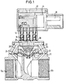
- the valve combination shown in Fig. 1 consists of a as Membrane valve trained main valve 10, a cable head 12 with pilot valve 14 integrated therein, which acts as a small valve is formed, and a fluidic coupling 16, which Main valve 10 connects to the cable head 12.
- the cable head 12 is equipped with an electrical quick connector 18.
- the Main valve 10 has two coaxial media connections 10a, 10b and one laterally arranged valve chamber with a membrane 20 on its outer circumference between a side flange of the main valve 10 and a valve cover 22 is clamped.
- the membrane 20 cooperates an annular sealing seat 24, against which they are by a Compression spring 26 is loaded.
- first channel 28 from the media connection 10a through the valve cover 22 led to a connection flange 30 formed thereon.
- a second channel 32 is from the media connection 10b through the valve cover 22 led to the connecting flange 30.
- a third channel 34 is of that Space behind the membrane 20 led to the connecting flange 30.
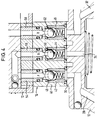
- the clutch 16 shown enlarged in FIG. 4 consists of a on the connecting flange 30 placed intermediate plate 40 with three through connection bores 42, 44, 46 is provided with align the mouths of channels 28, 32 and 34.
- On the website of the connecting flange 30 is each end of the connecting bore 42, 44, 46 sealed to the flange 30 by an annular seal.
- On the Side of the connecting flange 30 in each connection bore 42, 44, 46 Check valve used, the one spring-loaded against an annular seal Ball 48, 50, 52 has.
- On the side of the cable head 12 is in the ends of the connection bores 42, 44, 46 each with a Ring seal provided pipe nipple 54, 56, 58 used sealing.
- the pilot valve 14 is a conventional 3/2-way valve.
- a Such valve has relatively sensitive due to the miniature design electrical leads 62 (Fig. 2). These are inside the Cable head 12 with the electrical quick connector 18 connected and therefore well protected. Since the pilot valve 14 as conventional 3/2-way miniature valve can be formed, superfluous get a detailed description.
- the cable head 12 is detached from the main valve 10 shown.
- the pilot valve 14 can be a direct acting Small valve can be used.
- the fluid ones Connections P A R led out into which the pipe nipples 54, 56, 58 can be used.
- the cable head 12 can also without it Pipe nipple with its fluidic connection surface suitable for one trained counter flange are placed.
- connection configurations are the fluidic coupling 16 the same on both sides. With different Connection configurations between cable head 12 and main valve 10 can be adjusted via the fluidic coupling 16.
- the main valve 10 designed as a diaphragm valve is insensitive against deposits of lime, iron oxide or others in the water dissolved substances.
- the main valve 10 is actuated by means of of the pilot valve 14 via the channels 28, 32 and 34 in a known manner Wise. This results in a low electrical control power also a particularly safe function of the main valve.
- the fluidic coupling 16 with integrated check valves is reduced connecting the pilot valve file 14 to an insertion the pipe nipple into the connection holes, whereupon the screw 60 is tightened to the cable head 12 on the intermediate plate 40 and thus secure at the main valve 10.
- the fluid coupling is mechanical highly resilient.
- the cable head 12 with the Pilot valve 14 can be released from the main valve 10 without Liquid escapes because the check valves close automatically when the pipe nipples come out of the connection holes be pulled out.
- quick connection device 18 enables this easy connection of a cable without tools, at the same time one Strain relief is guaranteed.
Abstract
Description
Die Erfindung betrifft eine Ventilkombination mit einem vorgesteuerten Hauptventil und einem Vorsteuerventil.The invention relates to a valve combination with a pilot operated Main valve and a pilot valve.
Die derzeit in der Sanitärtechnik verwendeten Ventile sind im allgemeinen direktwirkende Hubanker-Magnetventile. Die Funktion solcher Ventile kann durch Ablagerungen von Kalk, Eisenoxid oder anderen im Wasser gelösten Stoffen zwischen den beweglichen Teilen, insbesondere zwischen Kern und Kernführungsrohr, gestört werden. Besonders gefährdet sind metallische Oberflächen bei höheren Temperaturen, wie sie bei Heißwasser auftreten oder durch die elektrische Leistung der Magnetspulen verursacht werden.The valves currently used in sanitary engineering are in general direct acting lifting armature solenoid valves. The function of such Valves can build up through deposits of lime, iron oxide or others Substances dissolved in the water between the moving parts, in particular between the core and core guide tube. Especially metallic surfaces are at risk at higher temperatures, such as they occur in hot water or due to the electrical power of the Magnet coils are caused.
Weniger problematisch sind in dieser Hinsicht vorgesteuerte Membranventile. Für geeignete Vorsteuerventile, insbesondere Klöppel-Kleinventile, steht jedoch weder auf der fluidischen noch auf der elektrischen Seite eine Anschlußtechnik zur Verfügung, die den Forderungen der Sanitärtechnik entspricht: Die Verbindungen müssen leicht und zuverlässig sowie ohne Spezialwerkzeuge herstellbar, für Wartungszwecke lösbar und dennoch mechanisch hochbeanspruchbar sein. Pilot operated diaphragm valves are less problematic in this regard. For suitable pilot valves, especially small clapper valves, is neither on the fluidic nor on the electrical side a connection technology available, the Sanitary engineering requirements: The connections must easy and reliable to manufacture and without special tools for Maintenance purposes can be solved and yet be mechanically highly stressed.
Durch die Erfindung wird eine Ventilkombination geschaffen, die anstelle von herkömmlichen Magnetventilen in der Sanitärtechnik einsetzbar ist und sowohl auf der fluidischen als auch auf der elektrischen Seite die einfache und schnelle Herstellung von mechanisch hoch beanspruchbaren und zuverlässigen Verbindungen ermöglicht. Gemäß der Erfindung ist das Vorsteuerventil in einem fluidisch mit dem Hauptventil verbindbaren Kabelkopf integriert. Der Kabelkopf, der vorzugsweise mit einer elektrischen Schnellanschlußeinrichtung für ein elektrisches Kabel versehen ist, ermöglicht auf der elektrischen Seite den schnellen und unproblematischen Kabelanschluß mit Zugentlastung. Auf der fluidischen Seite ermöglicht der Kabelkopf durch eine fluidische Kupplung die schnelle und unproblematische Verbindung mit dem Hauptventil, das vorzugsweise als Membranventil ausgebildet ist. Die fluidische Kupplung ist vorzugsweise mit Rückschlagventilen auf der Seite des Hauptventils ausgestattet, die beim Aufsetzen des Kabelkopfes zwangsweise geöffnet werden. Der Austausch des Vorsteuerventils ist daher ohne Ausbau des Hauptventils und ohne Leckage möglich.The invention provides a valve combination that can be used instead of conventional solenoid valves in sanitary engineering is and on both the fluidic and the electrical Side the simple and fast manufacture of mechanically high allowable and reliable connections. According to the Invention is the pilot valve in a fluidic with the main valve connectable cable head integrated. The cable head, which is preferred with an electrical quick connector for an electrical Cable is provided, enables fast on the electrical side and unproblematic cable connection with strain relief. On the The cable head enables the fluidic side through a fluidic coupling the quick and easy connection to the main valve, which is preferably designed as a diaphragm valve. The fluidic Coupling is preferably with check valves on the side of the Main valve equipped, which is forced when the cable head is attached be opened. The replacement of the pilot valve is therefore possible without removing the main valve and without leakage.
Weitere Vorteile und Merkmale der Erfindung ergeben sich aus der
folgenden Beschreibung einer bevorzugten Ausführungsform und aus der
Zeichnung, auf die Bezug genommen wird. In der Zeichnung zeigen:
Die in Fig. 1 gezeigte Ventilkombination besteht aus einem als
Membranventil ausgebildeten Hauptventil 10, einem Kabelkopf 12 mit
darin integriertem Vorsteuerventil 14, das als Klöppel-Kleinventil
ausgebildet ist, und einer fluidischen Kupplung 16, die das
Hauptventil 10 mit dem Kabelkopf 12 verbindet. Der Kabelkopf 12 ist
mit einer elektrischen Schnellanschlußeinrichtung 18 ausgestattet. Das
Hauptventil 10 weist zwei koaxiale Medienanschlüsse 10a, 10b und einen
seitlich angeordneten Ventilraum mit einer Membran 20 auf, die an
ihrem Außenumfang zwischen einem seitlichen Flansch des Hauptventils
10 und einem Ventildeckel 22 eingespannt ist. Die Membran 20 wirkt mit
einem ringförmigen Dichtsitz 24 zusammen, gegen den sie durch eine
Druckfeder 26 belastet wird. Für die Vorsteuerung des Hauptventils 10
ist ein erster Kanal 28 vom Medienanschluß 10a durch den Ventildeckel
22 zu einem an diesem gebildeten Anschlußflansch 30 geführt. Ein
zweiter Kanal 32 ist von dem Medienanschluß 10b durch den Ventildeckel
22 zum Anschlußflansch 30 geführt. Ein dritter Kanal 34 ist von dem
Raum hinter der Membran 20 zum Anschlußflansch 30 geführt.The valve combination shown in Fig. 1 consists of a as
Membrane valve trained
Die in Fig. 4 vergrößert gezeigte Kupplung 16 besteht aus einer
auf den Anschlußflansch 30 aufgesetzten Zwischenplatte 40, die mit
drei durchgehenden Anschlußbohrungen 42, 44, 46 versehen ist, die mit
den Mündungsöffnungen der Kanäle 28, 32 und 34 fluchten. Auf der Seite
des Anschlußflansches 30 ist jedes Ende der Anschlußbohrung 42, 44, 46
durch eine Ringdichtung zum Flansch 30 abgedichtet. Ferner ist auf der
Seite des Anschlußflansches 30 in jede Anschlußbohrung 42, 44, 46 ein
Rückschlagventil eingesetzt, das eine gegen eine Ringdichtung federbelastete
Kugel 48, 50, 52 aufweist. Auf der Seite des Kabelkopfes 12
ist in die Enden der Anschlußbohrungen 42, 44, 46 je ein mit einer
Ringdichtung versehener Rohrnippel 54, 56, 58 dichtend eingesetzt.
Diese Rohrnippel 54, 56, 58 sind aus dem Gehäuse des Kabelkopfes 12
herausgeführt. Sie weisen an ihren freien Enden einen Betätigungsstößel
auf, der die zugeordnete Kugel 48, 50 bzw. 52 von ihrer Ringdichtung
abhebt, wenn der Kabelkopf 12 bündig auf die Zwischenplatte
40 aufgesetzt ist. Dieser zwangsweise geöffnete Zustand der Rückschlagventile
ist in Fig. 4 durch gestrichelte Darstellung der Kugeln
48, 50, 52 veranschaulicht. Durch eine in Fig. 3 gezeigte Schraube 60,
die das Gehäuse des Kabelkopfes 12 durchquert, ist dieser auf der
Zwischenplatte 40 befestigt.The
Das Vorsteuerventil 14 ist ein herkömmliches 3/2-Wegeventil. Ein
solches Ventil hat aufgrund der Miniaturbauweise relativ empfindliche
elektrische Anschlußlitzen 62 (Fig. 2). Diese sind im Inneren des
Kabelkopfes 12 mit der elektrischen Schnellanschlußeinrichtung 18
verbunden und daher gut geschützt. Da das Vorsteuerventil 14 als
herkömmliches 3/2-Wege-Miniaturventil ausgebildet sein kann, erübrigt
sich eine detaillierte Beschreibung.The
In Fig. 2 ist der Kabelkopf 12 losgelöst von dem Hauptventil 10
dargestellt. In diesem Zustand kann das Vorsteuerventil 14 als direktwirkendes
Kleinventil verwendet werden. Zu diesem Zweck sind die fluidischen
Anschlüsse P A R herausgeführt, in welche die Rohrnippel 54,
56, 58 eingesetzt werden können. Der Kabelkopf 12 kann auch ohne diese
Rohrnippel mit seiner fluidischen Anschlußfläche auf einen geeignet
ausgebildeten Gegenflansch aufgesetzt werden.2, the
Eei der gezeigten Ausführungsform sind die Anschlußkonfigurationen
der fluidischen Kupplung 16 auf beiden Seiten gleich. Bei unterschiedlichen
Anschlußkonfigurationen zwischen Kabelkopf 12 und Hauptventil
10 kann über die fluidische Kupplung 16 eine Anpassung erfolgen.In the embodiment shown, the connection configurations are
the
Das als Membranventil ausgebildete Hauptventil 10 ist unempfindlich
gegenüber Ablagerungen von Kalk, Eisenoxid oder anderen im Wasser
gelösten Stoffen. Die Betätigung des Hauptventils 10 erfolgt mittels
des Vorsteuerventils 14 über die Kanäle 28, 32 und 34 in bekannter
Weise. Dadurch ergibt sich neben einer geringen elektrischen Ansteuerleistung
auch eine besonders sichere Funktion des Hauptventils. Durch
die fluidische Kupplung 16 mit integrierten Rückschlagventilen reduziert
sich das Anschließen des Vorsteuervenfils 14 auf ein Einsetzen
der Rohrnippel in die Anschlußbohrungen, woraufhin die Schraube 60
angezogen wird, um den Kabelkopf 12 an der Zwischenplatte 40 und somit
am Hauptventil 10 zu sichern. Die fluidische Kupplung ist mechanisch
hoch belastbar. Darüber hinaus kann der Kabelkopf 12 mit dem
Vorsteuerventil 14 vom Hauptventil 10 gelöst werden, ohne daß
Flüssigkeit austritt, denn die Rückschlagventile schließen
automatisch, wenn die Rohrnippel aus den Anschlußbohrungen
herausgezogen werden.The
Die für den elektrischen Anschluß des Vorsteuerventils 14 verwendete
Schnellverbindungseinrichtung 18 schließlich ermöglicht das
leichte Anschließen eines Kabels ohne Werkzeug, wobei zugleich eine
Zugentlastung gewährleistet ist.The used for the electrical connection of the
Claims (10)
Applications Claiming Priority (2)
| Application Number | Priority Date | Filing Date | Title |
|---|---|---|---|
| DE29710023U | 1997-06-09 | ||
| DE29710023 | 1997-06-09 |
Publications (3)
| Publication Number | Publication Date |
|---|---|
| EP0884513A2 true EP0884513A2 (en) | 1998-12-16 |
| EP0884513A3 EP0884513A3 (en) | 1999-03-24 |
| EP0884513B1 EP0884513B1 (en) | 2003-08-20 |
Family
ID=8041368
Family Applications (1)
| Application Number | Title | Priority Date | Filing Date |
|---|---|---|---|
| EP19980110498 Expired - Lifetime EP0884513B1 (en) | 1997-06-09 | 1998-06-09 | Valve combination |
Country Status (4)
| Country | Link |
|---|---|
| US (1) | US5975486A (en) |
| EP (1) | EP0884513B1 (en) |
| AT (1) | ATE247791T1 (en) |
| DE (1) | DE59809324D1 (en) |
Families Citing this family (8)
| Publication number | Priority date | Publication date | Assignee | Title |
|---|---|---|---|---|
| US6394412B2 (en) * | 1993-04-02 | 2002-05-28 | Netafim (A.C.S.) Ltd. | Controlled valve |
| US6328275B1 (en) * | 2000-02-04 | 2001-12-11 | Husco International, Inc. | Bidirectional pilot operated control valve |
| US7156121B2 (en) * | 2003-12-11 | 2007-01-02 | Cox Christopher L | Valve position monitor and method of use |
| US7246787B2 (en) * | 2003-12-19 | 2007-07-24 | Kumar Viraraghavan S | Solenoid valve assembly |
| US7922149B2 (en) * | 2004-07-29 | 2011-04-12 | Siemens Industry Inc. | Damper actuator assembly |
| CN101943188B (en) * | 2010-04-29 | 2013-08-21 | 上海人豪液压技术有限公司 | Compact two-way cartridge valve adopting combined type flange control cover plate |
| JP6209139B2 (en) * | 2014-08-05 | 2017-10-04 | Ckd株式会社 | Pilot operated solenoid valve |
| JP6216738B2 (en) * | 2015-05-26 | 2017-10-18 | Ckd株式会社 | Pilot operated solenoid valve |
Citations (6)
| Publication number | Priority date | Publication date | Assignee | Title |
|---|---|---|---|---|
| DE1161099B (en) * | 1958-12-13 | 1964-01-09 | Concordia Maschinen Und Elek Z | Four-way valve |
| US3145967A (en) * | 1962-04-27 | 1964-08-25 | Lawrence H Gardner | Elastic sleeve valve |
| DE1944163A1 (en) * | 1968-09-05 | 1970-03-12 | Biolog Verfahrenstechnik Ag F | Electromagnetic injector |
| DE3514900A1 (en) * | 1985-04-25 | 1986-11-06 | Krytem GmbH, 4156 Willich | Shut-off element for conduits carrying gases, preferably supercooled gases, in particular a valve |
| WO1997018397A1 (en) * | 1995-11-13 | 1997-05-22 | Wilkerson Corporation | Slow start supply and exhaust valve |
| FR2752901A1 (en) * | 1996-08-28 | 1998-03-06 | Bayard | Electro=control valve for water distribution systems |
Family Cites Families (13)
| Publication number | Priority date | Publication date | Assignee | Title |
|---|---|---|---|---|
| US2412490A (en) * | 1944-04-26 | 1946-12-10 | Gen Controls Co | Fluid control valve |
| US2893680A (en) * | 1955-01-10 | 1959-07-07 | Phillips Petroleum Co | Valve |
| DE1085000B (en) * | 1957-06-18 | 1960-07-07 | Concordia Maschinen U Elek Zit | Shut-off valve for changing flow directions |
| US3265352A (en) * | 1963-09-25 | 1966-08-09 | Westinghouse Air Brake Co | Valve assembly with liquid-seal electrical plug connection |
| US3477466A (en) * | 1967-04-03 | 1969-11-11 | Lewis D Sturm | Elevator fluid control valve mechanism |
| US3913884A (en) * | 1973-07-09 | 1975-10-21 | Automatic Switch Co | Variable bleed valve |
| NO140919C (en) * | 1978-04-17 | 1979-12-12 | Helge Dybvig | FUEL SYSTEM DEVICE, ESPECIALLY FOR BOATS |
| JPS6241482A (en) * | 1985-08-15 | 1987-02-23 | Smc Corp | Pilot type dual-port solenoid valve |
| DE3717341A1 (en) * | 1987-05-22 | 1988-12-08 | Daimler Benz Ag | VALVE ARRANGEMENT WITH MAIN SWITCHING VALVE AND PILOT VALVE |
| US4981280A (en) * | 1989-04-27 | 1991-01-01 | The Aro Corporation | Solenoid actuated fluid valve |
| US5074524A (en) * | 1990-10-16 | 1991-12-24 | Bridge Products, Inc. | Quick disconnect coupler |
| CN1026256C (en) * | 1991-07-02 | 1994-10-19 | 浙江瑞安永久机电研究所 | Separative self controlling valve |
| US5794651A (en) * | 1996-03-13 | 1998-08-18 | General Hydraulics Corporation | Valve adaptor cap |
-
1998
- 1998-06-09 US US09/093,792 patent/US5975486A/en not_active Expired - Fee Related
- 1998-06-09 AT AT98110498T patent/ATE247791T1/en not_active IP Right Cessation
- 1998-06-09 DE DE59809324T patent/DE59809324D1/en not_active Expired - Fee Related
- 1998-06-09 EP EP19980110498 patent/EP0884513B1/en not_active Expired - Lifetime
Patent Citations (6)
| Publication number | Priority date | Publication date | Assignee | Title |
|---|---|---|---|---|
| DE1161099B (en) * | 1958-12-13 | 1964-01-09 | Concordia Maschinen Und Elek Z | Four-way valve |
| US3145967A (en) * | 1962-04-27 | 1964-08-25 | Lawrence H Gardner | Elastic sleeve valve |
| DE1944163A1 (en) * | 1968-09-05 | 1970-03-12 | Biolog Verfahrenstechnik Ag F | Electromagnetic injector |
| DE3514900A1 (en) * | 1985-04-25 | 1986-11-06 | Krytem GmbH, 4156 Willich | Shut-off element for conduits carrying gases, preferably supercooled gases, in particular a valve |
| WO1997018397A1 (en) * | 1995-11-13 | 1997-05-22 | Wilkerson Corporation | Slow start supply and exhaust valve |
| FR2752901A1 (en) * | 1996-08-28 | 1998-03-06 | Bayard | Electro=control valve for water distribution systems |
Also Published As
| Publication number | Publication date |
|---|---|
| ATE247791T1 (en) | 2003-09-15 |
| EP0884513B1 (en) | 2003-08-20 |
| US5975486A (en) | 1999-11-02 |
| EP0884513A3 (en) | 1999-03-24 |
| DE59809324D1 (en) | 2003-09-25 |
Similar Documents
| Publication | Publication Date | Title |
|---|---|---|
| DE4101001C2 (en) | Coupling device with pressure reducing elements | |
| EP0271765B1 (en) | Self fluid controlled valve releasable by an especially solenoid controlled pilot valve | |
| AT400748B (en) | CARTRIDGE VALVE | |
| DE3829242C2 (en) | Self-flushing hydraulic clutch and method for flushing a hydraulic line with such a hydraulic clutch | |
| EP0038470B1 (en) | Sticking connection elements for an aquarium pipe under pressure | |
| EP0038056A2 (en) | Quick-acting coupling for hoses or the like | |
| DE2061821A1 (en) | Device for connecting hydraulic devices | |
| EP1357325A2 (en) | Quick-acting coupling | |
| DE10018364A1 (en) | Hydraulic underwater coupling with extended probe section | |
| DE10123498B4 (en) | Hydraulic underwater coupling part with primary and secondary valves | |
| EP0884513B1 (en) | Valve combination | |
| DE102014106940B4 (en) | Electromagnetically operated high-pressure gas valve | |
| WO2001091244A1 (en) | Pressure compensated plug connector | |
| WO2006136354A1 (en) | Venting screw comprising a check valve | |
| EP0754899B1 (en) | Ball-valve with quick-acting connector | |
| EP0005197A1 (en) | Safety device in case of rupturing of a hose between a pressurized conduit and the supply pipe of an apparatus | |
| DE10332332B4 (en) | Automatically decoupled in an emergency fluid coupling | |
| WO1982001929A1 (en) | Coupling device for connecting two conduit sections for fluid materials | |
| DE1650143A1 (en) | Fluid coupling | |
| DE202011004778U1 (en) | Coupling part of a pressure medium line coupling | |
| EP0090941B1 (en) | Hose rupture safety device for fluids, especially for gas plants | |
| DD253751A5 (en) | FERKELTRAENKEBECKEN | |
| DE3044885A1 (en) | Hydraulic coupling between tractor and implement - has two spring loaded pressure relief valves in series to discharge pressure in line | |
| WO1989005382A1 (en) | Nonreturn valve, in particular for incorporation in drinking water pipes | |
| DE2505217C3 (en) | Shut-off valve |
Legal Events
| Date | Code | Title | Description |
|---|---|---|---|
| PUAI | Public reference made under article 153(3) epc to a published international application that has entered the european phase |
Free format text: ORIGINAL CODE: 0009012 |
|
| AK | Designated contracting states |
Kind code of ref document: A2 Designated state(s): AT CH DE FR GB IT LI |
|
| AX | Request for extension of the european patent |
Free format text: AL;LT;LV;MK;RO;SI |
|
| PUAL | Search report despatched |
Free format text: ORIGINAL CODE: 0009013 |
|
| AK | Designated contracting states |
Kind code of ref document: A3 Designated state(s): AT BE CH CY DE DK ES FI FR GB GR IE IT LI LU MC NL PT SE |
|
| AX | Request for extension of the european patent |
Free format text: AL;LT;LV;MK;RO;SI |
|
| 17P | Request for examination filed |
Effective date: 19990506 |
|
| AKX | Designation fees paid |
Free format text: AT CH DE FR GB IT LI |
|
| 17Q | First examination report despatched |
Effective date: 20020502 |
|
| GRAH | Despatch of communication of intention to grant a patent |
Free format text: ORIGINAL CODE: EPIDOS IGRA |
|
| GRAS | Grant fee paid |
Free format text: ORIGINAL CODE: EPIDOSNIGR3 |
|
| GRAA | (expected) grant |
Free format text: ORIGINAL CODE: 0009210 |
|
| AK | Designated contracting states |
Designated state(s): AT CH DE FR GB IT LI |
|
| REG | Reference to a national code |
Ref country code: GB Ref legal event code: FG4D Free format text: NOT ENGLISH |
|
| REG | Reference to a national code |
Ref country code: CH Ref legal event code: NV Representative=s name: TROESCH SCHEIDEGGER WERNER AG Ref country code: CH Ref legal event code: EP |
|
| REF | Corresponds to: |
Ref document number: 59809324 Country of ref document: DE Date of ref document: 20030925 Kind code of ref document: P |
|
| GBT | Gb: translation of ep patent filed (gb section 77(6)(a)/1977) |
Effective date: 20031119 |
|
| ET | Fr: translation filed | ||
| PGFP | Annual fee paid to national office [announced via postgrant information from national office to epo] |
Ref country code: DE Payment date: 20040602 Year of fee payment: 7 |
|
| PGFP | Annual fee paid to national office [announced via postgrant information from national office to epo] |
Ref country code: FR Payment date: 20040608 Year of fee payment: 7 |
|
| PGFP | Annual fee paid to national office [announced via postgrant information from national office to epo] |
Ref country code: GB Payment date: 20040609 Year of fee payment: 7 |
|
| PGFP | Annual fee paid to national office [announced via postgrant information from national office to epo] |
Ref country code: AT Payment date: 20040611 Year of fee payment: 7 |
|
| PGFP | Annual fee paid to national office [announced via postgrant information from national office to epo] |
Ref country code: CH Payment date: 20040616 Year of fee payment: 7 |
|
| PLBE | No opposition filed within time limit |
Free format text: ORIGINAL CODE: 0009261 |
|
| STAA | Information on the status of an ep patent application or granted ep patent |
Free format text: STATUS: NO OPPOSITION FILED WITHIN TIME LIMIT |
|
| 26N | No opposition filed |
Effective date: 20040524 |
|
| PG25 | Lapsed in a contracting state [announced via postgrant information from national office to epo] |
Ref country code: IT Free format text: LAPSE BECAUSE OF NON-PAYMENT OF DUE FEES Effective date: 20050609 Ref country code: AT Free format text: LAPSE BECAUSE OF NON-PAYMENT OF DUE FEES Effective date: 20050609 |
|
| PG25 | Lapsed in a contracting state [announced via postgrant information from national office to epo] |
Ref country code: LI Free format text: LAPSE BECAUSE OF NON-PAYMENT OF DUE FEES Effective date: 20050630 Ref country code: CH Free format text: LAPSE BECAUSE OF NON-PAYMENT OF DUE FEES Effective date: 20050630 |
|
| PG25 | Lapsed in a contracting state [announced via postgrant information from national office to epo] |
Ref country code: DE Free format text: LAPSE BECAUSE OF NON-PAYMENT OF DUE FEES Effective date: 20060103 |
|
| REG | Reference to a national code |
Ref country code: CH Ref legal event code: PL |
|
| PG25 | Lapsed in a contracting state [announced via postgrant information from national office to epo] |
Ref country code: FR Free format text: LAPSE BECAUSE OF NON-PAYMENT OF DUE FEES Effective date: 20060228 |
|
| GBPC | Gb: european patent ceased through non-payment of renewal fee |
Effective date: 20050609 |
|
| REG | Reference to a national code |
Ref country code: FR Ref legal event code: ST Effective date: 20060228 |