EP0884474A2 - Kommunikationssteuereinrichtung - Google Patents
Kommunikationssteuereinrichtung Download PDFInfo
- Publication number
- EP0884474A2 EP0884474A2 EP98304610A EP98304610A EP0884474A2 EP 0884474 A2 EP0884474 A2 EP 0884474A2 EP 98304610 A EP98304610 A EP 98304610A EP 98304610 A EP98304610 A EP 98304610A EP 0884474 A2 EP0884474 A2 EP 0884474A2
- Authority
- EP
- European Patent Office
- Prior art keywords
- time
- communication
- state change
- section
- transmission
- Prior art date
- Legal status (The legal status is an assumption and is not a legal conclusion. Google has not performed a legal analysis and makes no representation as to the accuracy of the status listed.)
- Granted
Links
- 230000006854 communication Effects 0.000 title claims abstract description 125
- 238000004891 communication Methods 0.000 title claims abstract description 125
- 230000005540 biological transmission Effects 0.000 claims abstract description 108
- 238000001514 detection method Methods 0.000 claims abstract description 20
- 230000002457 bidirectional effect Effects 0.000 claims description 12
- 238000012544 monitoring process Methods 0.000 claims description 4
- 230000007175 bidirectional communication Effects 0.000 claims description 3
- 230000008054 signal transmission Effects 0.000 description 10
- 238000010586 diagram Methods 0.000 description 5
- 238000006243 chemical reaction Methods 0.000 description 3
- 238000006073 displacement reaction Methods 0.000 description 3
- 238000012790 confirmation Methods 0.000 description 2
- 230000003247 decreasing effect Effects 0.000 description 2
- 239000000446 fuel Substances 0.000 description 2
- 238000012545 processing Methods 0.000 description 2
- 230000001629 suppression Effects 0.000 description 2
- 238000012937 correction Methods 0.000 description 1
- 230000003111 delayed effect Effects 0.000 description 1
- 230000000977 initiatory effect Effects 0.000 description 1
- 238000002347 injection Methods 0.000 description 1
- 239000007924 injection Substances 0.000 description 1
- 238000012986 modification Methods 0.000 description 1
- 230000004048 modification Effects 0.000 description 1
- 238000012163 sequencing technique Methods 0.000 description 1
- 238000012795 verification Methods 0.000 description 1
Images


Classifications
-
- F—MECHANICAL ENGINEERING; LIGHTING; HEATING; WEAPONS; BLASTING
- F02—COMBUSTION ENGINES; HOT-GAS OR COMBUSTION-PRODUCT ENGINE PLANTS
- F02P—IGNITION, OTHER THAN COMPRESSION IGNITION, FOR INTERNAL-COMBUSTION ENGINES; TESTING OF IGNITION TIMING IN COMPRESSION-IGNITION ENGINES
- F02P5/00—Advancing or retarding ignition; Control therefor
- F02P5/04—Advancing or retarding ignition; Control therefor automatically, as a function of the working conditions of the engine or vehicle or of the atmospheric conditions
- F02P5/145—Advancing or retarding ignition; Control therefor automatically, as a function of the working conditions of the engine or vehicle or of the atmospheric conditions using electrical means
- F02P5/15—Digital data processing
- F02P5/1502—Digital data processing using one central computing unit
-
- B—PERFORMING OPERATIONS; TRANSPORTING
- B60—VEHICLES IN GENERAL
- B60R—VEHICLES, VEHICLE FITTINGS, OR VEHICLE PARTS, NOT OTHERWISE PROVIDED FOR
- B60R16/00—Electric or fluid circuits specially adapted for vehicles and not otherwise provided for; Arrangement of elements of electric or fluid circuits specially adapted for vehicles and not otherwise provided for
- B60R16/02—Electric or fluid circuits specially adapted for vehicles and not otherwise provided for; Arrangement of elements of electric or fluid circuits specially adapted for vehicles and not otherwise provided for electric constitutive elements
- B60R16/03—Electric or fluid circuits specially adapted for vehicles and not otherwise provided for; Arrangement of elements of electric or fluid circuits specially adapted for vehicles and not otherwise provided for electric constitutive elements for supply of electrical power to vehicle subsystems or for
- B60R16/0315—Electric or fluid circuits specially adapted for vehicles and not otherwise provided for; Arrangement of elements of electric or fluid circuits specially adapted for vehicles and not otherwise provided for electric constitutive elements for supply of electrical power to vehicle subsystems or for using multiplexing techniques
-
- Y—GENERAL TAGGING OF NEW TECHNOLOGICAL DEVELOPMENTS; GENERAL TAGGING OF CROSS-SECTIONAL TECHNOLOGIES SPANNING OVER SEVERAL SECTIONS OF THE IPC; TECHNICAL SUBJECTS COVERED BY FORMER USPC CROSS-REFERENCE ART COLLECTIONS [XRACs] AND DIGESTS
- Y02—TECHNOLOGIES OR APPLICATIONS FOR MITIGATION OR ADAPTATION AGAINST CLIMATE CHANGE
- Y02T—CLIMATE CHANGE MITIGATION TECHNOLOGIES RELATED TO TRANSPORTATION
- Y02T10/00—Road transport of goods or passengers
- Y02T10/10—Internal combustion engine [ICE] based vehicles
- Y02T10/40—Engine management systems
Definitions
- This invention relates to a communication control device having a transmitting section for serially transmitting two or more input signals, e.g., parallel input control signals, to a controlled section.
- Various communication control devices are known which allow for communication between units over a communication line.
- the known communication control devices have more or less the functions as illustrated in block diagram in Fig. 10 hereof.
- the illustrated communication control device 100 comprises a controlling section 110, a transmitting section 120, a serial transmission line 130, a receiving section 140, and a controlled section 150.
- the controlling section 110 supplies a plurality of control signals to a plurality of output ports (0 to N) for controlling the action of the controlled section 150.
- the control signals supplied to the output ports contain information for controlling a plurality of controlled objects not shown but provided in the controlled section 150.
- the controlling section 110 outputs, for example, to a first output port a signal instructing a first one of the controlled objects to perform an ON/OFF operation, to a second output port a signal instructing a second one of the controlled objects to perform an ON/OFF operation, to third and fourth output ports signals instructing a third one of the controlled objects to hold four different kinds of operational conditions, and to other output ports values for controlling other controlled objects.
- the transmitting section 120 constantly monitors the state of the control signals output from the output ports of the controlling section 110. When a change whatsoever arises in an output state of any one of the output ports, the transmitting section 120 latches the outputs from all of the output ports, parallel-serial converts the latched outputs (into serial bit signals) and supplies the converted signals to the serial transmission line 130 at a proset data transmission speed.
- the transmitting section 120 When a change arises in an output state of any output port during an idle state (communication standby state) in which the transmitting section 120 is sending out no serial signals, the transmitting section 120 immediately latches the state of the output port and sends out serial signals.
- the transmitting section 120 latches the state of the output port and sends out serial signals after transmission of the serial signals being sent out is finished.
- the receiving section 140 receives the serially transmitted states of all of the output ports and transmits control signals, resulted from serial-parallel conversion of the received states, to the controlled section 150 in parallel.
- the states of the output ports of the controlling section 110 are transferred to the controlled section 150 in this manner.
- the controlled section 150 controls the operation of the controlled objects therein.
- the state of the output ports of the controlling section 110 can be transmitted to the controlled section 150 over a single transmission line connected therebetween.
- controlling section 110 comprises an electronic control unit (ECU) for the ignition spark control and fuel injection
- controlled section 150 comprises an electronic ignition system and a fuel injector.
- ECU electronice control unit
- controlling section 110 outputs an ignition control signal in such a manner as to achieve the target ignition timing, the actual ignition occurring at the controlled section 150 is retarded by at least the time T required for the serial communication of the ignition control signal between the controlling section 110 and the controlled section 150.
- the conventional communication control device 100 is arranged so that it outputs control signals intolerable of a delay of the time required for the serial communication, earlier than the target ignition timing (point) set at the controlling section 110 by the time required for the serial communication of the control signals.
- Fig. 11 illustrates the operation of the conventional communication control device.
- the controlling section 110 Based on input signals from, e.g., a crankshaft position sensor (not shown), the controlling section 110 calculates a rotational speed and angle of a crankshaft as well as a target ignition timing. As shown in (a) of Fig. 11, the controlling section 110 outputs to a predetermined output port an ignition control signal earlier by the time T required for the serail communication than the target ignition point (delay correction).
- the transmitting section 120 latches the output states of all of the output ports and serially transmits the latched state of each output port. Since the data length and data transmission rate is preset, the communication time T shown in (b) of Fig. 11 is constant.
- the receiving section 140 receives a series of data sent out from the transmitting section 120, serial-parallel converts the serial signals and outputs the converted signals.
- an ignition output corresponding to the ignition control signal is supplied from the receiving section 140 to the controlled section 150, as shown in (c) of Fig. 11, thereby effecting the ignition spark at the target ignition point.
- the controlling section 110 outputs an ignition control signal the time T earlier than the target ignition point (timing).
- the transmitting section 120 detects a change in the state of the separate control signal and commences serial communication.
- the maximum value of the time of delay from the target ignition point is equal to the communication time T required for the serial communication.
- the conventional communication control device 100 there will be a delay of at most the communication time T before the state of a new output port of the controlling section 110 is transmitted to the controlled section 150.
- the time lag from the output of a control signal by the controlling section 110 to the arrival of the same signal at the controlled section 150 is 0 to the communication time T.
- a communication control device which comprises a state change detecting section for monitoring a state change in parallel input control signals and outputting a transmission control instruction upon detection of the state change in any one of the control signals, a transmitting section for transmitting, in accordance with the transmission control instruction from the state change detecting section, the control signals at the time of receipt of the instruction to a serial transmission line serially, and a controlled section for receiving the serial signals from the serial transmission line to thereby operate a controlled object therein, wherein a standby time is provided between the time of detection of the state change in the control signals and the time of commencement of transmission of the serial signals by the transmitting section, and wherein the state change detecting section outputs, in relation to the control signals having a desired time to actuate the controlled object, the transmission control instruction a communication time (T) plus the standby time (t) earlier than the desired time.
- the standby time may be provided in the state change detecting section or the transmitting section.
- the state change detecting section may be arranged to wait for the standby time to lapse for outputting the transmission control instruction, thereby enabling the transmitting section to immediately commence the transmission of the serial signals.
- the transmitting section may be arranged to wait for the standby time to lapse for outputting the serials signals, thereby enabling the state change detecting section to output the transmission control instruction in accordance with a control signal state change.
- a transmission operation in accordance with the control signal state change occurred earlier than the time of detection is continuing, a transmission operation in accordance with the state change in the any one control signal is caused to start upon completion of the continuing transmission operation.
- the standby time is substantially equal to a half of the communication time.
- the standby time is longer than a half of the communication time and shorter than the communication time.
- a communication control device which comprises a state change detecting section for monitoring a state change in parallel input control signals and outputting a transmission control instruction upon detection of the state change in any one of the control signals, a transmitting section for transmitting, in accordance with the transmission control instruction from the state change detecting section, the control signals at the time of receipt of the instruction to a serial transmission line serially, and a controlled section for receiving the serial signals from the serial transmission line to thereby operate a controlled object therein, wherein when a state change is detected in one of the control signals having a desired time to actuate a controlled object, a deterrent time is provided for suppressing a transmission operation in accordance with a state change in another control signal occurred earlier than the desired time, and wherein the deterrent time is longer than a communication time (T) and shorter than two times the communication time.
- T communication time
- the deterrent time may be provided in the state change detecting section or the transmitting section,
- a communication control device 1 in accordance with the present invention comprises a controlling section 10, a transmitting section 20, a state change detecting section 21, a serial transmission line 30, a receiving section 40 and a controlled section 50.
- the controlling section 10 Based on various input signals, the controlling section 10 outputs to output ports (0 - N) control signals for controlling the operation of the controlled section 50.
- the control signals fed to the output ports comprise control information for controlled objects not shown but provided in the controlled section 50.
- the controlling section 10 outputs to a first output port a signal instructing a first controlled object to perform an ON/OFF operation, to a second output port a signal instructing a second controlled object to perform an ON/OFF operation, to third and fourth output ports signals instructing a third controlled object to hold four different kinds of operational conditions, and to other output ports values for controlling other controlled objects.
- the state change detecting section 21 monitors the state of at least one of parallel input control signals and outputs a transmission control instruction 21b to the transmitting section 20 when it detects a change in the state of any one of the control signals.
- a standby time “t" running from the time of detection of the state change of the control signal to the time at which the transmitting section 20 commences transmission of a serial signal is set by the state change detecting section 21 or the transmitting section 20.
- the controlling section 10 Upon outputting a control signal for actuating a controlled object at a desired time, the controlling section 10 outputs the control signal the communication time T plus the standby time t (T + t) earlier than the desired time.
- the state change detecting section 21 Upon detection of a change in the output state of an output port while an idle/busy signal 23a from a transmission control circuit 23 indicates an idle state, the state change detecting section 21 first outputs a latch signal 21a after lapsing of the standby time t from the time of detection of an initial change and then a transmission control instruction 21b. Upon detection of a change in the state of an output port while the idle/busy signal 23a indicates a busy state (being in serial communication), the state change detecting section 21 outputs the latch signal 21a upon turning of the idle/busy signal 23a to an idle state (i.e., upon termination of the communication) and then the transmission control instruction 21b.
- the transmission section 20 has a data latch circuit 22 and the transmission control circuit 23.
- the data latch circuit 22 latches the control signals then output to the output ports 0 - N of the controlling section 10.
- the latched control signals are fed to the transmission control circuit 23.
- the transmission control circuit 23 When fed with a transmission control instruction 21b from the state change detecting section 21, the transmission control circuit 23 converts the control signals latched by the data latch circuit 22 into serial bit signals, adds to the head and tail of the serial bit signals information such as a start bit and a stop bit for providing character synchronization, and transmits the resulted signals to the serial transmission line 30.
- the transmission control circuit 23 In an idle state wherein no serial communication is carried out, the transmission control circuit 23 outputs an idle/busy signal 23a indicating an idle state while it outputs an idle/busy signal 23a indicating a busy state wherein serial communication is being carried out.
- the serial transmission line 30 is comprised of a single communication line.
- the receiving section 40 receives the serially transmitted signals and parallel outputs to the controlled section 50 the control signals obtained by serial-parallel conversion of the received signals.
- the state of an output port of the controlling section 10 is thus transmitted to the controlled section 50.
- the controlled section 50 controls the operation of the controlled objects therein.
- Figs. 2 to 4 illustrate the operations of the described communication control device.
- an ignition control signal is exemplified as a control signal for the control of a controlled object in which a delay of operation is undesirable.
- Fig. 2 shows a case wherein no competition occurs between the ignition control signal and another control signal.
- the controlling section 10 outputs an ignition control signal the communication time T plus the standby time t (T + t or cT) earlier than the target ignition point (timing).
- the ignition control signal is output one and a half times (1.5T) earlier than the target ignition point (timing).
- the transmitting section 20 At the time of output of the ignition control signal, the transmitting section 20 is in an idle state. Where no transmission control instructions are output to the transmitting section 20 in a time period from the time of output of the ignition control signal to a time point earlier by the standby time t, the transmitting section 20 latches the state of the output ports and commences the relevant serial transmission upon lapsing of the standby time t from the time of output of the ignition control signal.
- the ignition output is supplied from the receiving section 40 to the controlled section 50.
- the ignition output is thus output to achieve the target ignition timing (point) to thereby cause the ignition to place at the target ignition point.
- Fig. 3 shows a case wherein the ignition control signal is output before the standby time t elapses from the time of occurrence of a change in the state of another control signal.
- the transmitting section 20 latches all the control signals, including the ignition control signal, upon lapsing of the standby time t from the time of detection of the state change of another control signal shown in (b) of Fig. 3 and serially transmits the latched control signals.
- the controlling section 10 Since the controlling section 10 outputs the ignition control signal, e.g.. one and a half (1.5T) times the communication time T earlier than the target ignition point (timing), the ignition output is output at a time point earlier than the target ignition point, as shown in (d) of Fig. 3. Consequently, there occurs an advance error in which the actual ignition point comes before the target ignition point.
- the ignition control signal is output immediately before the time when each control signal is latched based on the state change of another control signal, the advance error relative to the target ignition point (timing) becomes maximum.
- the value of the maximum error is 1 ⁇ 2 of the communication time T.
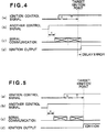
- Fig. 4 shows a case wherein the ignition control signal is output during the serial communication based on the state change of another control signal.
- the transmitting section 20 Upon lapsing of the standby time t from the time of output of another control signal shown in (b) of Fig. 4, the transmitting section 20 latches each signal at the time of lapsing of the standby time t and starts the relevant serial transmission, as shown in (c) of Fig. 4. Where the ignition control signal is output during such transmission as shown in (a) of Fig. 4, the transmitting section 20 latches each control signal and starts the relevant serial transmission after the previous transmission is finished. As a result, the point at which the actual spark is effected by the ignition control signal transmitted to the controlled section 50 comes after the target ignition point (ignition delay). Such a delay error becomes maximum when the ignition control is output immediately after each control signal is latched based on the state change of another control signal. The maximum value of the delay error is equal to the standby time t and may be, for example, 1 ⁇ 2 of the communication time T.
- the communication control device 1 shown in Fig. 1 is arranged to output such control signals the communication time T plus the standby time t (T + t) earlier than desired operation timing and to serial transmit the control signals at the time of lapsing of the standby time t from the time of output of the control signals.
- the transmission of the control signals to the controlled section is timed to be within a range of the standby time t relative to the desired operation point (timing). For example, it may be within a range of ⁇ 1 ⁇ 2 times the communication time T.
- Fig. 5 shows a case wherein the ignition control signal is output during the serial transmission conducted on the basis of the state change in another control signal. This arrangement may be incorporated into the communication control device.
- the transmitting section 20 Upon lapsing of the standby time t from the time of change in the state of another control signal shown in (b) of Fig. 5, the transmitting section 20 latches each control signal at the time of lapsing of the standby time t and commences the serial transmission of the control signal, as shown in (c) of Fig. 5.
- the transmitting section 20 latches and commences the serial transmission of each control signal at the later time. Consequently, the timing in which the ignition control signal is transmitted to the controlled section 50 to initiate the actual ignition operation coincides with the target ignition timing.
- Figs. 6 to 8 Shown in Figs. 6 to 8 are cases wherein the standby time t is T/2 ⁇ t ⁇ T.
- Fig. 6 shows a case wherein the ignition control signal is output in a time period from the time of the state change in another control signal to the time of lapsing of the standby time t.
- the transmitting section 20 latches all the control signals, including the ignition control signal, upon lapsing of the standby time t from the time of detection of the state change of another control signal shown in (b) of Fig. 6 and serial transmits the latched control signals.
- the controlling section 10 Since the controlling section 10 outputs the ignition control signal the communication time T plus the standby time t earlier than the target ignition point, the ignition output is output at a time earlier than the target ignition timing, as shown in (d) of Fig. 6. This produces an advance error wherein the actual ignition spark is made to occur the standby time t earlier than the target ignition point (timing).
- the advance error relative to the ignition point becomes maximum.
- the maximum value of the advance error becomes substantially equal to the communication time T when the value of t is made to be equivalent to the value of T.
- Fig 7 illustrates a case wherein the ignition control signal is output during the serial transmission conducted on the basis of the state change of another control signal.
- the illustrated arrangement may be incorporated into the above-described communication control device.
- the transmitting section 20 Upon lapsing of the standby time t from the time of occurrence of the state change of another control signal shown in (b) of Fig. 7, the transmitting section 20 latches each control signal as of the time of lapsing of the standby time t and commences the serial transmission thereof, as shown in (c) of Fig. 7.
- the transmitting section 20 latches each control signal upon completion of the previous communication and commences the serial transmission thereof.
- the time in which the actual ignition operation is effected in the controlled section 50 by the ignition control signal transmitted thereto occurs the standby time t earlier than the target ignition point, thereby producing an advance error.
- This advance error becomes maximum when the ignition control signal is output immediately before the completion of the serial transmission of another control signal.
- the maximum value of the advance error becomes substantially equal to the communication time T when the value of t is made to be generally equivalent to the value of T.
- Fig. 8 shows a case wherein the ignition control signal to output during the serial communication conducted on the basis of the state change of another control signal.
- the illustrated arrangement may be incorporated into the above-described communication control device.
- the transmitting section 20 Upon lapsing of the standby time t from the time of occurrence of the state change of another control signal shown in (b) of Fig. 8, the transmitting section 20 latches each control signal as of the time of lapsing of the standby time t and commences the serial transmission thereof, as shown in (c) of Fig. 8.
- the transmitting section 20 latches each control signal upon completion of the previous communication and commences the serial transmission thereof. Consequently, the time in which the actual ignition operation is effected in the controlled section 50 by the ignition control signal transmitted thereto occurs
- This delay error becomes maximum when the ignition control signal is output immediately after the start of the serial transmission of another control signal.
- the maximum value of the delay error becomes generally T/2 when the value of t is made to be substantially T/2.
- the delay error can be decreased while the advance error can be increased with the increase of the standby time t.
- This arrangement is effective in a case wherein the occurrence of the delay error is undesirable but the occurrence of the advance error is permitted.
- a suppression time for suppressing transmission in accordance with the state change of another control signal may be provided before the desired operation time.
- the suppression time may have a value larger than the communication time T and smaller than two times the communication time T. This arrangement makes it possible to make the controlled object operate at the desired operation time.
- the controlling section 10 may be formed by using a one-chip microcomputer or a microcomputer system. In this case, control information may be supplied through a data bus to the transmitting section 20 and the state change detecting section 21 without providing any dedicated ports for outputting plural control signals.
- the transmitting section 20 and the state change detecting section 21 may be formed by using a general-purpose serial transmission LSI. Further, the controlling section 10, the transmitting section 20 and the state change detecting section 21 may be integrated by using a one-chip microcomputer including a serial transmission circuit such that the transmission of control signals can be program (software) controlled.
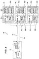
- Fig. 9 schematically illustrates in block diagram the general arrangement of a separate communication control device to which the basic principle of the present invention is applied.
- the communication control device 60 comprises a main control system 70, subsystems 81, 82, 83 and a bidirectional serial transmission line 75 connecting the main control system 70 and the subsystems 81, 82, 83.
- the two-way transmission namely, the transmission of a control signal DM from the main control system 70 to the subsystems 81, 82, 83 and the transmission of verification signals from the subsystems 81, 82, 83 to the main system 70 are effected over the bidirectional serial transmission line 75.
- the main control system 70 comprises a CPU 71 and a communication IC 72.
- the CPU 71 carries out calculations and processing required for the control of the subsystems 81, 82, 83. For example, the CPU 71 generates a control signal for driving an ignition driver 91 of the subsystem 81, converts in the communication IC 72 the control signal into a control signal DM according to the relevant communication protocol, and then transmits the converted control signal DM to the bidirectional serial transmission line 75.
- the CPU 71 is connected with the subsystems 81, 82, 83 through an analog bus 76 so that it can receive analog signals detected by sensors 91D of the subsystems 81, 82, 83, A-D (analog/digital) converts the received sensor signals, and carries out calculations and processing on the resulted digital sensor signals to thereby produce control signals.
- A-D analog/digital
- Each subsystem 81, 82, 83 includes a communication IC with a selector 91B, plural drivers 91C (e.g., an ignition driver, an FI driver and an ABS driver), and plural sensors 91D.
- a selector 91B e.g., an ignition driver, an FI driver and an ABS driver
- plural sensors 91D e.g., an FI driver and an ABS driver
- Sensor signals detected by each sensor 91D are selected in sequence by the respective selectors and supplied to an A/D converter in the CPU 71 of the main control system 70 via the analog bus 76.
- the sequencing of the sensor signals of the subsystems 81, 82, 83 may be executed by transmitting from the CPU 71 of the main control system 70 to the subsystems 81, 82, 83 instruction codes as control signals DM and sequentially switching the selectors 91B.
- Communication ICs 91A of the subsystems 81, 82, 83 receive the control signals DM from the main system 70 and control the drive of the various drivers 91C including the ignition driver, the FI driver and the ABS driver on the basis of the control signals (by, for example, digital/analog conversion thereof).
- the communication ICs 91A also transmit to the main system 70 over the bidirectional serial transmission line 75 confirmation signals DA confirming that the ignition driver, FI driver and ABS driver are actuated, as well as other communication signals.
- the CPU 71 and the communication IC 72 correspond respectively to the controlling section 10 and the transmitting section 20 of Fig. 1.
- a transmission line which allows for bidirectional communication is used as the serial transmission line with the result that collisions between the communications of the main control system 70 and the subsystems 81, 82, 83 may occur.
- priority may be given to the signal transmissions (communications) to and from the main system 70 and subsystems 81, 82, 83.
- first priority may be given to the signal transmissions by the main system 70, second priority to the signal transmissions by the subsystem 81; third priority to the signal transmissions by the subsystem 82; and fourth priority to the signal transmissions by the subsystem 83.
- the communication ICs may be arranged so that they can identify the communication currently occupying the bidirectional serial transmission line 75 and its priority and that when it detects a priority not of its own, it discontinues the signal transmission of its own to the bidirectional serial transmission line 75.
- the main control system 70 and one of the subsystems 81, 82, 83 initiated their communications at the same time, since the main control system 70 is given the first priority, the communication of the main control system 70 is executed to thereby actuate the respective driver of the respective subsystem 81, 82, 83, while the communication of the one subsystem 81, 82, 83 is discontinued.
- the target timing displacement may not occur even where the main control system 70 likes to transmit the control signal DM while the signal DA of the one subsystem 81, 82, 83 is present in the bidirectional serial transmission line 75, because the communication of the one subsystem 81, 82, 83 is completed within the preceding standby time of the main control system 70.
- each subsystem 81, 82, 83 since the transmission time of each subsystem 81, 82, 83 is restricted to be within the standby time upon the commencement of the communication at the main system 60, it becomes possible to actuate the subsystems 81, 82, 83 at the target time point even when a communication request is made by the main control system 70 while one of the subsystems 81, 82, 83 is conducting its communication over the bidirectional serial transmission line 75.
Landscapes
- Engineering & Computer Science (AREA)
- Theoretical Computer Science (AREA)
- Signal Processing (AREA)
- Chemical & Material Sciences (AREA)
- Combustion & Propulsion (AREA)
- Mechanical Engineering (AREA)
- General Engineering & Computer Science (AREA)
- Selective Calling Equipment (AREA)
- Communication Control (AREA)
- Combined Controls Of Internal Combustion Engines (AREA)
- Electrical Control Of Ignition Timing (AREA)
Applications Claiming Priority (6)
| Application Number | Priority Date | Filing Date | Title |
|---|---|---|---|
| JP15200897 | 1997-06-10 | ||
| JP15200897 | 1997-06-10 | ||
| JP152008/97 | 1997-06-10 | ||
| JP16031198 | 1998-06-09 | ||
| JP160311/98 | 1998-06-09 | ||
| JP16031198A JP3827121B2 (ja) | 1997-06-10 | 1998-06-09 | 通信制御装置 |
Publications (3)
| Publication Number | Publication Date |
|---|---|
| EP0884474A2 true EP0884474A2 (de) | 1998-12-16 |
| EP0884474A3 EP0884474A3 (de) | 2000-10-25 |
| EP0884474B1 EP0884474B1 (de) | 2005-02-09 |
Family
ID=26481061
Family Applications (1)
| Application Number | Title | Priority Date | Filing Date |
|---|---|---|---|
| EP98304610A Expired - Lifetime EP0884474B1 (de) | 1997-06-10 | 1998-06-10 | Kommunikationssteuereinrichtung |
Country Status (3)
| Country | Link |
|---|---|
| EP (1) | EP0884474B1 (de) |
| JP (1) | JP3827121B2 (de) |
| DE (1) | DE69828922T2 (de) |
Cited By (1)
| Publication number | Priority date | Publication date | Assignee | Title |
|---|---|---|---|---|
| EP1034982A3 (de) * | 1999-03-10 | 2003-12-17 | Denso Corporation | Automobilsteuereinheit mit unterschiedliche Programmmodule |
Families Citing this family (1)
| Publication number | Priority date | Publication date | Assignee | Title |
|---|---|---|---|---|
| JP5557651B2 (ja) * | 2010-08-19 | 2014-07-23 | 株式会社ケーヒン | エンジン制御システム |
Family Cites Families (7)
| Publication number | Priority date | Publication date | Assignee | Title |
|---|---|---|---|---|
| FR2478913A1 (fr) * | 1980-03-20 | 1981-09-25 | Telediffusion Fse | Concentrateur de systeme de communication pour relier plusieurs terminaux asynchrones de teleinformatique |
| JPS60229567A (ja) * | 1984-04-27 | 1985-11-14 | Usac Electronics Ind Co Ltd | 通信回線における送信モードと受信モードとの選択制御方式 |
| JPS61270947A (ja) * | 1985-05-27 | 1986-12-01 | Nippon Telegr & Teleph Corp <Ntt> | ネツトワ−クの制御方式 |
| JPS6481544A (en) * | 1987-09-24 | 1989-03-27 | Japan Radio Co Ltd | Plural type cdt system using one radio wave |
| KR100191336B1 (ko) * | 1990-01-22 | 1999-06-15 | 렌나르트손켄트 | 분산제어 체계용 배열 |
| JPH05268661A (ja) * | 1992-03-02 | 1993-10-15 | Nec Eng Ltd | 監視制御通信方式 |
| JPH06334668A (ja) * | 1993-05-25 | 1994-12-02 | Furukawa Electric Co Ltd:The | 多重伝送方式 |
-
1998
- 1998-06-09 JP JP16031198A patent/JP3827121B2/ja not_active Expired - Lifetime
- 1998-06-10 EP EP98304610A patent/EP0884474B1/de not_active Expired - Lifetime
- 1998-06-10 DE DE69828922T patent/DE69828922T2/de not_active Expired - Fee Related
Cited By (1)
| Publication number | Priority date | Publication date | Assignee | Title |
|---|---|---|---|---|
| EP1034982A3 (de) * | 1999-03-10 | 2003-12-17 | Denso Corporation | Automobilsteuereinheit mit unterschiedliche Programmmodule |
Also Published As
| Publication number | Publication date |
|---|---|
| JPH1168883A (ja) | 1999-03-09 |
| DE69828922D1 (de) | 2005-03-17 |
| DE69828922T2 (de) | 2006-04-13 |
| EP0884474A3 (de) | 2000-10-25 |
| JP3827121B2 (ja) | 2006-09-27 |
| EP0884474B1 (de) | 2005-02-09 |
Similar Documents
| Publication | Publication Date | Title |
|---|---|---|
| DE112008004194B4 (de) | Elektronisches fahrzeugsteuersystem, elektronischefahrzeugsteuereinheit und fahrzeugsteuerungs-synchronisationsverfahren | |
| AU2012216452B2 (en) | Engine control using an asynchronous data bus | |
| CA3006526A1 (en) | Efficient control assembly and control method | |
| JPH089476A (ja) | 車両通信システム | |
| GB2250107A (en) | Electronic control system for a motor vehicle | |
| US4212080A (en) | Data transmission control system | |
| EP0894975B1 (de) | Elektronische Steuereinrichtung für Fahrzeuge mit einem A/D Wandler zur synchronen und asynchronen A/D Umwandlung | |
| US6218954B1 (en) | Communication control device | |
| JP3637029B2 (ja) | 車載電子制御装置 | |
| EP0884474B1 (de) | Kommunikationssteuereinrichtung | |
| US5737630A (en) | Communication device for synchronized serial communication | |
| JPH05153192A (ja) | 高速遷移信号通信システム | |
| JPH09226482A (ja) | 車両用通信制御装置 | |
| US20040153237A1 (en) | Control device for an internal combustion engine | |
| KR100806460B1 (ko) | 데이터 버스를 통해 적어도 하나의 외부 출력단을제어하기 위한 방법 및 상기 방법을 실행하기 위한 장치 | |
| JP2001304037A (ja) | 車両用電子制御装置 | |
| JPH04287150A (ja) | 同期式シリアルバス方式 | |
| JP5852914B2 (ja) | 電子制御装置 | |
| JP7410085B2 (ja) | 通信システム及び上位制御装置 | |
| JPH05128065A (ja) | データ通信装置 | |
| EP1754875A2 (de) | Steuereinheit | |
| JPH07317587A (ja) | 車両用内燃機関の制御装置 | |
| JP2936671B2 (ja) | 通信装置 | |
| CN118119764A (zh) | 内燃发动机和用于操作内燃发动机的方法 | |
| JP3255957B2 (ja) | 自動車用電子制御装置 |
Legal Events
| Date | Code | Title | Description |
|---|---|---|---|
| PUAI | Public reference made under article 153(3) epc to a published international application that has entered the european phase |
Free format text: ORIGINAL CODE: 0009012 |
|
| AK | Designated contracting states |
Kind code of ref document: A2 Designated state(s): DE FR GB IT |
|
| AX | Request for extension of the european patent |
Free format text: AL;LT;LV;MK;RO;SI |
|
| PUAL | Search report despatched |
Free format text: ORIGINAL CODE: 0009013 |
|
| AK | Designated contracting states |
Kind code of ref document: A3 Designated state(s): AT BE CH CY DE DK ES FI FR GB GR IE IT LI LU MC NL PT SE |
|
| AX | Request for extension of the european patent |
Free format text: AL;LT;LV;MK;RO;SI |
|
| RIC1 | Information provided on ipc code assigned before grant |
Free format text: 7F 02P 5/15 A, 7F 02D 41/26 B, 7H 04L 12/52 B |
|
| 17P | Request for examination filed |
Effective date: 20010122 |
|
| AKX | Designation fees paid |
Free format text: DE FR GB IT |
|
| 17Q | First examination report despatched |
Effective date: 20040113 |
|
| GRAP | Despatch of communication of intention to grant a patent |
Free format text: ORIGINAL CODE: EPIDOSNIGR1 |
|
| GRAS | Grant fee paid |
Free format text: ORIGINAL CODE: EPIDOSNIGR3 |
|
| GRAA | (expected) grant |
Free format text: ORIGINAL CODE: 0009210 |
|
| AK | Designated contracting states |
Kind code of ref document: B1 Designated state(s): DE FR GB IT |
|
| REG | Reference to a national code |
Ref country code: GB Ref legal event code: FG4D |
|
| REF | Corresponds to: |
Ref document number: 69828922 Country of ref document: DE Date of ref document: 20050317 Kind code of ref document: P |
|
| PLBE | No opposition filed within time limit |
Free format text: ORIGINAL CODE: 0009261 |
|
| STAA | Information on the status of an ep patent application or granted ep patent |
Free format text: STATUS: NO OPPOSITION FILED WITHIN TIME LIMIT |
|
| ET | Fr: translation filed | ||
| 26N | No opposition filed |
Effective date: 20051110 |
|
| PGFP | Annual fee paid to national office [announced via postgrant information from national office to epo] |
Ref country code: IT Payment date: 20070618 Year of fee payment: 10 |
|
| PGFP | Annual fee paid to national office [announced via postgrant information from national office to epo] |
Ref country code: FR Payment date: 20070608 Year of fee payment: 10 |
|
| PGFP | Annual fee paid to national office [announced via postgrant information from national office to epo] |
Ref country code: DE Payment date: 20080619 Year of fee payment: 11 |
|
| PGFP | Annual fee paid to national office [announced via postgrant information from national office to epo] |
Ref country code: GB Payment date: 20080611 Year of fee payment: 11 |
|
| REG | Reference to a national code |
Ref country code: FR Ref legal event code: ST Effective date: 20090228 |
|
| PG25 | Lapsed in a contracting state [announced via postgrant information from national office to epo] |
Ref country code: IT Free format text: LAPSE BECAUSE OF NON-PAYMENT OF DUE FEES Effective date: 20080610 Ref country code: FR Free format text: LAPSE BECAUSE OF NON-PAYMENT OF DUE FEES Effective date: 20080630 |
|
| GBPC | Gb: european patent ceased through non-payment of renewal fee |
Effective date: 20090610 |
|
| PG25 | Lapsed in a contracting state [announced via postgrant information from national office to epo] |
Ref country code: GB Free format text: LAPSE BECAUSE OF NON-PAYMENT OF DUE FEES Effective date: 20090610 |
|
| PG25 | Lapsed in a contracting state [announced via postgrant information from national office to epo] |
Ref country code: DE Free format text: LAPSE BECAUSE OF NON-PAYMENT OF DUE FEES Effective date: 20100101 |