EP0884116A2 - Dispositif de réglage utilisant la détection d'objets pour une hotte de laboratoire - Google Patents
Dispositif de réglage utilisant la détection d'objets pour une hotte de laboratoire Download PDFInfo
- Publication number
- EP0884116A2 EP0884116A2 EP98103026A EP98103026A EP0884116A2 EP 0884116 A2 EP0884116 A2 EP 0884116A2 EP 98103026 A EP98103026 A EP 98103026A EP 98103026 A EP98103026 A EP 98103026A EP 0884116 A2 EP0884116 A2 EP 0884116A2
- Authority
- EP
- European Patent Office
- Prior art keywords
- fume hood
- air
- face velocity
- fume
- radiation
- Prior art date
- Legal status (The legal status is an assumption and is not a legal conclusion. Google has not performed a legal analysis and makes no representation as to the accuracy of the status listed.)
- Withdrawn
Links
Images


Classifications
-
- B—PERFORMING OPERATIONS; TRANSPORTING
- B08—CLEANING
- B08B—CLEANING IN GENERAL; PREVENTION OF FOULING IN GENERAL
- B08B15/00—Preventing escape of dirt or fumes from the area where they are produced; Collecting or removing dirt or fumes from that area
- B08B15/02—Preventing escape of dirt or fumes from the area where they are produced; Collecting or removing dirt or fumes from that area using chambers or hoods covering the area
- B08B15/023—Fume cabinets or cupboards, e.g. for laboratories
-
- G—PHYSICS
- G05—CONTROLLING; REGULATING
- G05D—SYSTEMS FOR CONTROLLING OR REGULATING NON-ELECTRIC VARIABLES
- G05D7/00—Control of flow
- G05D7/06—Control of flow characterised by the use of electric means
- G05D7/0617—Control of flow characterised by the use of electric means specially adapted for fluid materials
- G05D7/0623—Control of flow characterised by the use of electric means specially adapted for fluid materials characterised by the set value given to the control element
-
- F—MECHANICAL ENGINEERING; LIGHTING; HEATING; WEAPONS; BLASTING
- F24—HEATING; RANGES; VENTILATING
- F24F—AIR-CONDITIONING; AIR-HUMIDIFICATION; VENTILATION; USE OF AIR CURRENTS FOR SCREENING
- F24F2110/00—Control inputs relating to air properties
- F24F2110/30—Velocity
Definitions
- the present invention relates generally to the control of the ventilation of laboratory fume hoods, and more particularly to an apparatus for determining the presence and location of objects in a laboratory fume hood, and for controlling the flow of air through the fume hood as a function of the determined presence and location of such objects.
- Fume hoods are utilized in various laboratory environments for providing a work place where potentially dangerous chemicals are used, with the hoods comprising an enclosure having moveable doors at the front portion thereof which can be opened in various amounts to permit a person to gain access to the interior of the enclosure to conduct experiments and the like.
- the enclosure is typically connected to an exhaust system for removing any noxious fumes so that the person will not be exposed to them while performing work in the hood.
- the sash doors of such fume hoods are designed to be opened either vertically or horizontally, and the position of the doors is often referred to as the sash position.
- Fume hood controllers which control the flow of air through the enclosure have become more sophisticated in recent years, and are now able to more accurately maintain the desired flow characteristics to efficiently exhaust the fumes from the enclosure as a function of the desired average face velocity of the opening of the fume hood.
- the average face velocity is generally defined as the flow of air into the fume hood per square foot of open face area of the fume hood, with the size of the open face area being dependent upon the position of one or more of the sash doors (often referred to only as a "sash”) and in most types of enclosures, the amount of bypass opening that is provided when the door or doors are closed.
- the fume hoods are exhausted by an exhaust system that includes a blower that is often capable of being driven at variable speeds to increase or decrease the flow of air from the fume hood to compensate for the varying size of the opening or face.
- a blower that is often capable of being driven at variable speeds connected to the exhaust manifold that is in turn connected to the individual ducts of multiple fume hoods, and dampers may be provided in the individual ducts to control the flow from the individual ducts to thereby modulate the flow to maintain the desired average face velocity.
- sensing devices which are used to detect the presence or absence of individuals in the laboratory room and to lower the volume of flow of air that is exhausted through the fume hoods when people are not present in the laboratory room. This has been accomplished by sensing the presence of individuals in the laboratory room using motion detectors of various kinds. Other techniques sense whether the lights of the room are on, and assume that no one is present if the lights are off. The presumed absence of individuals in the room is used to trigger a setback of flow through the hoods, which necessarily reduces the volume of supply air needed and reduces the energy costs to condition the supply air. The amount of the setback varies with the user, but can approach 50 to 60% of the normal flow for a given face velocity.
- a more detailed object is to provide such an improved controller that is adapted to automatically reduce the flow of air through the fume hood if no objects are detected within the interior of the fume hood, which is indicative that no dangerous fumes are present.
- An ancillary object is to provide such a controller that would reduce the flow to minimal flow volumes which may be virtually no flow if no objects are detected within the fume hood.
- Yet another object is to provide such a controller that includes sensing means that are positioned in proximity to the fume hood so that the sensing means is adapted to detect the existence of objects within the fume hood.
- Still another object is to provide such a controller that includes sensing means that is adapted to detect the position of objects within the fume hood, so that flow levels can be adjusted to provide adequate safety while minimizing flow for the purpose of reducing the attendant costs previously discussed.
- a fume hood controller controls the flow of air through the fume hood in a manner whereby the effective size of the total opening to the fume hood, including the portion of the opening that is not covered by one or more sash doors will have a relatively constant average face velocity of air moving into the fume hood. This means that regardless of the area of the uncovered opening, an average volume of air per unit of surface area of the uncovered portion will be moved into the fume hood.
- the present invention is directed to a controller for a fume hood where the flow of air through the fume hood is controlled to maintain safe operating conditions and also to reduce the flow when possible to save costs.
- the controller includes sensing means for sensing whether objects are in the fume hood and the controller is adapted to control the flow of air through the fume hood as a function of the presence or absence of objects in the fume hood as well as the position of the objects, if present.
- the controller is thereby able to reduce the flow of air through the fume hood to a minimum acceptable flow if no objects exist in the fume hood, which is presumed to indicate that there are no noxious fumes present.
- the controller is also adapted to control the flow as a function of the location of objects within the fume hood.
- the controller is also adapted to control the flow as a function of the location of objects within the fume hood.
- the likelihood of fumes spilling out through the opening of the fume hood is increased the closer the source of the fumes is to the opening.
- the likelihood that fumes would escape from the front is reduced. That being the case, the flow through the fume hood can be reduced to some degree without compromising safety, while still realizing the cost savings associated with less flow.
- FIG. 1 a block diagram is shown of several fume hood controllers 20 interconnected with a room controller 22, an exhaust controller 24 and a main control console 26.
- the fume hood controllers 20 are interconnected with the room controller 22 and with the exhaust controller 24 and the main control console 26 in a local area network illustrated by line 28 which may be a multi-conductor cable or the like.
- the room controller, the exhaust controller 24 and the main control console 26 are typically part of the building main HVAC system in which the laboratory rooms containing the fume hoods are located.
- the fume hood controllers 20 are provided with power through line 30, which is at the proper voltage via a transformer 32 or the like.
- the room controller 22 preferably is of the type which is at least capable of providing a variable air volume to the room, and may be a Landis & Staefa, Inc. System 600 SCU controller.
- the room controller 22 is capable of communicating over the LAN lines 28.
- the room controller is a commercially available controller for which extensive documentation exists.
- the User Reference Manual, Part No. 125-1753 for the System 600 SCU controller is specifically incorporated by reference herein.
- the room controller 22 receives signals via lines 81 from each of the fume hood controllers 20 that provides an analog input signal indicating the volume of air that is being exhausted by each of the fume hood controllers 20 and a comparable signal from the exhaust flow sensor that provides an indication of the volume of air that is being exhausted through the main exhaust system apart from the fume hood exhausts.
- a fume hood controller 20 is illustrated with its input and output connector ports being identified, and the fume hood controller 20 is connected to an operator panel 34. It should be understood that each fume hood will have a fume hood controller 20 and that an operator panel will be provided with each fume hood controller.
- the operator panel 34 is provided for each of the fume hoods and it is interconnected with the fume hood controller 20 by a line 36 which preferably comprises a multi-conductor cable having eight conductors.
- the operator panel has a connector 38, such as a 6 wire RJ11 type telephone jack for example, into which a lap top personal computer or the like may be connected for the purpose of inputting information relating to the configuration or operation of the fume hood during initial installation, or to change certain operating parameters if necessary.
- the operator panel 34 is preferably mounted to the fume hood in a convenient location adapted to be easily observed by a person who is working with the fume hood.
- the fume hood controller operator panel 34 preferably includes a liquid crystal display 40, which when selectively activated, provides the visual indication of various aspects of the operation of the fume hood, including three digits 42 which provide the average face velocity.
- the display 40 illustrates other conditions such as low face velocity, high face velocity and emergency condition and an indication of controller failure.
- the operator panel may have an audible alarm 44 and an emergency purge switch 46 which an operator can press to purge the fume hood in the event of an accident.
- the operator panel has two auxiliary switches 48 which can be used for various customer needs, including day/night modes of operation.
- An alarm silence switch 50 is also preferably provided to extinguish an alarm.
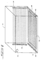
- Fume hoods come in many different styles, sizes and configurations: including those which have a single sash door or a number of sash doors, with the sash doors being moveable vertically, horizontally or in both directions.
- Fume hoods are generally designed so that even when a door sash such as door sash 62 is completely closed, there is still some amount of opening into the fume hood, such as opening 63, through which air can pass.
- This opening 63 is generally referred to as the by-pass area and it can be determined so that its effect can be taken into consideration in controlling the flow of air into the fume hood.
- Some types of fume hoods have a by-pass opening that is located above the door sash while others are below it.
- the first amount of movement of a sash door will increase the opening at the bottom of the door shown in FIG. 3, for example, but as the door is raised, it will merely cut off the by-pass opening so that the size of the total opening of the fume hood is maintained relatively constant for perhaps the first one-fourth amount of movement of the sash door 62 through its course of travel and ignoring any effect of a grille 65 which is provided to overlie the by-pass area.
- fume hoods may include several horizontally moveable sash doors 66 such as shown in FIGS. 4 and 5, with the doors being movable in upper and lower pairs of adjacent tracks 68. When the doors are positioned as shown in FIGS. 4 and 5, the fume hood opening is completely closed and an operator may move the doors in the horizontal direction to gain access to the fume hood.
- Both of the fumes hoods 60 and 64 have an exhaust duct 70 which generally extends to an exhaust system which may be that of the HVAC apparatus previously described.
- the fume hood controller 20 is adapted to operate the fume hoods of various sizes and configurations as has been described, and it is also adapted to be incorporated into a laboratory room where several fume hoods may be located and which may have exhaust ducts which merge into a common exhaust manifold which may be a part of the building HVAC system.
- a fume hood may be a single self-contained installation and may have its own separate exhaust duct. In the event that a single fume hood is installed, it is typical that such an installation would have a variable speed motor driven blower associated with the exhaust duct whereby the speed of the motor and blower can be variably controlled to thereby adjust the flow of air through the fume hood.
- each fume hood is merged into one or more larger exhaust manifolds and a single large blower may be provided in the manifold system.
- control of each fume hood is achieved by means of separate dampers located in the exhaust duct of each fume hood, so that variation in the flow can be controlled by appropriately positioning the damper associated with each fume hood.
- the fume hood controller is adapted to control virtually any of the various kinds and styles of fume hoods that are commercially available, and to this end, it has a number of input and output ports (lines, connectors or connections, all considered to be equivalent herein) that can be connected to various sensors that may be used with the controller. As shown in FIG. 2, it has digital output or DO ports which interface with a digital signal/analog pressure transducer with an exhaust damper as previously described, but it also has an analog voltage output port for controlling a variable speed fan drive if it is to be installed in that manner. There are five sash position sensor ports for use in sensing the position of both horizontally and vertically moveable sashes and there is also an analog input port provided for connection to an exhaust air flow sensor 49.
- a digital input port for the emergency switch is provided and digital output ports for outputting an alarm horn signal as well as an auxiliary signal is provided.
- An analog voltage output port is also provided for providing a volume of flow signal to the room controller 22.
- a wall velocity sensor indicative of face velocity may be utilized and an input port for such a signal is provided, but the use of such sensors is generally considered to be less accurate and is not the preferred embodiment.
- the door sash position sensor comprises an elongated switch mechanism 80 of relatively simple mechanical design which preferably consists of a relatively thin polyester base layer 82 upon which is printed a strip of electrically resistive ink 84 of a known constant resistance per unit length.
- Another polyester base layer 86 is provided and it has a strip of electrically conductive ink 88 printed on it.
- the two base layers 82 and 86 are adhesively bonded to one another by two beads of adhesive 90 located on opposite sides of the strip.
- the base layers are preferably approximately five-thousandths of an inch thick and the beads are approximately two-thousandths of an inch thick, with the beads providing a spaced area between the conductive and resistive layers 88 and 84.
- the switching mechanism 80 is preferably applied to the fume hood by a layer of adhesive 92.
- the polyester material is sufficiently flexible to enable one layer to be moved toward the other so that contact is made in response to a preferably spring biased actuator 94 carried by the appropriate sash door to which the strip is placed adjacent to so that when the sash door is moved, the actuator 94 moves along the switching mechanism 80 and provides contact between the resistive and conductive layers which are then sensed by electrical circuitry to be described which provides a voltage output that is indicative of the position of the actuator 94 along the length of the switching means.
- the actuator 94 is carried by the door and therefore provides an electrical voltage that is indicative of the position of the sash door.
- the actuator 94 is preferably spring biased toward the switching mechanism 80 so that as the door is moved, sufficient pressure is applied to the switching means to bring the two base layers together so that the resistive and conductive layers make electrical contact with one another and if this is done, the voltage level is provided.
- the illustration of the switching mechanism 80 in FIGS. 3 and 5 is intended to be diagrammatic, in that the switching mechanism is preferably actually located within the sash frame itself and accordingly would not be visible as shown.
- the width and thickness dimensions of the switching mechanism are so small that there is little interference with the operation of the sash door.
- the actuator 94 can also be placed in a small hole that may be drilled in the sash door or it may be attached externally at one end thereof so that it can be in position to operate the switch 80. In the vertical moveable sash doors shown in FIGS.
- a switching mechanism 80 is preferably provided in one or the other of the sides of the sash frame, whereas in the fume hoods having horizontally movable doors, it is preferred that the switching mechanism 80 be placed in the top of the tracks 68 so that the weight of the movable doors do not operate the switching mechanism 80 or otherwise damage the same.
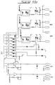
- FIG. 9 the preferred electrical circuitry which generates the position indicating voltage is illustrated, and this circuitry is adapted to provide two separate voltages indicating the position of two sash doors in a single track.
- this circuitry is adapted to provide two separate voltages indicating the position of two sash doors in a single track.
- the switching means is preferably applied to the fume hood with a layer of adhesive 92 and the actuator 94 is adapted to bear upon the switching means at locations along the length thereof.
- FIG. 7 a diagrammatic illustration of a pair of switching means is illustrated such as may occur with respect to the two tracks shown in FIG. 5.
- a switching mechanism 80 is provided with each track and the four arrows illustrated represent the point of contact created by the actuators 94 which result in a signal being applied on each of the ends of each switching means, with the magnitude of the signal representing a voltage that is proportional to the distance between the end and the nearest arrow.
- a single switching mechanism 80 is adapted to provide position indicating signals for two doors located in each track.
- the circuitry that is used to accomplish the voltage generation is shown in FIG.
- the circuitry includes an operational amplifier 100 which has its output connected to the base of a PNP transistor 102, the emitter of which is connected to a source of positive voltage through resistor 104 into the negative input of the operational amplifier, the positive input of which is also connected to a source of positive voltage of preferably approximately five volts.
- the collector of the transistor 102 is connected to one end of the resistive element 84 and has an output line 106 on which the voltage is produced that is indicative of the position of the door.
- the circuit operates to provide a constant current directed into the resistive element 84 and this current results in a voltage on line 106 that is proportional to the resistance value between the collector and ground which changes as the nearest point of contact along the resistance changes.
- the operational amplifier operates to attempt to drive the negative input to equal the voltage level on the positive input and this results in the current applied at the output of the operational amplifier varying in direct proportion to the effective length of the resistance strip 84.
- the lower portion of the circuitry operates the same way as that which has been described and it similarly produces a voltage on an output line 108 that is proportional to the distance between the connected end of the resistance element 84 and the point of contact that is made by the actuator 94 associated with the other sash door in the track.
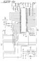
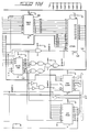
- FIGS. 10a, 10b, 10c, 10d and 10e are placed adjacent one another in the manner shown in FIG. 10, the total electrical schematic diagram of the fume hood controller 20 is illustrated.
- the operation of the circuitry of FIGS. 10a through 10e will not be described in detail.
- the circuitry is driven by a microprocessor and the important algorithms that carry out the control functions of the controller will be hereinafter described.
- the circuitry includes a Motorola MC 68HC11 microprocessor 120 which is clocked at 8 MHz by a crystal 122.
- the microprocessor 120 has a databus 124 that is connected to a tri-state buffer 126 (FIG. 10d) which in turn is connected to an electrically programmable read only memory 128 that is also connected to the databus 124.
- the EPROM 128 has address lines A0 through A7 connected to the tri-state buffer 126 and also has address lines A8 through A14 connected to the microprocessor 120.
- the circuitry includes a 3 to 8-bit multiplexer 130, a data latch 132 (see FIG. 10d), a digital-to-analog converter 134, which is adapted to provide the analog outputs indicative of the volume of air being exhausted by the fume hood, which information is provided to room controller 22 as has been previously described with respect to FIG. 2.
- an RS232 driver 136 is provided for transmitting and receiving information through the hand held terminal.
- the circuitry illustrated in FIG. 9 is also shown in the overall schematic diagrams and is in FIGS. 10a and 10b. The other components are well known and therefore need not be otherwise described.
- the interior of the fume hood has sensing means, which in the preferred embodiment, includes at least a light producing strip 140 located on one side of the interior of the fume hood 60 that have a plurality of light emitting devices 142 each of which is adapted to emit light along a discrete path along the floor of the fume hood 60, which can be detected by a light detecting strip 144 located on the opposite side of the fume hood.
- the detecting strip 144 preferably has a plurality of light detecting devices 146, such as phototransistors that are adapted to detect the presence of an object in between the detector and the light producing strip along a particular path.
- the light producing strip preferably comprises a plurality of light producing devices, such as light emitting diodes that are directed toward specific detectors 146 in the detecting strip 144.
- each of the plurality of light producing devices 142 is associated with one of the light detecting devices 146 to define a light circuit which is adapted to detect the presence or absence of an object along the path of the light.
- the light detecting devices 146 are preferably identified so that if an object is present in the fume hood, and one or more light circuits is broken, the distance the object is located from the front of the fume hood can be determined. Such determination of the location of objects can be used by the controller to control the flow of air through the fume hood.
- a vertically oriented light producing strip 148 and a vertically oriented light detecting strip 150 may be provided, with each being located within approximately 2 to 4 inches from the back wall of the fume hood 60. These strips operate in substantially the same way as the strips 140 and 144, but are positioned to detect objects that may be present on shelves that are commonly present in fume hoods.
- the light circuits should be positioned slightly above the position of each of the shelves and adapted to detect the presence or absence of even short objects that may be present on the shelves.
- the preferred embodiment employs light emitting strips and light detecting strips as described, it should be understood that the use of a strip is not necessary, inasmuch as the light emitting devices and light detecting devices may be individually mounted to the walls of the fume hood.
- the scope of the present invention includes other types of circuits in addition to those described and may include infrared radiation circuits, laser circuits, ultrasonic circuits and other types of circuits.
- the detection of objects on the floor, and even on shelves could be done by load cells or weight measuring devices such as is diagrammatically shown at 152 in FIG. 6, if desired.
- the scope of the present invention may include a video scanning means such as a CCD camera that may be mounted in or outside of the fume hood, but in either case be adapted to view the inside of the fume hood and acquire and analyze images of the inside of the fume hood.
- An image of an empty fume hood can be stored and can be used for comparison purposes to determine the existence of any work objects in the fume hood as well as the position of them if they are present.
- Processing means can then compare the stored image of the empty fume hood with subsequently acquired images and determine if work objects are present in the fume hood.
- control of the air flow through the fume hood can be controlled in a variety of ways, one preferred way is to reduce the flow to a value of approximately 50% of the nominal average face velocity if all objects are within about 2 inches of the back wall of the fume hood, with the nominal face velocity being that which would be used if the objects were within about 6 inches from the front of the fume hood. Control of the face velocity between the 6 inches from the front position to the back can be proportionally scaled. It is also preferred that if a light circuit is interrupted or broken for a location that is closer than 6 inches from the front of the fume hood, that an alarm condition be activated. The alarm can be audio, visual or both.
- the controller reduce the air flow to a minimum condition that may be only 10% to 20% of the nominal average face velocity. While conceivably the flow could be reduced to zero, it is preferred that some number of air changes be made, and the 10% to 20% value will accomplish that.
Applications Claiming Priority (2)
| Application Number | Priority Date | Filing Date | Title |
|---|---|---|---|
| US871112 | 1997-06-09 | ||
| US08/871,112 US5882254A (en) | 1997-06-09 | 1997-06-09 | Laboratory fume hood controller utilizing object detection |
Publications (2)
| Publication Number | Publication Date |
|---|---|
| EP0884116A2 true EP0884116A2 (fr) | 1998-12-16 |
| EP0884116A3 EP0884116A3 (fr) | 2000-04-26 |
Family
ID=25356758
Family Applications (1)
| Application Number | Title | Priority Date | Filing Date |
|---|---|---|---|
| EP98103026A Withdrawn EP0884116A3 (fr) | 1997-06-09 | 1998-02-20 | Dispositif de réglage utilisant la détection d'objets pour une hotte de laboratoire |
Country Status (12)
| Country | Link |
|---|---|
| US (1) | US5882254A (fr) |
| EP (1) | EP0884116A3 (fr) |
| JP (1) | JPH112442A (fr) |
| KR (1) | KR19990006402A (fr) |
| CN (1) | CN1201886A (fr) |
| AU (1) | AU746255B2 (fr) |
| CA (1) | CA2224425A1 (fr) |
| IL (1) | IL123337A (fr) |
| MY (1) | MY133533A (fr) |
| NZ (1) | NZ329425A (fr) |
| SG (1) | SG68653A1 (fr) |
| TW (1) | TW382054B (fr) |
Cited By (2)
| Publication number | Priority date | Publication date | Assignee | Title |
|---|---|---|---|---|
| EP1110627A1 (fr) * | 1999-12-24 | 2001-06-27 | Gitronica S.r.l. | Hotte d'évacuation pour la cuisine |
| FR2811067A1 (fr) | 2000-07-03 | 2002-01-04 | Alain Katz | Systeme et procede de controle de vitesse d'air frontale pour des equipements aerauliques d'extraction, notamment des hottes de laboratoire, et dispositif mis en oeuvre |
Families Citing this family (40)
| Publication number | Priority date | Publication date | Assignee | Title |
|---|---|---|---|---|
| US6154686A (en) * | 1996-07-18 | 2000-11-28 | Innovex Technologies | Distributed architecture |
| US6358137B1 (en) | 2000-04-17 | 2002-03-19 | Siemens Building Technologies, Inc. | Laboratory fume hood control apparatus having rotary sash door position sensor |
| US20110005507A9 (en) * | 2001-01-23 | 2011-01-13 | Rick Bagwell | Real-time control of exhaust flow |
| US6692346B2 (en) * | 2001-08-03 | 2004-02-17 | Fisher Hamilton L.L.C. | Fume hood with alarm system |
| US6960126B2 (en) * | 2002-10-10 | 2005-11-01 | Honeywell International Inc. | Wireless communication for fume hood control |
| US6914532B2 (en) * | 2003-07-30 | 2005-07-05 | Honeywell International Inc. | Method and apparatus for alarm verification in a ventilation system |
| US7001263B2 (en) * | 2003-08-14 | 2006-02-21 | Cornell Research Foundation, Inc. | Air flow monitoring and control system with reduced false alarms |
| PL1778418T5 (pl) | 2004-07-23 | 2014-09-30 | Oy Halton Group Ltd | Ulepszenie sterowania systemów wyciągowych |
| DE102005015754A1 (de) * | 2004-10-20 | 2006-04-27 | E.G.O. Elektro-Gerätebau GmbH | Lüftungsgerät |
| US7198567B2 (en) * | 2004-12-15 | 2007-04-03 | Casey Gary M | Desktop-type ventilation system |
| US7980927B2 (en) * | 2005-04-25 | 2011-07-19 | Flow Sciences, Inc. | Fume hood with floor access opening |
| US20080274683A1 (en) | 2007-05-04 | 2008-11-06 | Current Energy Controls, Lp | Autonomous Ventilation System |
| US20090061752A1 (en) | 2007-08-28 | 2009-03-05 | Current Energy Controls, Lp | Autonomous Ventilation System |
| US20090191803A1 (en) * | 2008-01-24 | 2009-07-30 | Honeywell International Inc. | fume hood system having an automatic decommission mode |
| EP2268976A4 (fr) | 2008-04-18 | 2011-04-20 | Halton Group Ltd Oy | Appareil d'echappement, systeme et procede pour capture et confinement ameliores |
| JP5767974B2 (ja) | 2008-12-03 | 2015-08-26 | オーワイ ハルトン グループ リミテッド | 排気流制御システム及び方法 |
| CN101751029B (zh) * | 2009-11-06 | 2012-05-23 | 国家电网公司交流建设分公司 | 牵引机远程智能协同控制系统及控制方法 |
| CN101825287A (zh) * | 2010-03-10 | 2010-09-08 | 马洪刚 | 一种厨房通风系统及控制方法 |
| US20110279265A1 (en) * | 2010-05-11 | 2011-11-17 | Kewaunee Scientific Corporation | System for displaying information related to an operational parameter of a biological safety cabinet |
| US8908024B2 (en) * | 2011-06-29 | 2014-12-09 | Honeywell International Inc. | System for detecting an item within a specified zone |
| DE102011111949B4 (de) * | 2011-08-29 | 2013-05-29 | Thermo Electron Led Gmbh | Laborabzug und insbesondere Sicherheitswerkbank mit Projektionsvorrichtung |
| DE102012011345A1 (de) * | 2012-06-11 | 2013-12-12 | Köttermann Gmbh & Co. Kg | Laborabzug |
| DE102012011344A1 (de) * | 2012-06-11 | 2013-12-12 | Köttermann Gmbh & Co. Kg | Laborabzug |
| US9694398B2 (en) * | 2012-10-31 | 2017-07-04 | Honeywell International Inc. | Controlling a fume hood airflow using an image of a fume hood opening |
| US9541378B2 (en) * | 2013-03-15 | 2017-01-10 | Siemens Industry, Inc. | Sash position determining system |
| EP2894013B1 (fr) * | 2013-03-29 | 2016-12-14 | Panasonic Healthcare Holdings Co., Ltd. | Isolateur, banc de nettoyage et armoire |
| US10126009B2 (en) | 2014-06-20 | 2018-11-13 | Honeywell International Inc. | HVAC zoning devices, systems, and methods |
| CN104089381B (zh) * | 2014-06-24 | 2016-12-21 | 珠海格力电器股份有限公司 | 检测可燃制冷剂泄漏的装置、方法及空调器 |
| CN104456853B (zh) * | 2014-12-08 | 2017-12-19 | 广东美的制冷设备有限公司 | 空调器的控制方法、空调器的控制系统和空调器 |
| CN105728067B (zh) * | 2016-03-01 | 2017-09-29 | 王俊梅 | 自动调节布风的净气型药品柜 |
| US10376936B2 (en) * | 2016-06-21 | 2019-08-13 | Gurmeet Singh | Method and apparatus of optimizing performance of fume hoods |
| US10384243B2 (en) * | 2017-03-15 | 2019-08-20 | L.B.T. (Nantong) Laboratory Systems Engineering Co., Ltd. | Air replenishing fume hood |
| CN108845033B (zh) * | 2018-06-06 | 2021-02-26 | 北京电子工程总体研究所 | 一种微型探测装置 |
| JP6702376B2 (ja) * | 2018-09-03 | 2020-06-03 | ダイキン工業株式会社 | 送風制御装置 |
| US11801538B2 (en) | 2020-03-18 | 2023-10-31 | Measured Air Performance, LLC | System and methods for controlling laboratory fume hood minimum airflow |
| KR102386482B1 (ko) * | 2020-05-15 | 2022-04-14 | 주식회사 지티사이언 | 사용자에 최적화된 실험실 환경 제공 방법 |
| CN112344404B (zh) * | 2020-10-16 | 2022-04-19 | 宁波方太厨具有限公司 | 一种吸油烟机及其控制方法 |
| DE102020129412A1 (de) * | 2020-11-09 | 2022-05-12 | Lab-Concept GmbH | Abzugsvorrichtung mit Volumenstromregelung |
| EP4357678A1 (fr) * | 2022-10-18 | 2024-04-24 | Franke Technology and Trademark Ltd | Hotte aspirante avec détection d'événements |
| CN117102190A (zh) * | 2023-10-25 | 2023-11-24 | 浙江之科云启科技有限公司 | 一种生物学实验用通风橱 |
Citations (3)
| Publication number | Priority date | Publication date | Assignee | Title |
|---|---|---|---|---|
| US4624690A (en) * | 1985-06-28 | 1986-11-25 | Markel Industries, Inc. | Apparatus for removing particulates |
| WO1993004324A1 (fr) * | 1991-08-23 | 1993-03-04 | Phoenix Controls Corporation | Procede et appareil de commande d'une hotte d'aspiration |
| GB2294395A (en) * | 1994-10-26 | 1996-05-01 | Robert Knight | Ventilated enclosures |
Family Cites Families (6)
| Publication number | Priority date | Publication date | Assignee | Title |
|---|---|---|---|---|
| US4466341A (en) * | 1982-12-17 | 1984-08-21 | Grogan Dennis R | Fume hood energy controller |
| US4744305A (en) * | 1986-04-21 | 1988-05-17 | B.C. Rail | Exhaust removal system |
| US4893551A (en) * | 1988-05-19 | 1990-01-16 | Phoenix Controls Corporation | Fume hood sash sensing apparatus |
| US4982605A (en) * | 1989-05-17 | 1991-01-08 | Alnor Instrument Company | Air flow monitor and temperature compensating circuit therefor |
| US5090303A (en) * | 1990-09-28 | 1992-02-25 | Landis & Gyr Powers, Inc. | Laboratory fume hood control apparatus having improved safety considerations |
| US5406073A (en) * | 1993-01-25 | 1995-04-11 | Phoenix Controls Corporation | System for detecting a movable entity within a selected space |
-
1997
- 1997-06-09 US US08/871,112 patent/US5882254A/en not_active Expired - Fee Related
- 1997-12-10 CA CA002224425A patent/CA2224425A1/fr not_active Abandoned
- 1997-12-11 TW TW086118658A patent/TW382054B/zh not_active IP Right Cessation
- 1997-12-17 NZ NZ329425A patent/NZ329425A/xx unknown
-
1998
- 1998-02-06 CN CN98104379A patent/CN1201886A/zh active Pending
- 1998-02-17 IL IL12333798A patent/IL123337A/en not_active IP Right Cessation
- 1998-02-18 AU AU55365/98A patent/AU746255B2/en not_active Ceased
- 1998-02-20 EP EP98103026A patent/EP0884116A3/fr not_active Withdrawn
- 1998-03-03 SG SG9800478A patent/SG68653A1/en unknown
- 1998-04-15 JP JP10104757A patent/JPH112442A/ja active Pending
- 1998-04-24 KR KR1019980014791A patent/KR19990006402A/ko not_active Application Discontinuation
- 1998-06-08 MY MYPI98002540A patent/MY133533A/en unknown
Patent Citations (3)
| Publication number | Priority date | Publication date | Assignee | Title |
|---|---|---|---|---|
| US4624690A (en) * | 1985-06-28 | 1986-11-25 | Markel Industries, Inc. | Apparatus for removing particulates |
| WO1993004324A1 (fr) * | 1991-08-23 | 1993-03-04 | Phoenix Controls Corporation | Procede et appareil de commande d'une hotte d'aspiration |
| GB2294395A (en) * | 1994-10-26 | 1996-05-01 | Robert Knight | Ventilated enclosures |
Cited By (3)
| Publication number | Priority date | Publication date | Assignee | Title |
|---|---|---|---|---|
| EP1110627A1 (fr) * | 1999-12-24 | 2001-06-27 | Gitronica S.r.l. | Hotte d'évacuation pour la cuisine |
| FR2811067A1 (fr) | 2000-07-03 | 2002-01-04 | Alain Katz | Systeme et procede de controle de vitesse d'air frontale pour des equipements aerauliques d'extraction, notamment des hottes de laboratoire, et dispositif mis en oeuvre |
| EP1301749B1 (fr) * | 2000-07-03 | 2013-07-31 | Alain Katz | Installation avec un systeme de controle de vitesse d'air, notamment dans des hottes de laboratoire |
Also Published As
| Publication number | Publication date |
|---|---|
| MY133533A (en) | 2007-11-30 |
| IL123337A (en) | 2001-08-08 |
| IL123337A0 (en) | 1998-09-24 |
| JPH112442A (ja) | 1999-01-06 |
| AU5536598A (en) | 1998-12-10 |
| EP0884116A3 (fr) | 2000-04-26 |
| TW382054B (en) | 2000-02-11 |
| KR19990006402A (ko) | 1999-01-25 |
| US5882254A (en) | 1999-03-16 |
| NZ329425A (en) | 1998-12-23 |
| SG68653A1 (en) | 2002-04-16 |
| CA2224425A1 (fr) | 1998-12-09 |
| CN1201886A (zh) | 1998-12-16 |
| AU746255B2 (en) | 2002-04-18 |
Similar Documents
| Publication | Publication Date | Title |
|---|---|---|
| US5882254A (en) | Laboratory fume hood controller utilizing object detection | |
| US5090303A (en) | Laboratory fume hood control apparatus having improved safety considerations | |
| US5115728A (en) | System for controlling the differential pressure of a room having laboratory fume hoods | |
| US5733188A (en) | Speed of laboratory fume hood sash opening monitor and indicator | |
| EP0541864B1 (fr) | Méthode et dispositif pour déterminer la dimension de la partie non-recouverte d'une ouverture apte à être recouverte par plusieurs portes mobiles | |
| US5092227A (en) | Apparatus for controlling the ventilation of laboratory fume hoods | |
| AU666609B2 (en) | Method and apparatus for controlling fume hood face velocity using variable by-pass resistance | |
| US6358137B1 (en) | Laboratory fume hood control apparatus having rotary sash door position sensor | |
| US5090304A (en) | Apparatus for determining the position of a moveable structure along a track | |
| US20020155807A1 (en) | Device for controlling an air-moving apparatus upon activation of a smoke detector | |
| AU653557B2 (en) | A method and apparatus for determining the uncovered size of an opening adapted to be covered by multiple moveable doors | |
| AU635696B1 (en) | Apparatus for determining the position of a moveable structure along a track | |
| AU635694B1 (en) | System for controlling the differential pressure of a room having laboratory fume hoods | |
| JP2709871B2 (ja) | 可動構造体の位置を求める装置 | |
| AU635484B1 (en) | Apparatus for controlling the ventilation of laboratory fume hoods | |
| CA2055126C (fr) | Appareil servant a regulariser la ventilation des hottes d'evacuation des gaz de laboratoire | |
| CA2055101C (fr) | Systeme de controle de la pression differentielle d'une piece munie de hottes aspirantes de laboratoire | |
| JP2020094498A (ja) | 送風機 | |
| CA2055147C (fr) | Appareil permettant de determiner la grandeur de l'ouverture laissee par des panneaux mobiles multiples et methode connexe | |
| AU635695B1 (en) | Laboratory fume hood control apparatus having improved safety considerations | |
| CA2055100A1 (fr) | Hotte aspirante de laboratoire a securite superieure | |
| KR20220160515A (ko) | 공기조화기 | |
| KR20190106064A (ko) | 공기조화기 | |
| JPH05165529A (ja) | 煙霧フードの換気を制御する装置 |
Legal Events
| Date | Code | Title | Description |
|---|---|---|---|
| PUAI | Public reference made under article 153(3) epc to a published international application that has entered the european phase |
Free format text: ORIGINAL CODE: 0009012 |
|
| AK | Designated contracting states |
Kind code of ref document: A2 Designated state(s): CH DE FR GB LI |
|
| AX | Request for extension of the european patent |
Free format text: AL;LT;LV;MK;RO;SI |
|
| PUAL | Search report despatched |
Free format text: ORIGINAL CODE: 0009013 |
|
| AK | Designated contracting states |
Kind code of ref document: A3 Designated state(s): AT BE CH DE DK ES FI FR GB GR IE IT LI LU MC NL PT SE |
|
| AX | Request for extension of the european patent |
Free format text: AL;LT;LV;MK;RO;SI |
|
| RAP1 | Party data changed (applicant data changed or rights of an application transferred) |
Owner name: SIEMENS BUILDING TECHNOLOGIES, INC. |
|
| 17P | Request for examination filed |
Effective date: 20000801 |
|
| AKX | Designation fees paid |
Free format text: CH DE FR GB LI |
|
| 17Q | First examination report despatched |
Effective date: 20020405 |
|
| GRAH | Despatch of communication of intention to grant a patent |
Free format text: ORIGINAL CODE: EPIDOS IGRA |
|
| STAA | Information on the status of an ep patent application or granted ep patent |
Free format text: STATUS: THE APPLICATION IS DEEMED TO BE WITHDRAWN |
|
| 18D | Application deemed to be withdrawn |
Effective date: 20030315 |