EP0883996A2 - Haushaltgerät zur Herstellung von Jogurt oder Käse - Google Patents
Haushaltgerät zur Herstellung von Jogurt oder Käse Download PDFInfo
- Publication number
- EP0883996A2 EP0883996A2 EP98304372A EP98304372A EP0883996A2 EP 0883996 A2 EP0883996 A2 EP 0883996A2 EP 98304372 A EP98304372 A EP 98304372A EP 98304372 A EP98304372 A EP 98304372A EP 0883996 A2 EP0883996 A2 EP 0883996A2
- Authority
- EP
- European Patent Office
- Prior art keywords
- container
- machine
- motor
- yogurt
- paddle
- Prior art date
- Legal status (The legal status is an assumption and is not a legal conclusion. Google has not performed a legal analysis and makes no representation as to the accuracy of the status listed.)
- Withdrawn
Links
Images

Classifications
-
- A—HUMAN NECESSITIES
- A47—FURNITURE; DOMESTIC ARTICLES OR APPLIANCES; COFFEE MILLS; SPICE MILLS; SUCTION CLEANERS IN GENERAL
- A47J—KITCHEN EQUIPMENT; COFFEE MILLS; SPICE MILLS; APPARATUS FOR MAKING BEVERAGES
- A47J36/00—Parts, details or accessories of cooking-vessels
- A47J36/16—Inserts
-
- A—HUMAN NECESSITIES
- A23—FOODS OR FOODSTUFFS; TREATMENT THEREOF, NOT COVERED BY OTHER CLASSES
- A23G—COCOA; COCOA PRODUCTS, e.g. CHOCOLATE; SUBSTITUTES FOR COCOA OR COCOA PRODUCTS; CONFECTIONERY; CHEWING GUM; ICE-CREAM; PREPARATION THEREOF
- A23G9/00—Frozen sweets, e.g. ice confectionery, ice-cream; Mixtures therefor
- A23G9/04—Production of frozen sweets, e.g. ice-cream
- A23G9/08—Batch production
- A23G9/12—Batch production using means for stirring the contents in a non-moving container
-
- A—HUMAN NECESSITIES
- A23—FOODS OR FOODSTUFFS; TREATMENT THEREOF, NOT COVERED BY OTHER CLASSES
- A23G—COCOA; COCOA PRODUCTS, e.g. CHOCOLATE; SUBSTITUTES FOR COCOA OR COCOA PRODUCTS; CONFECTIONERY; CHEWING GUM; ICE-CREAM; PREPARATION THEREOF
- A23G9/00—Frozen sweets, e.g. ice confectionery, ice-cream; Mixtures therefor
- A23G9/04—Production of frozen sweets, e.g. ice-cream
- A23G9/22—Details, component parts or accessories of apparatus insofar as not peculiar to a single one of the preceding groups
-
- A—HUMAN NECESSITIES
- A47—FURNITURE; DOMESTIC ARTICLES OR APPLIANCES; COFFEE MILLS; SPICE MILLS; SUCTION CLEANERS IN GENERAL
- A47J—KITCHEN EQUIPMENT; COFFEE MILLS; SPICE MILLS; APPARATUS FOR MAKING BEVERAGES
- A47J43/00—Implements for preparing or holding food, not provided for in other groups of this subclass
- A47J43/04—Machines for domestic use not covered elsewhere, e.g. for grinding, mixing, stirring, kneading, emulsifying, whipping or beating foodstuffs, e.g. power-driven
- A47J43/07—Parts or details, e.g. mixing tools, whipping tools
- A47J43/08—Driving mechanisms
- A47J43/082—Driving mechanisms for machines with tools driven from the upper side
-
- Y—GENERAL TAGGING OF NEW TECHNOLOGICAL DEVELOPMENTS; GENERAL TAGGING OF CROSS-SECTIONAL TECHNOLOGIES SPANNING OVER SEVERAL SECTIONS OF THE IPC; TECHNICAL SUBJECTS COVERED BY FORMER USPC CROSS-REFERENCE ART COLLECTIONS [XRACs] AND DIGESTS
- Y10—TECHNICAL SUBJECTS COVERED BY FORMER USPC
- Y10S—TECHNICAL SUBJECTS COVERED BY FORMER USPC CROSS-REFERENCE ART COLLECTIONS [XRACs] AND DIGESTS
- Y10S366/00—Agitating
- Y10S366/601—Motor control
Definitions
- the present invention relates generally to kitchen appliances, and more particularly to a machine for preparing any one of yogurt, soft frozen yogurt, hard frozen yogurt and cheese, at home.
- yogurt Because of its taste and nutritional value, yogurt has been an increasingly popular food product. Many brand name yogurt products are available to the consumer in supermarkets. Traditionally, and because of the expense of these products, some consumers attempt to make yogurt at home. Warming devices for making yogurt at home are available and are discussed in the prior art.
- U.S. Patent 4,009,368 to Faivre et al. describes an electrically heated yogurt-making machine having an enclosure containing a receptacle into which milk and a yogurt starter is placed. The enclosure contains an electrical heating element and a fusible material (wax) which is adapted to be heated to a melting point by the heating element. Heat from the melted wax is transferred to the milk container. The purpose of the wax is to provide a thermal mass exhibiting a temperature plateau at or near the optimum for incubating the bacteria used to transform the milk to yogurt.
- wax fusible material
- the yogurt making process requires that the yogurt mix incubate relatively undisturbed for a somewhat unpredictable number of hours until the desired consistency and acidity is achieved. More frequent disturbance results in curdling of the milk product and the formation of cheese. If too high a temperature is employed, it accelerates the process to the point where it is difficult to catch the end-point where consistency and flavor are at their optimum.
- Traditional, home-based, room temperature yogurt techniques are slow, sometimes taking as long as 12 hours.
- the room temperature yogurt process does, however, offer the advantage of allowing it to be checked at reasonable intervals so that the incubation process can be terminated at or near its optimal point by initiating cooling.
- the incubation process can be accelerated to only about four hours by providing a warm environment for the yogurt mix, but if the optimal point is not detected accurately, the yogurt becomes more acidic and less palatable. Thus, considerable operator attention and care is required with prior art warming apparatuses.
- the yogurt making appliance of the present invention obviates these problems. Specifically, the yogurt making machine of the present invention requires no operator intervention or monitoring during the reasonably rapid, warmed incubation process. The warming is automatically terminated at the desired point in the process with refrigeration being initiated automatically to terminate further incubation.
- a further object and advantage of the present invention is that the same machine can be used to facilitate the preparation of frozen yogurt as well as both cultured and artificially curdled cheese products.
- the yogurt making appliance constructed in accordance with the present invention is particularly adapted for use in the home to make yogurt, hard and soft frozen yogurt or ice cream and cheese products.
- the appliance includes an insulated container having a flat base and peripheral side walls defining a non-circular cross-section and an open top through which milk or dried milk and water is added to a yogurt starter, usually yogurt from the supermarket or a remnant of a previous batch.
- a yogurt starter usually yogurt from the supermarket or a remnant of a previous batch.
- One or more of the peripheral side walls, the base or a paddle member have embedded therein or otherwise support an electrical heating element that is adapted to apply heat to the contents of the container.
- a cover member is configured to fit atop the peripheral side walls in covering relation to the open top of the container.
- the cover member includes at least one vent hole formed therethrough, along with a centrally located hole that is adapted to receive a paddle support shaft therethrough.
- the paddle support shaft has a paddle secured to its lower end and the shaft for the paddle is sufficiently long so that with the paddle disposed within the container, the shaft will pass upwardly through the central hole in the cover member.
- Also disposed about the paddle support shaft and positioned atop the cover member is a means for selectively covering and opening the vent hole(s) in the cover member.
- the means for selectively occluding and opening the vent hole(s) is releasibly secured to the cover member by magnetic attraction or otherwise, such that a predetermined force must be applied to the vent hole occluding means before it is able to move relative to the cover member.
- At least one drive motor is affixed to the vent hole occluding means for normally rotating either the paddle support shaft and paddle relative to a stationary container or, in an alternative configuration, at least one drive motor is affixed to the base for normally rotating the container relative to a stationary paddle and attached vent hole occluding means, to periodically test the liquid contents in the container.
- Both configurations rotate the occluding means from a vent hole occluding position to an open position upon the thickening of the contents in the non-circular container sufficient to inhibit the relative rotation of the paddle with respect to the container or the container with respect to the paddle with a resistance force that exceeds the predetermined coupling force existing between the occluding means and the cover member.
- the machine of the present invention When preparing yogurt, the machine of the present invention will preferably be placed within the refrigeration compartment of a household refrigerator and with a power cord for energizing the motor and the heating element extending out of the refrigerator past the soft gasket surrounding the door to a wall outlet.
- a timer is included as a part of the appliance for periodically energizing the motor(s) with a predetermined duty cycle whereby at relatively long periodic intervals, e.g., about every 15 minutes, the motor is energized for a relatively short time interval, e.g., about five seconds. This causes movement of the paddle relative to the container resulting in the consistency of the contents of the container being tested at infrequent intervals.
- the paddle and non-circular container will become locked against rotation and this thereby causes the occluding means to which the motors are affixed to rotate about the paddle support shaft from a vent hole occluding position to a vent hole open position.
- the rotation of the occluding means in the manner described also causes an electrical switch to open, shutting off power to the motor and to the heating element. With the power off and the vent hole(s) open, cool air from the refrigerator will quickly absorb the heat energy within the appliance, terminating the fermentation process.
- the container is preferably designed to have a square periphery around its open upper end and around its inner peripheral side walls and the cover member is also square.
- the cover may be placed atop the container in any one of four positions. It has been found convenient to place a plurality of electrical switch actuators atop the wall of the container and surrounding the opening therein and then provide mating electrical switch contacts on the cover member such that when the cover is placed on the container in a first of the four possible positions, it causes the appliance to operate in a mode to produce yogurt. When the cover is rotated 90° and placed atop the container, only switches for causing the appliance to operate in a mode for producing soft frozen yogurt or ice cream will be actuated.
- the cover When the appliance of the present invention is to be used in preparing frozen yogurt or ice cream, the cover is placed on the container's open top in a different orientation such that cooperating switch and switch actuating devices on the container and cover disconnect the heating element from its source of power.
- a previously chilled freezing bowl dimensioned to fit into the opening in the container is removed from the refrigerator's freezer compartment and inserted into the opening of the container.
- the previously prepared mix is then poured into the freezing bowl, as the drive motors are permitted to continuously drive either rotatable drive shaft and paddle or the container such that the frozen yogurt mix forming on the cylindrical inner wall of the freezing bowl is continuously scraped therefrom.
- agglutinated yogurt curd (Ricotta cheese)
- a yogurt culture which is stirred continuously, agglutinates and forms a curd which may settle as a firm mass sticking to the bottom of the irregular shaped container or it may attach to and shrink on the stirring paddle, forming a ball.
- the paddle increasingly becomes mired in the bottom and which is attached to the irregular shaped container, it causes a force resisting movement of the paddle.
- the inertia of the curd ball on the paddle similarly causes a transient force sufficient to overcome the predetermined force between the occluding means and the cover so that the device opens up the vent holes in the cover and turns off the motor and timer.
- a home appliance useful in preparing yogurt, soft or hard frozen yogurt or ice cream, and cheese from a starter and either bottled milk or a mixture of dried milk and water as well as other ingredients for providing a desired taste and consistency.
- the machine is seen to comprise a base container 12 of generally square configuration defined by a bottom 14 and four mutually perpendicular side walls 16, 18, 20 and 22.
- the container 12 will preferably be molded from a suitable plastic and incorporated into the walls 16, 18, 20 and 22 and/or the bottom 14 is a thermostatically controlled heating element 24, here shown as an elongated coil or serpentine arrangement of a nicrome wire that is arranged to warm the interior and, therefore, the contents of the container.
- the thermostat control is identified by numeral 25 in the drawings.
- the four walls 16-22 define an open upper top 26 having downwardly and inwardly sloping edges as at 28 and 30.
- the mutually perpendicular side walls 16-22 and/or the bottom 14 are preferably formed of materials and insulation so that the heat energy derived by passing electrical current through the heating element 24 will be inwardly directed.
- the upper edges of the four side walls include a plurality of post-like protuberances, as at 32, which are spaced or otherwise distributed at predetermined intervals and, as will be further explained, function as electrical switch actuators.
- the freezing bowl 34 Disposed above the base container 12 in the exploded view of Figure 1 is an optional freezing bowl 34 that is used when preparing such products as hard or soft frozen yogurt or ice cream.
- the freezing bowl which is also of a rectangular outer shape, is dimensioned to be insertable into the base container 12.
- the freezing bowl 34 has a substantially cylindrical inner wall 36, preferably formed from aluminum or microwave heatable stainless steel.
- the inner wall may have a non-stick coating, such as Teflon, thereon to facilitate release of frozen product therefrom.
- Disposed between the cylindrical inner wall 36 and the rectangular outer wall and nearly filling it is a chemical mixture exhibiting a low freezing point, a relatively high latent heat of fusion and a low coefficient of expansion.
- the double-walled freezing bowl 34 has an inwardly and downwardly sloping surface 38 leading to the cylindrical chamber 36. Prior to use, the insert 34 is adapted to be placed in the freezing compartment of a household refrigerator and chilled until the chemical material contained between the walls becomes frozen.
- a cover member 40 Sized to fit atop the rim of the base container 12 is a cover member 40, preferably fabricated from a suitable plastic and having a plurality of vent openings 42, 44 and 46 formed through the thickness dimension thereof.
- a further central opening 48 is also provided for receiving the shaft 50 of a motor-driven drive member 52 therethrough.
- the rectangular cover 40 further includes an additional opening 54 through which liquid ingredients may be poured into the freezing bowl 34 when the cover is in place thereon.
- the opening 54 is vertically aligned with the sloped upper edges of the freezing chamber so that when material is poured through the opening 54, it will flow into the container.
- An integrally molded, upwardly projecting annular wall 53 on cover 40 is designed to cooperate with the downwardly depending rim on drive member 52 to act as a baffle against inadvertent spillage when pouring ingredients into opening 54.
- a snap-in removable cap 55 is used to seal the opening 54.
- the switch contacts 56 may comprise conventional diaphragm-type switches, each comprising first and second layers of metallization that are spaced apart from one another by an apertured insulating strip.
- One of the layers of metallization is deposited on a plastic (Mylar) membrane that when deformed through the aperture in the spacer layer, engages the second layer of metallization.
- the switch actuators 32 themselves may be metal covered and function as a first electrical contact designed to cooperate with second contacts formed in recesses on the undersurface of the cover 40.
- an occluder 60 Disposed atop the cover 40 and loosely surrounding the shaft 50 of the drive member 52 is an occluder 60 having an integrally formed sleeve bearing 62 centrally disposed thereon. Washer-type spacers 63 and 65 fit over shaft 50 on opposite ends of the sleeve bearing 62 to prevent frictional engagement between the occluder 60 and cover 40 and drive member 52.
- a pair of electrical drive motors 64 and 66 are mounted on the occluder 60. As best seen in the enlarged view of Figure 2, the motor 64 and the motor 66 are slide mounted on the occluder 60 and have shafts 68 and 70, respectively, frictionally engaging an elastomeric band 72 deployed about an annular projection 74 that extends downwardly from the undersurface of the drive member 52.
- Tension springs 76 and 78 are operatively coupled via the magnetic cores 80 and 82 of the motors 64 and 66 as well as to the sleeve bearing 62 of the occluder 60.
- the springs function to maintain the motor shafts 68 and 70 in firm engagement with the elastomeric friction band 72 surrounding the annular projection 74 to inhibit slippage of the motor shafts on the friction band.
- a C-clip 85 holds the drive member, occluder and cover together as a unit.
- the paddle support shaft 50 is adapted to be coupled to a stub shaft 84 on a paddle member 86 by a C-clip 85.
- the paddle is disposed within the container 12 and adapted to be driven by the drive shaft 50 when the motors 64 and 66 are simultaneously energized.
- the motors may be arranged to rotate the container relative to a paddle that remains stationary.
- the machine of the present invention may also be constructed so that the heating element may be contained in the paddle rather than the walls of container 12 with slip-ring contacts for coupling electrical power thereto.
- the control circuit 61 disposed on the cover 40 is also wired to an electromagnet 88 having first and second coils of differing numbers of turns such that three different magnitudes of magnetic attractive force can be applied for respectively causing a relatively moderate magnetic attraction to a weak permanent magnet 90 on the occluder 60 or, alternatively, two selectively greater attractive forces.
- the permanent magnet 90 can apply a weak attractive force to the core of the inactive electromagnet 88.
- the occluder 60 is arranged to shift between first and second positions. In the first position, the occluder 60 blocks the vent holes 42, 44 and 46 and in its second position uncovers those holes to expose the contents of the machine within the container 12 to the cooling temperature of a refrigerator in which the machine is placed during use.
- a permanent magnet embedded in the occluder member 60 and identified by numeral 92 cooperates with a magnetic reed switch 94 disposed on the cover 40 to maintain the reed switch 94 closed.
- the reed switch 94 is no longer under the influence of the permanent magnet 92 and its contacts open.
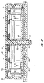
- a power cord 96 has its input prongs adapted to be connected to a source of household current.
- a first insulated conductor in the power cord 96a connects to a first normally open contact 98 of the magnetic reed switch 94 and its second contact 100 is connected by a conductor 102 to a junction point 104 to which one side of the heating element 24 is attached.
- the second conductor of the power cord 96b is connected through terminal point 3 within the control module 61 to the remaining terminal of the heating element 24.
- the junction 104 is also connected to terminal point 2 within the controller module.
- the drive motors 64 and 66 are connected in parallel between the conductor 96b and a terminal point 1 in the controller module.
- a set of normally open timer operated contacts 106 are connected in series between terminal points 1 and 2. While mechanical switch contacts 106 are depicted in the drawings, the controller 61 will typically be a solid state device that will be biased to either a conducting or nonconducting state.
- a yogurt starter and either previously boiled liquid milk or dry, powdered milk plus water is poured into the container 12 and the assembly, including the paddle 86, the drive member 52, the occluder 60 and the rectangular cover 40 are placed, as a unit, atop the container 12 and the drive member 52 is manually rotated in the counterclockwise direction (when viewed as in Figure 1) by placing a finger in the recess 53 formed in the exposed upper surface of drive member 52 to thereby rotate the occluder 60 to its initial position blocking the vent openings 42, 44 and 46 formed through the cover 40.
- the assembly will then be placed within a refrigerator with the power cord 96 extending through the flexible rubber seal of the refrigerator door and then plugged into a wall outlet.
- the permanent magnet 92 embedded in the occluder will cause the contacts of the normally open reed switch 94 to be closed. As such, current will flow through the heating element 24 to begin to warm the milk/starter mix within the container 12. At this time, permanent magnet 90 is attracted to the iron of the unenergized electromagnet 88 with a relatively weak force.
- the timer control 61 will cause the contacts 106 to also close for a relatively short interval.
- the contacts 106 may close about every 15 minutes for a time interval of about five seconds.
- an electrical current is supplied not only to the heater 24, but also to the motors 64 and 66.
- the drive member 52 Upon energization of the motors 64 and 66, and assuming a stationary container 12, the drive member 52 will be rotated in the clockwise direction to also rotate the paddle 86 within the liquid mixture to thereby test the consistency of the constituents. After a few hours, the yogurt mixture will convert from a liquid to a somewhat firm gel. This transition occurs relatively rapidly.
- the motors 64 and 66 will attempt to rotate the drive member 52 and the paddle 86 which are keyed to one another. Because of the rectangular shape of the container 12, the paddle 86 will not only be unable to rotate within the gel but will also be unable to twirl the gelled yogurt and, as a result, the motors affixed to the occluder 60 will overcome the relatively weak magnetic force provided by magnet 90 and will cause the occluder 60 to rotate so as to uncover the vent openings 42, 44 and 46 and simultaneously cause the contacts 98, 100 of the magnetic reed switch 94 to open. Opening of the contacts 98 and 100 disconnects both the heating element 24 and the controller/timer 61 from the power source and thereby shuts off the motors 64 and 66.
- the controller by-pass switch 111 is closed so that the motors 64 and 66 run continuously and the heating element 24 is also energized. Also, the unit need not be set in a refrigerator as increased acidity could be desired and abrupt termination of incubation may not be required.
- the curds agglutinate and become a solid mass. At this point, the cheese mass will inhibit rotation of the paddle 86. This causes the motors to now rotate the occluder, opening the reed switch 94 and disconnecting power from the motors and heating element.
- by-pass switch 111 may be left open and timer/control 61 programmed to cause contacts 106 to open for a relatively short interval.
- the contacts 106 may open, for example, about every 15 minutes for a time interval of about five seconds.
- the paddle either with its attached curd-ball or within a firm or semi-firm mass, reaccelerates, the inertial or resistance force is sufficient to overcome the predetermined weak force between the occluding means and the cover so that the device opens up the vent holes in the cover and turns off the motor and the timer and the heating element.
- the optional insert 34 When it is desired to make soft frozen yogurt, the optional insert 34 is utilized.
- the freezing bowl 34 will have been thoroughly chilled in a freezer or in the freezing compartment of the refrigerator before it is placed into the base container 12.
- Previously prepared frozen yogurt mix is then poured into the cylindrical cavity of the quick freeze insert 34, via access port 54 formed in the cover 40.
- the cover 40 will be installed on the base container 12 in a different orientation than when the machine is being used to create yogurt in the first instance. As will be explained, the repositioning of the cover 40 relative to the base container 12 will result in different modes of operation.
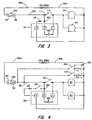
- FIG 4 is a schematic electrical diagram of the apparatus of the present invention when designed for additional or multiple use application.
- the electromagnet 88 is represented by two coils labeled T 1 and T 2 .
- the coils T 1 and T 2 are adapted to be connected between the conductor 102 and the AC supply line 96b when switches 108 and 110 are closed.
- a bypass switch 112 is provided which effectively removes the timer control 60 from the circuit when it is closed.
- the electromagnet 88 has fewer turns on coil T 1 than it does on coil T 2 and, as a result, the electromagnet 88 provides a lesser restraining force to the occluder 60 when the switch 108 is closed than is afforded when switch 110 providing energization to the coil T 2 , is closed.
- a single pole, single throw normally open switch 114 is connected in series with the heating element 24 between terminal 3 of the timer control 60 and junction point 104.
- the open/closed state of the switches 108, 110, 112 and 114 is determined by the orientation of the cover 40 relative to the top of the container 12.
- the switch actuator pins 32 When making regular yogurt, the switch actuator pins 32 will cooperate with the cover such that switch contacts 108, 110 and 112 remain open while contact 114 is closed.
- the cover when making soft, frozen yogurt, the cover will be positioned such that the switch actuators 32 will cooperate with the switches 108, 110, 112 and 114 so that contacts of switch 108 will be closed, 110 will be open, 112 will be closed and 114 will be open.
- motors 64 and 66 will operate continuously. With switch 114 open, no current will flow through the heating element 24.
- the occluder 60 will again rotate due to the stalled condition of the paddle 86.
- the occluder will again reposition so as to open the reed switch contacts 98 and 100 to disconnect the motors 64 and 66 and to remove current from the coil T 1 .
- the machine of the present invention be provided with an audible signaling device which would sound so that the soft frozen yogurt can be removed from the freezing bowl 34 before the yogurt becomes more firm due to the freezing action of the insert.
- the freezing bowl 34 When using the machine of the present invention to produce hard frozen yogurt or ice cream, the freezing bowl 34 is again used, but the cover will now be repositioned on the base container 12 such that the switch actuators 32 cooperate with the switches 56 on the cover 40 to cause switches 110 and 112 to be closed and switches 108 and 114 to be open or switches 108 and 110 may both be closed. Also, the machine of the present invention may be inserted into the refrigerator's freezer compartment. Given the fact that the coil T 2 of the electromagnet 88 has a greater number of turns than the coil T 1 which is active in making soft frozen yogurt, the cover 40 and the occluder 60 will be attracted to one another with an increased force. With switch 114 open, the heating element 24 is not energized.
- the timer circuit 60 is no longer functional and the motors 64 and 66 will run continuously until such time as the magnetic reed switch 94 opens.
- the yogurt will become more and more firm until a point is reached wherein the scraper paddle 86, in attempting to scrape and stir the freezing yogurt, will overcome the force exerted by the coil T 2 of the electromagnet and the motors will then drive the occluder 60 on which they are mounted so as to cause the magnetic reed switch contacts 98 and 100 to open and thereby disconnect the motors and the coil T 2 from the power lines.
- Removal of the frozen product from the bowl 34 may be facilitated by briefly placing the bowl and its frozen contents into a microwave oven and heating it for a short time sufficient to melt the bond of the yogurt to the wall of the bowl.
- a Teflon coating or a plastic liner in the bowl is an alternative solution.
- the freezing bowl is not used and the motors 64 and 66 run continuously or with a duty cycle in which they remain on for a relatively long interval and off for a short interval.
- the heating element will remain energized and the weak magnet 90 will provide the attractive force between the cover 40 and the occluder 60.
- the cover 40 will be positioned on the container such that the switch actuators 32 on the container will cooperate with the switches 56 to cause switch 108 to be open, 110 to be open, 112 to be open, 106 to be open or closed and 114 to be closed.
- the machine may be placed within a refrigerator but this is not necessary.
- the milk and starter will be placed in the container 12 and the occluder positioned so as to occlude the openings 42, 44 and 46 in the cover and to cause the magnetic reed switch 94 to be closed. Because the mixture is being warmed and continuously stirred by the paddle over prolonged periods of time, a point will be reached wherein the mixture begins to flocculate agglutinate and form into a rather firm curdled mass on the bottom of the container. Also, the mass may tend to aggregate or form on the paddle itself.
- any of a variety of electrical slip ring contacts can be used to provide electrical energy to a heating element in a rotating member.
- Another modification would be to sense changes in the current drawn by the motors as the consistency of the product varies from a liquid to a gel or to a solid and use that sensed current change to control the movement of the occluder and to shut off the current to the heating element and to the drive motor(s).
- a safety switch might be incorporated which would shut down all possibility of current flow whenever the cover is removed and, also, a reduced voltage may be utilized for all functions to avoid electrical shock to the user.
- the appliance of the present invention can be modified to permit bread making and other food processing in addition to the other function described herein.
Landscapes
- Engineering & Computer Science (AREA)
- Food Science & Technology (AREA)
- Life Sciences & Earth Sciences (AREA)
- Chemical & Material Sciences (AREA)
- Polymers & Plastics (AREA)
- Manufacturing & Machinery (AREA)
- Mechanical Engineering (AREA)
- Confectionery (AREA)
- Dairy Products (AREA)
- Food-Manufacturing Devices (AREA)
Applications Claiming Priority (2)
| Application Number | Priority Date | Filing Date | Title |
|---|---|---|---|
| US08/872,009 US5829344A (en) | 1997-06-09 | 1997-06-09 | Home yogurt/cheese making machine |
| US872009 | 1997-06-09 |
Publications (2)
| Publication Number | Publication Date |
|---|---|
| EP0883996A2 true EP0883996A2 (de) | 1998-12-16 |
| EP0883996A3 EP0883996A3 (de) | 1999-12-29 |
Family
ID=25358626
Family Applications (1)
| Application Number | Title | Priority Date | Filing Date |
|---|---|---|---|
| EP98304372A Withdrawn EP0883996A3 (de) | 1997-06-09 | 1998-06-03 | Haushaltgerät zur Herstellung von Jogurt oder Käse |
Country Status (2)
| Country | Link |
|---|---|
| US (1) | US5829344A (de) |
| EP (1) | EP0883996A3 (de) |
Cited By (4)
| Publication number | Priority date | Publication date | Assignee | Title |
|---|---|---|---|---|
| EP0997072A1 (de) * | 1998-10-30 | 2000-05-03 | Arnold J. Lande | Haushaltsgerät zur Bereitung von Jogurt oder Käse |
| CN102119758A (zh) * | 2010-12-24 | 2011-07-13 | 施军达 | 上置动力结构的冰激凌机 |
| ITUB20160475A1 (it) * | 2016-01-25 | 2017-07-25 | Edi Fabbro | Macchina e metodo per la produzione di prodotti alimentari |
| CN110120774A (zh) * | 2018-02-05 | 2019-08-13 | 佛山市顺德区美的电热电器制造有限公司 | 烹饪机的调节方法、烹饪机以及存储介质 |
Families Citing this family (23)
| Publication number | Priority date | Publication date | Assignee | Title |
|---|---|---|---|---|
| USD423864S (en) * | 1998-10-02 | 2000-05-02 | Soaring Benefit Ltd. | Yoghort cultivator |
| US5896811A (en) * | 1998-11-10 | 1999-04-27 | Soaring Benefit Ltd. | Yogurt cultivator |
| US20040009610A1 (en) * | 1999-04-29 | 2004-01-15 | The University Of Wyoming Research Corporation D/B/A Western Research Institute | Organic contaminant soil extraction system |
| US7384186B2 (en) * | 2000-05-26 | 2008-06-10 | Timothy J. Williams | Mountable reusable paint container with spigot assembly and stirring mechanism |
| US6758590B1 (en) * | 2001-02-26 | 2004-07-06 | Melvin L. Black, Inc. | Efficient concrete recycling |
| US7172335B1 (en) * | 2002-03-15 | 2007-02-06 | O'connor Carmina F | Automatic mashed potato system |
| US20070140050A1 (en) * | 2005-12-19 | 2007-06-21 | Dave Humphrey Enterprises, Inc. | Concrete slurry tank |
| KR100847770B1 (ko) * | 2006-04-14 | 2008-07-23 | 주식회사 엔유씨전자 | 냉동 요구르트 제조기 및 그 제어방법 |
| US20090139969A1 (en) * | 2007-11-29 | 2009-06-04 | Global Nuclear Fuel - Americas Llc | Laser welding of castings to minimize distortion |
| US20090223385A1 (en) * | 2008-03-06 | 2009-09-10 | Heald Timothy W | Home cheese curd making device |
| DE202008012827U1 (de) | 2008-09-26 | 2008-11-27 | Dr. Herfeld Gmbh & Co. Kg | Mischmaschine |
| US7950844B2 (en) * | 2009-07-15 | 2011-05-31 | Murray Sean T | Cook pot stirrer |
| IT1396769B1 (it) * | 2009-10-23 | 2012-12-14 | Cmt Costr Mecc & Tec | Metodo di trattamento di superfici d'acciaio in macchine casearie |
| USD667706S1 (en) | 2011-03-03 | 2012-09-25 | Hamilton Beach Brands, Inc. | Frozen pop maker |
| US20130186802A1 (en) * | 2012-01-22 | 2013-07-25 | Yul Williams | ThermoTube: A Portable and Human-Powered Food Containment and Temperature Conditioning System |
| EP2921031A1 (de) * | 2012-11-14 | 2015-09-23 | Arçelik Anonim Sirketi | Auf einem induktionskochfeld betriebene lebensmittelzubereitungsvorrichtung |
| USD725428S1 (en) * | 2013-03-01 | 2015-03-31 | Evan Marc Dash | Yogurt maker |
| US9731255B2 (en) | 2013-05-31 | 2017-08-15 | Melvin L. Black | Feedback controlled concrete production |
| US20150071027A1 (en) * | 2013-06-07 | 2015-03-12 | Dimitri Cados | Portable stirring device |
| US9138103B1 (en) * | 2013-06-07 | 2015-09-22 | Dimitri Cados | Portable stirring device |
| USD760533S1 (en) * | 2014-04-25 | 2016-07-05 | Whostyle | Yogurt maker |
| CN109452885B (zh) * | 2017-09-06 | 2022-02-11 | 广东美的生活电器制造有限公司 | 搅拌杯组件和食物料理机 |
| IT201900002391A1 (it) * | 2019-02-19 | 2020-08-19 | De Longhi Appliances S R L Div Commerciale Ariete | Elettrodomestico per la produzione di prodotti caseari |
Family Cites Families (42)
| Publication number | Priority date | Publication date | Assignee | Title |
|---|---|---|---|---|
| US568769A (en) * | 1896-10-06 | Said erben | ||
| US1742878A (en) * | 1929-03-26 | 1930-01-07 | Benjamin Burke Kasloff | Beverage stirrer |
| US2607566A (en) * | 1949-10-21 | 1952-08-19 | Guard It Mfg Company | Pasteurizer |
| SE311924B (de) * | 1963-05-16 | 1969-06-30 | J Maeland | |
| US3685153A (en) * | 1971-01-28 | 1972-08-22 | Edgar B Borkton | Yogurt machine |
| AU472501B2 (en) * | 1971-10-18 | 1976-05-11 | Australian Dairy Corporation | Continuous production of fermented milk |
| US3946657A (en) * | 1972-04-07 | 1976-03-30 | Stiching Bedrijven Van Het Nederlands Instituut Voor Zuivelonderzoek | Process for the continuous preparation of yogurt and other fermented milk products |
| US3921961A (en) * | 1973-04-19 | 1975-11-25 | Raytheon Co | Home freezing appliance |
| FR2244397B1 (de) * | 1973-09-25 | 1978-06-23 | Etud Sa | |
| US4022914A (en) * | 1976-01-28 | 1977-05-10 | Moody Mary B | Preparation of yogurt |
| US4066794A (en) * | 1976-06-23 | 1978-01-03 | Sylvia Schur | Instant yogurt preparation |
| US4066791A (en) * | 1976-08-04 | 1978-01-03 | Diamond Shamrock Corporation | Cheese manufacture with acidified powdered milk |
| ES223410Y (es) * | 1976-09-21 | 1977-04-16 | Aparato productor de leche cuajada de doble ubicacion. | |
| US4163472A (en) * | 1977-06-22 | 1979-08-07 | Michel Cogger | Yogurt maker |
| US4206244A (en) * | 1978-02-06 | 1980-06-03 | Persian Delight, Inc. | Dry mix for preparing a carbonated yogurt |
| IL54049A0 (en) * | 1978-02-15 | 1978-04-30 | Ben Gurion Uni Of The Negev Re | Powdered compositions and methods for the manufacture of acidified milk products |
| US4195561A (en) * | 1978-12-11 | 1980-04-01 | George Castanis | Yogurt maker |
| US4289788A (en) * | 1979-06-25 | 1981-09-15 | M P Food Technology, Inc. | Instant yogurt composition |
| CH646841A5 (en) * | 1980-05-30 | 1984-12-28 | Alfredo Cavalli | Ice-cream machine for domestic use |
| US4624853A (en) * | 1983-02-07 | 1986-11-25 | S. C. Johnson & Son, Inc. | Instant yogurt food product |
| US4497580A (en) * | 1983-12-16 | 1985-02-05 | Doyel John S | Two-motor, battery-operated mixer-pourer |
| IT1173648B (it) * | 1984-05-15 | 1987-06-24 | Alfredo Cavalli | Apparecchiatura ad uso domestico per la produzione di gelato con dispositivo automatico di arresto della pala miscelatrice |
| AT385631B (de) * | 1985-06-26 | 1988-04-25 | Philips Nv | Speiseeismaschine |
| AT386321B (de) * | 1986-01-16 | 1988-08-10 | Philips Nv | Mischwerkzeug fuer eine speiseeismaschine |
| US4719113A (en) * | 1986-05-27 | 1988-01-12 | Kharrazi Nourollah M | Yogurt food product resembling cheese |
| US4802407A (en) * | 1986-06-05 | 1989-02-07 | Philips S.P.A. | Automatic electric household appliance for making cheese and by-products thereof |
| US4885917A (en) * | 1986-10-20 | 1989-12-12 | Donald Spector | Household appliance for making frozen food products |
| US4736600A (en) * | 1987-04-03 | 1988-04-12 | Lester Brown | Modular self-dispensing frozen confectionary maker |
| US4737374A (en) * | 1987-05-07 | 1988-04-12 | Huber Clayton S | Soft-serve frozen yogurt mixes |
| JPS646887U (de) * | 1987-07-02 | 1989-01-13 | ||
| FR2634993B1 (fr) * | 1988-07-06 | 1991-10-04 | Seb Sa | Robot electromenager comprenant un accessoire melangeur chauffant |
| KR910001223B1 (ko) * | 1988-08-29 | 1991-02-26 | 삼성전자 주식회사 | 제빵기의 요구르트 제조장치 및 방법 |
| US5013158A (en) * | 1988-09-29 | 1991-05-07 | Tarlow Kenneth A | Self stirring vessel |
| US5145697A (en) * | 1989-04-26 | 1992-09-08 | Mpy Foods, Inc. | Instant yogurt composition and process |
| US5363746A (en) * | 1990-10-29 | 1994-11-15 | Gordon Ellis D | Automatic food preparation device |
| US5201263A (en) * | 1992-06-12 | 1993-04-13 | Teng Andy C | Cooking utensil with built-in automatic stirring device |
| US5372422A (en) * | 1993-11-29 | 1994-12-13 | Dubroy; Gary P. | Apparatus for automatically stirring food during cooking |
| ATE210926T1 (de) * | 1994-10-12 | 2002-01-15 | Koninkl Philips Electronics Nv | Haushaltgerät zur herstellung von speiseeis |
| US5497695A (en) * | 1994-12-30 | 1996-03-12 | Canela; Heriberto | Food steamer with automatic timed stirring paddle |
| US5516208A (en) * | 1995-03-27 | 1996-05-14 | Givant; Madeline F. | Adjustable pot stirrer |
| US5676463A (en) * | 1996-07-17 | 1997-10-14 | Larsen; Paul R. | Plastic paint mixing system |
| US5711602A (en) * | 1997-03-14 | 1998-01-27 | Rohring; Wesley | Motorized stirring mechanism for a pot |
-
1997
- 1997-06-09 US US08/872,009 patent/US5829344A/en not_active Expired - Fee Related
-
1998
- 1998-06-03 EP EP98304372A patent/EP0883996A3/de not_active Withdrawn
Cited By (6)
| Publication number | Priority date | Publication date | Assignee | Title |
|---|---|---|---|---|
| EP0997072A1 (de) * | 1998-10-30 | 2000-05-03 | Arnold J. Lande | Haushaltsgerät zur Bereitung von Jogurt oder Käse |
| CN102119758A (zh) * | 2010-12-24 | 2011-07-13 | 施军达 | 上置动力结构的冰激凌机 |
| CN102119758B (zh) * | 2010-12-24 | 2013-05-08 | 宁波亿达电器有限公司 | 上置动力结构的冰激凌机 |
| ITUB20160475A1 (it) * | 2016-01-25 | 2017-07-25 | Edi Fabbro | Macchina e metodo per la produzione di prodotti alimentari |
| CN110120774A (zh) * | 2018-02-05 | 2019-08-13 | 佛山市顺德区美的电热电器制造有限公司 | 烹饪机的调节方法、烹饪机以及存储介质 |
| CN110120774B (zh) * | 2018-02-05 | 2021-05-28 | 佛山市顺德区美的电热电器制造有限公司 | 烹饪机的调节方法、烹饪机以及存储介质 |
Also Published As
| Publication number | Publication date |
|---|---|
| EP0883996A3 (de) | 1999-12-29 |
| US5829344A (en) | 1998-11-03 |
Similar Documents
| Publication | Publication Date | Title |
|---|---|---|
| US5829344A (en) | Home yogurt/cheese making machine | |
| US6280781B1 (en) | Home yogurt/cheese making machine | |
| US6213007B1 (en) | Home yogurt/cheese making machine | |
| CN105636681B (zh) | 改进的冰激凌制作机 | |
| AU2012229879B2 (en) | Ice cream maker | |
| CA1302343C (en) | Automatic electric household appliance for making cheese and by-products thereof | |
| CA2587258C (en) | Appliance and method for preparing a froth from a food liquid | |
| US6041614A (en) | Ice-cream maker | |
| RU2722120C2 (ru) | Кухонный прибор с возможностью измерения характеристик пищи и напитков | |
| RU2687684C2 (ru) | Устройство для приготовления напитка, предназначенное для приготовления охлажденных и вспененных напитков | |
| US4716822A (en) | Ice-cream maker | |
| US20080257173A1 (en) | Dessert and ice cream making apparatus | |
| JP4509616B2 (ja) | アイスクリーム製造機及びその制御方法 | |
| JPS60160855A (ja) | 豆腐製造装置 | |
| JPH054889U (ja) | 発酵乳調製品の製造装置 | |
| JPH0714379B2 (ja) | 調理器 | |
| HK1111325B (en) | Appliance for preparing froth from a milk-based liquid |
Legal Events
| Date | Code | Title | Description |
|---|---|---|---|
| PUAI | Public reference made under article 153(3) epc to a published international application that has entered the european phase |
Free format text: ORIGINAL CODE: 0009012 |
|
| AK | Designated contracting states |
Kind code of ref document: A2 Designated state(s): BE CH DE DK FI FR LI NL SE |
|
| AX | Request for extension of the european patent |
Free format text: AL;LT;LV;MK;RO;SI |
|
| PUAL | Search report despatched |
Free format text: ORIGINAL CODE: 0009013 |
|
| AK | Designated contracting states |
Kind code of ref document: A3 Designated state(s): AT BE CH CY DE DK ES FI FR GB GR IE IT LI LU MC NL PT SE |
|
| AX | Request for extension of the european patent |
Free format text: AL;LT;LV;MK;RO;SI |
|
| 17P | Request for examination filed |
Effective date: 20000623 |
|
| AKX | Designation fees paid |
Free format text: BE CH DE DK FI FR LI NL SE |
|
| 17Q | First examination report despatched |
Effective date: 20010130 |
|
| GRAH | Despatch of communication of intention to grant a patent |
Free format text: ORIGINAL CODE: EPIDOS IGRA |
|
| STAA | Information on the status of an ep patent application or granted ep patent |
Free format text: STATUS: THE APPLICATION IS DEEMED TO BE WITHDRAWN |
|
| 18D | Application deemed to be withdrawn |
Effective date: 20031104 |