EP0882483B1 - Filtre pour liquides et gaz - Google Patents
Filtre pour liquides et gaz Download PDFInfo
- Publication number
- EP0882483B1 EP0882483B1 EP98110267A EP98110267A EP0882483B1 EP 0882483 B1 EP0882483 B1 EP 0882483B1 EP 98110267 A EP98110267 A EP 98110267A EP 98110267 A EP98110267 A EP 98110267A EP 0882483 B1 EP0882483 B1 EP 0882483B1
- Authority
- EP
- European Patent Office
- Prior art keywords
- filter
- ring
- outflow
- supporting element
- end disk
- Prior art date
- Legal status (The legal status is an assumption and is not a legal conclusion. Google has not performed a legal analysis and makes no representation as to the accuracy of the status listed.)
- Expired - Lifetime
Links
- 239000007789 gas Substances 0.000 title claims description 4
- 239000007788 liquid Substances 0.000 title claims description 4
- 239000000463 material Substances 0.000 claims description 16
- 238000007789 sealing Methods 0.000 claims description 10
- 239000002184 metal Substances 0.000 claims description 2
- 239000013013 elastic material Substances 0.000 claims 2
- 230000004323 axial length Effects 0.000 description 4
- 238000000034 method Methods 0.000 description 2
- 230000005540 biological transmission Effects 0.000 description 1
- 238000002485 combustion reaction Methods 0.000 description 1
- 150000001875 compounds Chemical class 0.000 description 1
- 238000001914 filtration Methods 0.000 description 1
- 238000004519 manufacturing process Methods 0.000 description 1
- 230000002093 peripheral effect Effects 0.000 description 1
- 238000004382 potting Methods 0.000 description 1
Images


Classifications
-
- B—PERFORMING OPERATIONS; TRANSPORTING
- B01—PHYSICAL OR CHEMICAL PROCESSES OR APPARATUS IN GENERAL
- B01D—SEPARATION
- B01D46/00—Filters or filtering processes specially modified for separating dispersed particles from gases or vapours
- B01D46/24—Particle separators, e.g. dust precipitators, using rigid hollow filter bodies
- B01D46/2403—Particle separators, e.g. dust precipitators, using rigid hollow filter bodies characterised by the physical shape or structure of the filtering element
- B01D46/2411—Filter cartridges
- B01D46/2414—End caps including additional functions or special forms
-
- B—PERFORMING OPERATIONS; TRANSPORTING
- B01—PHYSICAL OR CHEMICAL PROCESSES OR APPARATUS IN GENERAL
- B01D—SEPARATION
- B01D29/00—Filters with filtering elements stationary during filtration, e.g. pressure or suction filters, not covered by groups B01D24/00 - B01D27/00; Filtering elements therefor
- B01D29/11—Filters with filtering elements stationary during filtration, e.g. pressure or suction filters, not covered by groups B01D24/00 - B01D27/00; Filtering elements therefor with bag, cage, hose, tube, sleeve or like filtering elements
- B01D29/13—Supported filter elements
- B01D29/15—Supported filter elements arranged for inward flow filtration
-
- B—PERFORMING OPERATIONS; TRANSPORTING
- B01—PHYSICAL OR CHEMICAL PROCESSES OR APPARATUS IN GENERAL
- B01D—SEPARATION
- B01D29/00—Filters with filtering elements stationary during filtration, e.g. pressure or suction filters, not covered by groups B01D24/00 - B01D27/00; Filtering elements therefor
- B01D29/88—Filters with filtering elements stationary during filtration, e.g. pressure or suction filters, not covered by groups B01D24/00 - B01D27/00; Filtering elements therefor having feed or discharge devices
- B01D29/90—Filters with filtering elements stationary during filtration, e.g. pressure or suction filters, not covered by groups B01D24/00 - B01D27/00; Filtering elements therefor having feed or discharge devices for feeding
- B01D29/902—Filters with filtering elements stationary during filtration, e.g. pressure or suction filters, not covered by groups B01D24/00 - B01D27/00; Filtering elements therefor having feed or discharge devices for feeding containing fixed liquid displacement elements or cores
-
- B—PERFORMING OPERATIONS; TRANSPORTING
- B01—PHYSICAL OR CHEMICAL PROCESSES OR APPARATUS IN GENERAL
- B01D—SEPARATION
- B01D29/00—Filters with filtering elements stationary during filtration, e.g. pressure or suction filters, not covered by groups B01D24/00 - B01D27/00; Filtering elements therefor
- B01D29/88—Filters with filtering elements stationary during filtration, e.g. pressure or suction filters, not covered by groups B01D24/00 - B01D27/00; Filtering elements therefor having feed or discharge devices
- B01D29/90—Filters with filtering elements stationary during filtration, e.g. pressure or suction filters, not covered by groups B01D24/00 - B01D27/00; Filtering elements therefor having feed or discharge devices for feeding
- B01D29/908—Filters with filtering elements stationary during filtration, e.g. pressure or suction filters, not covered by groups B01D24/00 - B01D27/00; Filtering elements therefor having feed or discharge devices for feeding provoking a tangential stream
-
- B—PERFORMING OPERATIONS; TRANSPORTING
- B01—PHYSICAL OR CHEMICAL PROCESSES OR APPARATUS IN GENERAL
- B01D—SEPARATION
- B01D46/00—Filters or filtering processes specially modified for separating dispersed particles from gases or vapours
- B01D46/0039—Filters or filtering processes specially modified for separating dispersed particles from gases or vapours with flow guiding by feed or discharge devices
- B01D46/0041—Filters or filtering processes specially modified for separating dispersed particles from gases or vapours with flow guiding by feed or discharge devices for feeding
- B01D46/0043—Filters or filtering processes specially modified for separating dispersed particles from gases or vapours with flow guiding by feed or discharge devices for feeding containing fixed gas displacement elements or cores
Definitions
- the invention relates to a filter for gases or liquids according to the preambles of independent claims 1 and 8th.
- the end plate is formed as an end cap, which is on the associated End wall is supported in the cover of the filter housing.
- the filter element with the support element on the outlet wall of the filter housing only when the filter housing is fully assembled comes into contact sealingly in the axial direction.
- the invention is concerned with a generic Filters with the problem of a pollution-related Filter element change on the one hand as little material as possible need to replace and on the other hand no expensive, low dimensional tolerances for the seals to be sealed against each other Having to comply with components and still a high one To be able to guarantee functional safety.
- the tension of the end plate against the opposite Front wall with a force path exclusively via the support element and not over the filter material between the front Wrestling of the filter element enables bridging of differences in the axial length of the filter element with the support element while maintaining the seal through the rings.
- the filter element with support element can be cylindrical or conical.
- the support element can preferably be a perforated plate cylinder outflow-side edge which points radially inwards, be formed, the edge of the dimensional stability of the support element improved and with axial sealing of the filter element between the end plate and the outlet opening Front wall of the filter housing also as an internal system Edge area of the outflow-side ring can serve.
- end plate Filter element opposite the end plate One possibility for sealing the end plate Filter element opposite the end plate is that the end plate-side ring faces away from the filter material Has an annular process that is in an annular Collar of the end plate is sealed.
- end plate-side ring is one of the filter material facing away from the ring process, which means an annular clamping element against an annular, cylindrical end edge of the end plate is tightly clamped.
- the independent claim 8 takes place with the execution according to claim 1 matching power transmission the axial clamping force only via the support element the seal of the filter element over a tight radial Contact the front rings of the filter element on the Supporting member.
- Filters according to the invention are in particular as air filters usable for internal combustion engines of commercial vehicles, because in such an application the filter element is special needs to be replaced frequently.
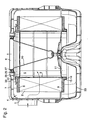
- a filter element 2 is arranged with a support element 3 lying on the inside, which separates an outer inflow space 4 from an inner outflow space 5, to which an outflow opening 6 in an end wall 7 of the filter housing 1 connects.
- the filter element 2 consists of filter material, the two axial ends of which are accommodated in a ring 8, 9 made of potting compound.
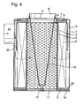
- the support element 3 is designed as a perforated plate cylinder and has at its end facing the outflow opening 6 an edge 13 which points radially inwards.
- the ring 9 facing the end plate 11 has an annular extension 14 facing away from the filter material, which ring is received in a sealing manner in an annular collar 15 of the end plate 11.
- the filter housing 1 together with end walls 7 and 23 are shown as molded parts made of plastic.
- Arranged in the end wall 7 is an annular border 27 of the outflow opening 6, which is made of metal and to which the carrier 10 is fastened.
- This border 27 lies with the interposition of a sealing ring 28 on the corresponding opening in the end wall 7 and is fastened to the end wall 7 by holding members 29.
- the latter also serve to fasten a resilient, annular plate 30 which resiliently rests on the ring 8 and also serves to seal between the inflow space 4 and outflow space 5.
- the ring 9 facing the end plate 11 has an annular extension 16 facing away from the filter material, which is clamped by means of an annular clamping element 17 against an annular, cylindrical end edge 18 of the end plate 11.
- the end plate 11 and the ring 9 facing it have outer diameters which are only slightly smaller than the inner diameter of the filter housing 1.
- This ring 9 projects beyond the outer diameter of the filter material, the protrusion 19 of this ring 9 bears sealingly on an annular collar 20 on the inside of the filter housing 1.
- the support element 3 has at its two axial ends ring-shaped, closed end sections 21, against which the rings 8, 9 lie radially sealingly on the outside.
- An annular seal 26 is arranged between the radially inwardly facing edge 13 at the end of the support body 3 facing the outflow opening 6 and the end wall 7 on the outflow opening side of the filter housing 1. 1, 2, 3 and 5, the screw connection 12 at the end of the carrier 10 is extended by an additional screw connection 22, by means of which the end wall 23 of the filter housing 1 on the end plate side is fastened.
Landscapes
- Chemical & Material Sciences (AREA)
- Chemical Kinetics & Catalysis (AREA)
- Physics & Mathematics (AREA)
- Geometry (AREA)
- Filtering Of Dispersed Particles In Gases (AREA)
- Lubrication Details And Ventilation Of Internal Combustion Engines (AREA)
- Sampling And Sample Adjustment (AREA)
Claims (13)
- Filtre pour gaz ou liquides, dans lequel, dans un logement de filtre (1) approximativement cylindrique, un élément de filtrage (2) en forme d'anneau, remplaçable, à travers lequel le fluide s'écoule de l'extérieur vers l'intérieur sépare un espace d'amenée (4) extérieur d'un espace d'évacuation (5) intérieur, dans lequel l'élément de filtrage est étayé sur son côté intérieur par un élément de support (3) amovible de ce dernier, présentant des ouvertures traversantes et adapté à la forme de l'élément de filtrage, dans lequel l'élément de support est étayé sur une paroi frontale du logement de filtre, laquelle présente une ouverture d'évacuation (6) contiguë à l'espace d'évacuation (5) intérieur, dans lequel, à l'extrémité de l'élément de support qui se détourne de l'ouverture d'évacuation, une rondelle d'extrémité (11) qui obture l'espace d'évacuation est prévue, dans lequel en outre les deux extrémités axiales du matériau de filtrage de l'élément de filtrage s'engagent chacune dans un anneau (8 ;9) constitué de matériau élastique et dans lequel enfin un de ces anneaux (8) sert de joint d'étanchéité relativement à la paroi frontale (7) du côté de l'évacuation du flux et l'autre de ces anneaux (9) sert de joint d'étanchéité relativement à l'élément de support (3) et à la rondelle d'extrémité (11),
caractérisé par les caractéristiques,la rondelle d'extrémité (11) est reliée à l'extrémité de l'élément de support (3) tournée vers cette dernière et pressée par l'intermédiaire dudit élément de support (3) contre la paroi frontale (7) opposée du logement de filtre (1),une partie d'un des anneaux (8) faisant saillie sur le matériau de filtrage dans une direction radiale interne est pressée axialement entre l'élément de support (3) et la paroi frontale (7). - Filtre selon la revendication 1, caractérisé en ce qu'à travers l'espace d'évacuation (5), un support (10) fixé à la paroi frontale (7) du côté de l'ouverture d'évacuation s'étend, sur lequel l'extrémité tournée vers la rondelle d'extrémité (11) est fixée à cette dernière au moyen d'une connexion à vis (12).
- Filtre selon la revendication 1 ou 2, caractérisé en ce que l'élément de support (3) est configuré comme un cylindre perforé avec un bord (13) du côté de l'ouverture d'évacuation, qui se dirige radialement vers l'intérieur.
- Filtre selon la revendication 1,2 ou 3, caractérisé en ce que l'anneau (9) du côté de la rondelle d'extrémité présente un prolongement (14) qui se détourne du matériau de filtrage, lequel s'engage hermétiquement dans un collier (15) en forme d'anneau de la rondelle d'extrémité (11).
- Filtre selon la revendication 1,2 ou 3, caractérisé en ce que l'anneau (9) du côté de la rondelle d'extrémité présente un prolongement (16) qui se détourne du matériau de filtrage, lequel est pressé hermétiquement au moyen d'un élément de serrage (17) en forme d'anneau contre un bord d'extrémité (18) cylindrique, en forme d'anneau de la rondelle d'extrémité (11).
- Filtre selon la revendication 1,2 ou 3, caractérisé en ce que le diamètre externe de la rondelle d'extrémité (11) et le diamètre externe de l'anneau (9) du côté de la rondelle d'extrémité sont moins petits que le diamètre interne du logement de filtre (1) et en ce que cet anneau (9) saille au dessus du diamètre externe du matériau de filtrage, moyennant quoi la protubérance (19) de cet anneau (9) repose hermétiquement sur un collier (20) en forme d'anneau du côté intérieur du logement de filtre (1).
- Filtre selon les revendications 2 et 4 ou 5, caractérisé en ce que la connexion à vis (12) est prolongée par une connexion à vis supplémentaire (22), au moyen de laquelle la paroi frontale (23) du côté de la rondelle d'extrémité du logement de filtre (1) est fixée.
- Filtre pour gaz ou liquides, dans lequel, dans un logement de filtre approximativement cylindrique, un élément de filtrage en forme d'anneau, remplaçable, à travers lequel le fluide s'écoule de l'extérieur vers l'intérieur sépare un espace d'amenée extérieur d'un espace d'évacuation intérieur, dans lequel l'élément de filtrage est étayé sur son côté intérieur par un élément de support amovible de ce dernier, présentant des ouvertures traversantes et adapté à la forme de l'élément de filtrage, dans lequel, à l'extrémité de l'élément de support qui se détourne de l'ouverture d'évacuation, une rondelle d'extrémité qui obture l'espace d'évacuation est prévue, dans lequel en outre les deux extrémités axiales du matériau de filtrage de l'élément de filtrage s'engagent chacune dans un anneau constitué de matériau élastique et dans lequel enfin l'élément de support présente à ses deux extrémités des portions d'extrémité en forme d'anneau, fermées, sur l'extérieur desquelles les anneaux reposent radialement et hermétiquement,
caractérisé par les caractéristiques,l'élément de support (3) est étayé hermétiquement par une paroi frontale du logement de filtre (1), laquelle présente une ouverture d'évacuation contiguë à l'espace d'évacuation interne,la rondelle d'extrémité (11) est reliée à l'extrémité de l'élément de support (3) tournée vers cette dernière et pressée contre la paroi frontale (7) opposée du logement d filtre (1). - Filtre selon la revendication 8, caractérisé en ce que, à travers l'espace d'évacuation (5), un support (10) fixé à la paroi frontale (7) du côté de l'ouverture d'évacuation s'étend, sur lequel l'extrémité tournée vers la rondelle d'extrémité (11) est fixée à cette dernière au moyen d'une connexion à vis (12).
- Filtre selon la revendication 9, caractérisé en ce que la connexion à vis (12) est prolongée par une connexion à vis supplémentaire (22), au moyen de laquelle la paroi frontale (23) du côté de la rondelle d'extrémité du logement de filtre (1) est fixée.
- Filtre selon la revendication 8,9 ou 10, caractérisé en ce que l'élément de support (3) est configuré comme un cylindre perforé avec un bord (13) du côté de l'ouverture d'évacuation, qui se dirige radialement vers l'intérieur.
- Filtre selon une des revendications 2 à 7 ou 9 à 11, caractérisé en ce qu'au moins ladite partie du logement de filtre, sur laquelle repose l'ouverture d'évacuation (6), est constituée de plastique et le support (10) est constitué de métal, moyennant quoi le support (10) est fixé radialement et hermétiquement à la zone du bord de l'ouverture d'évacuation (6).
- Filtre selon la revendication 12, caractérisé en ce que le support (10) est relié à une butée (30) axiale de l'anneau (8) tourné vers l'ouverture d'écoulement (7)de l'élément de filtrage (2).
Applications Claiming Priority (2)
| Application Number | Priority Date | Filing Date | Title |
|---|---|---|---|
| DE19723580 | 1997-06-05 | ||
| DE19723580A DE19723580A1 (de) | 1997-06-05 | 1997-06-05 | Filter für Gase und Flüssigkeiten |
Publications (3)
| Publication Number | Publication Date |
|---|---|
| EP0882483A2 EP0882483A2 (fr) | 1998-12-09 |
| EP0882483A3 EP0882483A3 (fr) | 1998-12-23 |
| EP0882483B1 true EP0882483B1 (fr) | 2004-10-13 |
Family
ID=7831481
Family Applications (1)
| Application Number | Title | Priority Date | Filing Date |
|---|---|---|---|
| EP98110267A Expired - Lifetime EP0882483B1 (fr) | 1997-06-05 | 1998-06-05 | Filtre pour liquides et gaz |
Country Status (2)
| Country | Link |
|---|---|
| EP (1) | EP0882483B1 (fr) |
| DE (2) | DE19723580A1 (fr) |
Families Citing this family (4)
| Publication number | Priority date | Publication date | Assignee | Title |
|---|---|---|---|---|
| US6235073B1 (en) | 1999-11-10 | 2001-05-22 | Nelson Industries, Inc. | Fastener retention system |
| US20040103626A1 (en) * | 2002-08-23 | 2004-06-03 | Warth Scott B. | Filter element, filter assembly, gas turbine system, and methods |
| DE102010034787B4 (de) | 2009-08-31 | 2016-06-23 | Mann + Hummel Gmbh | Filtereinrichtung mit einem ringförmigen Filterelement in einem Filtergehäuse |
| DE102011012633B4 (de) | 2011-02-28 | 2018-04-05 | Mann + Hummel Gmbh | Filtereinrichtung mit einem ringförmigen Filterelement |
Family Cites Families (22)
| Publication number | Priority date | Publication date | Assignee | Title |
|---|---|---|---|---|
| DE1726591U (de) * | 1955-04-23 | 1956-07-19 | Mann & Hummel Filter | Filter, insbesondere luftfilter. |
| DE1202759B (de) * | 1961-02-08 | 1965-10-14 | Dollinger Corp | Filtereinsatz |
| DE1204679B (de) * | 1964-03-28 | 1965-11-11 | Basf Ag | Verfahren zum Abscheiden von Harnstoff aus den von Melamin befreiten Abgasen der in Gasphase durchgefuehrten Melaminsynthese aus Harnstoff |
| DE1902533A1 (de) * | 1969-01-18 | 1970-09-10 | Bauknecht Gmbh G | Entnahmevorrichtung fuer Materialkaesten |
| US3524550A (en) * | 1969-05-23 | 1970-08-18 | Caterpillar Tractor Co | Filter assembly |
| DE1955789B2 (de) * | 1969-11-06 | 1976-08-12 | Purolator Filter GmbH, 7110 Öhringen | Filter aus zickzackfoermig gefaltetem, streifenfoermigen filterpapier |
| DE7400250U (de) * | 1974-01-05 | 1975-01-30 | Mann & Hummel Gmbh | Luftfilter fuer brennkraftmaschinen kompressoren und sonstige luftansaugende maschinen |
| FR2268551B1 (fr) * | 1974-04-24 | 1980-12-05 | Cfea | |
| US4482368A (en) * | 1983-02-28 | 1984-11-13 | Nelson Industries, Inc. | Air cleaning assembly including a fastening assembly having a novel wing nut construction |
| DE8805049U1 (fr) * | 1988-04-16 | 1988-06-01 | Ing. Walter Hengst Gmbh & Co Kg, 4400 Muenster, De | |
| DE3934433A1 (de) * | 1989-10-14 | 1991-04-25 | Mann & Hummel Filter | Luftfilter mit radial abdichtendem filtereinsatz |
| DE4018655C2 (de) * | 1990-06-11 | 2000-07-27 | Hengst Walter Gmbh & Co Kg | Luftfilter |
| DE4024898A1 (de) * | 1990-08-06 | 1992-02-13 | Mann & Hummel Filter | Ansaugluftfilter fuer die verbrennungskraftmaschine eines fahrzeugs |
| DE4102615A1 (de) * | 1991-01-30 | 1992-08-06 | Bayern Chemie Gmbh Flugchemie | Gasgenerator |
| ATE184502T1 (de) * | 1991-12-17 | 1999-10-15 | Mann & Hummel Filter | Filter für kraft- und/oder schmierstoffe eines verbrennungsmotors |
| DE9320639U1 (de) * | 1992-03-02 | 1994-10-20 | Knecht Filterwerke Gmbh | Ringfilterelement mit die Stirnseiten dicht abdeckendem platten- oder folienförmigen Dichtmaterial |
| DE4322226C2 (de) * | 1993-07-03 | 1996-07-18 | Ulrich Teipel | Filterpatrone mit radial wirkender Dichtungslippe |
| DE4428139C2 (de) * | 1993-10-27 | 1996-10-02 | Mann & Hummel Filter | Filtereinrichtung |
| FR2717706B1 (fr) * | 1994-03-23 | 1996-06-14 | Efficience Technologies Sarl | Cartouche pour un filtre prévu pour éliminer des particules présentes dans un flux d'air sous pression et un filtre destiné à recevoir une telle cartouche. |
| DE4419361A1 (de) * | 1994-06-03 | 1995-12-07 | Knecht Filterwerke Gmbh | Ringfilterelement mit stirnseitiger Vliesabdeckung |
| DE19508815A1 (de) * | 1995-03-11 | 1996-09-12 | Mann & Hummel Filter | Luftentölelement |
| DE19521898A1 (de) * | 1995-06-16 | 1996-12-19 | Mann & Hummel Filter | Filterpatrone |
-
1997
- 1997-06-05 DE DE19723580A patent/DE19723580A1/de not_active Withdrawn
-
1998
- 1998-06-05 EP EP98110267A patent/EP0882483B1/fr not_active Expired - Lifetime
- 1998-06-05 DE DE1998512105 patent/DE59812105D1/de not_active Expired - Lifetime
Also Published As
| Publication number | Publication date |
|---|---|
| DE59812105D1 (de) | 2004-11-18 |
| DE19723580A1 (de) | 1998-12-10 |
| EP0882483A3 (fr) | 1998-12-23 |
| EP0882483A2 (fr) | 1998-12-09 |
Similar Documents
| Publication | Publication Date | Title |
|---|---|---|
| EP1191994B1 (fr) | Filtre à air pour moteur à combustion interne | |
| EP1177826B1 (fr) | Cartouche filtrante remplaçable avec support, filtre pour liquide avec cette cartouche filtrante | |
| EP0470330B1 (fr) | Filtre à air d'aspiration pour moteur à combustion interne d'un véhicule | |
| EP2459295B1 (fr) | Filtre | |
| DE19781179B4 (de) | Nichtmetallisches, austauschbares Filter | |
| EP1671692B1 (fr) | Filtre à liquide avec clapet anti-retour | |
| EP1144078B1 (fr) | Cartouche filtrante ronde | |
| DE3903675A1 (de) | Oelfilter zum reinigen von schmieroel | |
| EP1113853B1 (fr) | Filtre a liquide, notamment pour huile ou carburant d'un moteur a combustion interne | |
| DE60200360T2 (de) | Fluidfilter für einen Kraftfahrzeugmotor | |
| DE112018000345T5 (de) | Wechselfilter, der einen Schnappverschluss verwendet | |
| DE102016013588A1 (de) | Filtervorrichtung | |
| DE2007974A1 (de) | Filteranordnung | |
| EP1671690A2 (fr) | filtre de liquide | |
| EP1912718B1 (fr) | Ensemble filtre a liquides | |
| EP0882483B1 (fr) | Filtre pour liquides et gaz | |
| EP1239145B1 (fr) | Filtre pour fluide presentant un régulateur de pression intégré | |
| DE19743615B4 (de) | Airbagbaueinheit | |
| DE112017004105B4 (de) | Filterelementanordnung mit Dichtelement und Filtersystem | |
| EP0799632B1 (fr) | Filtre de liquide, notamment pour filtre d'huile de graissage pour un moteur à combustion | |
| DE4432095C2 (de) | Hydraulikfilter | |
| DE102016213357A1 (de) | Filtereinrichtung, insbesondere Luftfilter, für eine Frischluftanlage einer Brennkraftmaschine | |
| DE102022119709A1 (de) | Sekundärelement und filtersystem | |
| EP1009510A1 (fr) | Soupape de retenue | |
| DE102023120354A1 (de) | Sekundärelement und Filtersystem |
Legal Events
| Date | Code | Title | Description |
|---|---|---|---|
| PUAI | Public reference made under article 153(3) epc to a published international application that has entered the european phase |
Free format text: ORIGINAL CODE: 0009012 |
|
| PUAL | Search report despatched |
Free format text: ORIGINAL CODE: 0009013 |
|
| AK | Designated contracting states |
Kind code of ref document: A2 Designated state(s): DE ES FR GB SE |
|
| AX | Request for extension of the european patent |
Free format text: AL;LT;LV;MK;RO;SI |
|
| AK | Designated contracting states |
Kind code of ref document: A3 Designated state(s): AT BE CH CY DE DK ES FI FR GB GR IE IT LI LU MC NL PT SE |
|
| AX | Request for extension of the european patent |
Free format text: AL;LT;LV;MK;RO;SI |
|
| 17P | Request for examination filed |
Effective date: 19990227 |
|
| AKX | Designation fees paid |
Free format text: DE ES FR GB SE |
|
| RAP1 | Party data changed (applicant data changed or rights of an application transferred) |
Owner name: MAHLE FILTERSYSTEME GMBH |
|
| 17Q | First examination report despatched |
Effective date: 20020919 |
|
| GRAP | Despatch of communication of intention to grant a patent |
Free format text: ORIGINAL CODE: EPIDOSNIGR1 |
|
| GRAS | Grant fee paid |
Free format text: ORIGINAL CODE: EPIDOSNIGR3 |
|
| GRAA | (expected) grant |
Free format text: ORIGINAL CODE: 0009210 |
|
| AK | Designated contracting states |
Kind code of ref document: B1 Designated state(s): DE ES FR GB SE |
|
| PG25 | Lapsed in a contracting state [announced via postgrant information from national office to epo] |
Ref country code: GB Free format text: LAPSE BECAUSE OF FAILURE TO SUBMIT A TRANSLATION OF THE DESCRIPTION OR TO PAY THE FEE WITHIN THE PRESCRIBED TIME-LIMIT Effective date: 20041013 Ref country code: FR Free format text: LAPSE BECAUSE OF FAILURE TO SUBMIT A TRANSLATION OF THE DESCRIPTION OR TO PAY THE FEE WITHIN THE PRESCRIBED TIME-LIMIT Effective date: 20041013 |
|
| REG | Reference to a national code |
Ref country code: GB Ref legal event code: FG4D Free format text: NOT ENGLISH |
|
| REF | Corresponds to: |
Ref document number: 59812105 Country of ref document: DE Date of ref document: 20041118 Kind code of ref document: P |
|
| PG25 | Lapsed in a contracting state [announced via postgrant information from national office to epo] |
Ref country code: SE Free format text: LAPSE BECAUSE OF FAILURE TO SUBMIT A TRANSLATION OF THE DESCRIPTION OR TO PAY THE FEE WITHIN THE PRESCRIBED TIME-LIMIT Effective date: 20050113 |
|
| PG25 | Lapsed in a contracting state [announced via postgrant information from national office to epo] |
Ref country code: ES Free format text: LAPSE BECAUSE OF FAILURE TO SUBMIT A TRANSLATION OF THE DESCRIPTION OR TO PAY THE FEE WITHIN THE PRESCRIBED TIME-LIMIT Effective date: 20050124 |
|
| GBV | Gb: ep patent (uk) treated as always having been void in accordance with gb section 77(7)/1977 [no translation filed] |
Effective date: 20041013 |
|
| PLBE | No opposition filed within time limit |
Free format text: ORIGINAL CODE: 0009261 |
|
| STAA | Information on the status of an ep patent application or granted ep patent |
Free format text: STATUS: NO OPPOSITION FILED WITHIN TIME LIMIT |
|
| 26N | No opposition filed |
Effective date: 20050714 |
|
| EN | Fr: translation not filed | ||
| PGFP | Annual fee paid to national office [announced via postgrant information from national office to epo] |
Ref country code: DE Payment date: 20170831 Year of fee payment: 20 |
|
| REG | Reference to a national code |
Ref country code: DE Ref legal event code: R071 Ref document number: 59812105 Country of ref document: DE |