EP0882470A2 - Fire extinguishing plant - Google Patents
Fire extinguishing plant Download PDFInfo
- Publication number
- EP0882470A2 EP0882470A2 EP98108699A EP98108699A EP0882470A2 EP 0882470 A2 EP0882470 A2 EP 0882470A2 EP 98108699 A EP98108699 A EP 98108699A EP 98108699 A EP98108699 A EP 98108699A EP 0882470 A2 EP0882470 A2 EP 0882470A2
- Authority
- EP
- European Patent Office
- Prior art keywords
- bottle
- manifold
- gas
- battery according
- valves
- Prior art date
- Legal status (The legal status is an assumption and is not a legal conclusion. Google has not performed a legal analysis and makes no representation as to the accuracy of the status listed.)
- Withdrawn
Links
Images


Classifications
-
- A—HUMAN NECESSITIES
- A62—LIFE-SAVING; FIRE-FIGHTING
- A62C—FIRE-FIGHTING
- A62C35/00—Permanently-installed equipment
- A62C35/02—Permanently-installed equipment with containers for delivering the extinguishing substance
- A62C35/11—Permanently-installed equipment with containers for delivering the extinguishing substance controlled by a signal from the danger zone
- A62C35/13—Permanently-installed equipment with containers for delivering the extinguishing substance controlled by a signal from the danger zone with a finite supply of extinguishing material
Abstract
Description
Die Erfindung betrifft eine Flaschenbatterie für eine Feuerlöschanlage mit in Gasflaschen gefülltes Hochdruck-Löschgas,das von den Ventilen der Gasflaschen über Sammelrohre zu Löschventilen geführt ist, wobei die Gasflaschen mittels Wiegeeinrichtungen steuerungsmäßig mit einer Brandmeldezentrale verbunden sind.The invention relates to a bottle battery for a fire extinguishing system with high-pressure extinguishing gas filled in gas cylinders, the from the valves of the gas cylinders via manifolds is led to extinguishing valves, the gas bottles by means of Weighing systems in terms of control with a fire alarm control panel are connected.
Bei derartigen Flaschenbatterien sind die Gasflaschen entweder auf dem Boden abgestellt, oder über Befestigungsvorrichtungen an einer Wand befestigt. Das Sammelrohr ist an einer gesonderten Halterung befestigt. Somit sind getrennte, mehrteilige Vorrichtungen für die Halterung der Gasflaschen und des Sammelrohres erforderlich. Die bekannten Einrichtungen sind in der Herstellung und Montage sehr aufwendig und kompliziert. In such bottle batteries, the gas bottles are either parked on the floor, or via fastening devices attached to a wall. The manifold is on one separate bracket attached. Thus are separate, multi-part Devices for holding gas bottles and of the manifold required. The well-known facilities are very complex to manufacture and assemble complicated.
Der Löschmittelvorrat in den Gasflaschen einer Hochdruck-Gaslöschanlage muß ständig kontrolliert werden, damit die Feuerlöschanlage immer betzriebsbereit ist. Eine Wiegeeinrichtung meldet den Verlust an Löschmittel an eine Brandmeldezentrale, wenn der Verlust einen vorgegebenen Grenzwert überschreitet.The supply of extinguishing agent in the gas bottles of a high-pressure gas extinguishing system must be constantly checked so that the Fire extinguishing system is always ready for operation. A weighing device reports the loss of extinguishing agent to a fire alarm center, if the loss is a predetermined limit exceeds.
Die bekannten Wiegeeinrichtungen sind mechanisch mit einer optischen Schwundmeldeanzeige, die nicht das tatsächliche Gewicht, sondern nur den durch die Mechanik vorgegebenen Gewichtsverlust anzeigt. Mit einer zusätzlichen elektrischen Einrichtung kann dieser Grenzfall (Verlustmeldung) an die Brandmeldezentrale weiter gemeldet werden.The known weighing devices are mechanical with a optical fading indicator that is not the actual Weight, but only that determined by the mechanics Indicates weight loss. With an additional electrical This limit case (loss report) can be sent to the Fire alarm center continue to be reported.
Der Erfindung liegt die Aufgabe zugrunde, den Nachteil der bekannten Anlagen zu vermeiden und dabei die Kontrolle des Löschmittelvorrates zu verbessern sowie gleichzeitig die Sicherheit der Anlage zu erhöhen.The invention has for its object the disadvantage of the known Avoid attachments while checking the Improve extinguishing agent stocks as well as safety to increase the plant.
Diese Aufgabe wird dadurch gelöst, daß die Gasflaschen im Bereich des Flaschenhalses mit einer Befestigungsvorrichtung versehen sind, die mittels einer elektronischen Wiegeeinrichtung mit direktem Anschluß an die Brandmeldezentrale an dem auf Stützen abgestützten Sammelrohr aufgehängt sind, und daß die Flaschenventile über Schläuche mit dem Sammelrohr verbunden sind.This object is achieved in that the gas bottles in Area of the bottle neck with a fastening device are provided by means of an electronic weighing device with direct connection to the fire alarm control panel are suspended from the manifold supported on supports, and that the bottle valves via hoses to the manifold are connected.
Mit dieser Maßnahme wird das tatsächliche Gewicht der Gasflaschen kontrolliert gewogen und an eine Auswerteinheit weiter gegeben. Mit dieser Auswerteeinheit, angeschlossen an die Brandmeldezentrale, können die tatsächlichen Gewichte oder die tatsächlichen Verluste der Füllungen der einzelnen Gasflaschen ausgegeben bzw. abgefragt werden. Mit der Auswerteeinheit ist es möglich, ohne wie bisher in die Mechanik einzugreifen, den Grenzfall des Gewichtsverlustes zu variieren.With this measure, the actual weight of the gas bottles weighed in a controlled manner and forwarded to an evaluation unit given. With this evaluation unit, connected to the Fire control panel, the actual weights or the actual losses of the fillings of the individual gas bottles are output or queried. With the evaluation unit it is possible without intervening in the mechanics as before, to vary the limit case of weight loss.
Als Wiegeeinrichtungen können elektronische Wägezellen, bzw. elektronische Wägezellen mit Dehnungsmeßstreifen eingesetzt werden.Eine Messtoleranz bei Temperaturschwankungen durch die Dehnungsmeßstreifen, wird in der Auswerteeinheit kompensiert.Electronic weighing cells, or electronic load cells with strain gauges used A measurement tolerance in the event of temperature fluctuations through the strain gauges, is in the evaluation unit compensated.
Weitere Einzelheiten der Erfindung sind nachfolgend anhand
der schematischen Zeichnung näher beschrieben. Es zeigt.
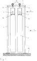
Figuren 1 bis 3 zeigen eine Flaschenbatterie 1 mit einzeln aufgehängten
Gasflaschen 6. Auf einem Boden 46 sind Stützen 4
und 5 aufgestellt, die mit einer Querstütze 3 verbunden sind.
Sammelrohre 2 liegen auf der Querstütze 3 auf und sind mit
dieser (nicht dargestellt) verbunden. An den Sammelrohren 2
sind die Gasflaschen 6 aufgehängt. Zu diesem Zweck ist eine
Befestigungeinrichtung 8 vorgesehen. Diese besteht aus einem,
auf einen Flaschenhals 19 der Gasflasche 6 aufgeschraubten
unteren Ringteller 9 mit zentraler Gewindebohrung
und einem oberenTeller 10. Die Teile 9 und 10 sind mit Abstand
mittels mehrerer Schraubbolzen 11 verbunden, die mit
dem Tellerring 9 fest verbunden sind. Das obere Ende der
Schraubbolzen 11 ist mit Gewinde versehen, die durch Bohrungen
des oberen Tellers 10 geführt und mittels Muttern 12 arretiert
sind. Mit dem oberen Teller 10 ist ein Verbindungsbolzen
17 mit Mutter befestigt, an den eine Wiegeeinrichtung 13 mit ihrem
unteren Teil angebracht ist. An der Oberseite der Wiegeeinrichtung
13 ist ein Haltebolzen 18 mit Mutter befestigt, an
den ein den unteren Teil des Sammelrohres 2 umfassendes
Klemmringteil 14 befestigt ist. Ein zweites Klemmringteil 15
umfaßt das Sammelrohr 2 von oben. Die beiden Klemmringe
14,15 werden mittels Schrauben mit Muttern 16 zusammengepreßt.
Damit hängt die Gasflasche 6 an dem Sammelrohr 2. Figures 1 to 3 show a
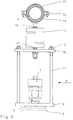
Figur 4 zeigt zwei, paarweise aufgehängte Gasflaschen 6. Dazu
ist eine auf den Boden 46 aufgestellte Stütze 5 vorgesehen,
die am Kopfende mit einem Befestigungskopf 31 versehen ist,
der mit dem Sammelrohr 2 verbunden ist. In diesem Ausführungsbeispiel
sind zwei Wiegeeinrichtungen 20 und 21 mit dem
Befestigungskopf 31 verbunden. An jeder dieser Wiegeeinrichtungen
20,21 hängt über eine Befestigungsvorrichtung 8 eine
Gasflasche 6.FIG. 4 shows two
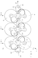
In Figur 5 sind drei Flaschenpaare 6/1, 6/2, 6/3 dargestellt, die
alle an ein Sammelrohr 2 aufgehängt sind. Dazu sind zwei
Stützen 5 vorgesehen, die an ihren Enden 2a und 2b jeweils
mit einem Tragekopf 22 verbunden sind. Die Gasflaschen 6a
und 6b eines Flaschenpaares 6/1 sind jeweils mittels eines
Befestigungskopfes 31 an dem Sammelrohr 2 aufgehängt. Für
eine Verbindung von den Ventilen 7 der Gasflaschen 6 zum
Sammelrohr 2 sind Verbindungsschläuche 44 und 45 vorgesehen.In Figure 5, three pairs of
Zur Vergrößerung einer Flaschenbatterie 1 können mehr als
drei Gasflaschen-Paare 6/1 an dem Sammelrohr 2 aufgehängt
werden. Entsprechend sind mehrere Stützen 5 mit Trageköpfen
22 vorzusehen. Außerdem können mehrere Reihen an Gasflaschen-Paare
nebeneinander aufgestellt werden, wobei jede
Gasflaschen-Paarreihe ein Sammelrohr 2 aufweist.To enlarge a
Der Tragekopf 22 gemäß Fig. 6 und 7 besteht aus einem Unterteil
23 mit einem Oberteil 24, die über einen Gelenkbolzen 25
gelenkig miteinander verbunden sind. Mit einer zentralen Ausnehmung
umfassen die Teile 23 und 24 das Sammelrohr 2 und
werden mittels einer Klemmschraube 26 und Klemmbolzen 26a
und 26b zusammengepreßt und so mit dem Sammelrohr 2 verbunden.
Das Unterteil 23 weist ein Stützelement 27 auf, mit der
der Trägerkopf 22 mit der Stütze 5 verbunden ist. An einer
Halteplatte 30 des Oberteils 24 ist mittels Schrauben 29 mit
Muttern eine Quertraverse 28 angebracht, mit der mehrere
Gasflaschen-Paarreihen miteinander verbunden werden können.
Auch kann die Quertraverse 28 für eine Wandbefestigung
verwendet werden.The carrying
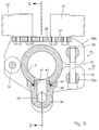
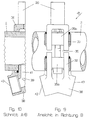
Der Befestigungskopf 31 gemäß Fig. 8 bis 10 besteht aus einem
Unterteil 32 mit einem Oberteil 33, die über einen Gelenkbolzen
34 gelenkig miteinander verbunden sind. Mit einer zentralen
Ausnehmung umfassen die Teile 32 und 33 das Sammelrohr
2 und werden mittels einer Klemmschraube 35 und
Klemmbolzen 35a und 35b zusammengepreßt und so mit dem
Sammelrohr 2 verbunden. Das Unterteil 32 weist ein mit einem
Kanal 39 versehenes Verbindungsteil 38 auf. Dieses ist mit einem
Zapfen 41 in die Bohrung 40 des Sammelrohres 2 eingeführt
und so mit dem Sammelrohr 2 verbunden. Ein Kragen 47
mit einem Dichtungsring 48 sorgen für eine einwandfreie Abdichtung.
Das Verbindungsteil 38 ist fernerhin mit zwei Anschlußstutzen
42 und 43 versehen, an die die Verbindungsschläuche
44 und 45 anschließbar sind. An einer Trageplatte
36 des Oberteils 33 sind mittels Schrauben 37 die Wiegeeinrichtungen
20 und 21 befestigt.The
Werden die Gasflaschen 6 einzeln aufgehängt, so wie in Figur
1 dargestellt, dann kann ein Befestigungskopf verwendet werden,
dessen Verbindungsteil 38 nur einen Anschlußstutzen 42
aufweist.If the
Claims (7)
dadurch gekennzeichnet,
daß die Gasflaschen (6) im Bereich des Flaschenhalses (19) mit einer Befestigungseinrichtung (8) versehen sind, die mittels einer elektronischen Wiegeeinrichtung (13;20,21) mit direktem Anschluß an die Brandmeldezentrale an mindestens einem auf Stützen (4,5) abgestützten Sammelrohr (2) aufgehängt sind, und daß die Flaschenventile (7) über Schläuche (44,45) mit dem Sammelrohr (2) verbunden sind.Bottle battery for a fire extinguishing system with high-pressure extinguishing gas filled in gas bottles (6), which is led from the valves (7) of the gas bottles via manifolds (2) to extinguishing valves, the gas bottles being controlled by a weighing control system using weighing devices (13; are connected,
characterized,
that the gas bottles (6) in the area of the bottle neck (19) are provided with a fastening device (8) which is connected to at least one on supports (4, 5) by means of an electronic weighing device (13; 20, 21) with a direct connection to the fire alarm control panel supported manifold (2) are suspended, and that the bottle valves (7) via hoses (44, 45) are connected to the manifold (2).
Applications Claiming Priority (2)
| Application Number | Priority Date | Filing Date | Title |
|---|---|---|---|
| DE19723556 | 1997-06-05 | ||
| DE1997123556 DE19723556B4 (en) | 1997-06-05 | 1997-06-05 | Fire extinguishing system |
Publications (2)
| Publication Number | Publication Date |
|---|---|
| EP0882470A2 true EP0882470A2 (en) | 1998-12-09 |
| EP0882470A3 EP0882470A3 (en) | 2000-04-12 |
Family
ID=7831464
Family Applications (1)
| Application Number | Title | Priority Date | Filing Date |
|---|---|---|---|
| EP98108699A Withdrawn EP0882470A3 (en) | 1997-06-05 | 1998-05-13 | Fire extinguishing plant |
Country Status (3)
| Country | Link |
|---|---|
| EP (1) | EP0882470A3 (en) |
| DE (1) | DE19723556B4 (en) |
| NO (1) | NO315499B1 (en) |
Cited By (3)
| Publication number | Priority date | Publication date | Assignee | Title |
|---|---|---|---|---|
| EP2796173A4 (en) * | 2011-12-20 | 2015-11-11 | Xi An J & R Fire Fighting Equipment Co Ltd | Fixed fire extinguishing apparatus |
| CN113399459A (en) * | 2021-06-17 | 2021-09-17 | 中色科技股份有限公司 | Carbon dioxide automatic inflation system for fire fighting of rolling mill |
| CN113588057A (en) * | 2021-07-21 | 2021-11-02 | 上海外高桥造船有限公司 | Gas cylinder support of weighing |
Families Citing this family (1)
| Publication number | Priority date | Publication date | Assignee | Title |
|---|---|---|---|---|
| DE202013008340U1 (en) | 2013-09-23 | 2013-11-27 | Minimax Mobile Services Gmbh & Co. Kg | Fire-extinguishing device and fire-fighting vehicle |
Citations (2)
| Publication number | Priority date | Publication date | Assignee | Title |
|---|---|---|---|---|
| CH183251A (en) * | 1935-07-24 | 1936-03-31 | Betzler Martin | Weighing device for continuous weight control of the contents of containers. |
| US5591943A (en) * | 1994-06-10 | 1997-01-07 | Cheng; Liang-Chieh | Weight-sensing member for an electrical suspension weigher |
Family Cites Families (2)
| Publication number | Priority date | Publication date | Assignee | Title |
|---|---|---|---|---|
| DE1291633B (en) * | 1964-04-08 | 1969-03-27 | Ceag Concordia Elek Zitaets Ag | Display device for carbon dioxide extinguishing systems |
| DE9212099U1 (en) * | 1992-09-08 | 1992-11-12 | G & S Brandschutz Gmbh, 5410 Hoehr-Grenzhausen, De |
-
1997
- 1997-06-05 DE DE1997123556 patent/DE19723556B4/en not_active Expired - Fee Related
-
1998
- 1998-05-13 EP EP98108699A patent/EP0882470A3/en not_active Withdrawn
- 1998-06-04 NO NO19982548A patent/NO315499B1/en not_active IP Right Cessation
Patent Citations (2)
| Publication number | Priority date | Publication date | Assignee | Title |
|---|---|---|---|---|
| CH183251A (en) * | 1935-07-24 | 1936-03-31 | Betzler Martin | Weighing device for continuous weight control of the contents of containers. |
| US5591943A (en) * | 1994-06-10 | 1997-01-07 | Cheng; Liang-Chieh | Weight-sensing member for an electrical suspension weigher |
Cited By (4)
| Publication number | Priority date | Publication date | Assignee | Title |
|---|---|---|---|---|
| EP2796173A4 (en) * | 2011-12-20 | 2015-11-11 | Xi An J & R Fire Fighting Equipment Co Ltd | Fixed fire extinguishing apparatus |
| US9750966B2 (en) | 2011-12-20 | 2017-09-05 | Xi'an Westpeace Fire Technology Co., Ltd | Fixed fire extinguishing apparatus |
| CN113399459A (en) * | 2021-06-17 | 2021-09-17 | 中色科技股份有限公司 | Carbon dioxide automatic inflation system for fire fighting of rolling mill |
| CN113588057A (en) * | 2021-07-21 | 2021-11-02 | 上海外高桥造船有限公司 | Gas cylinder support of weighing |
Also Published As
| Publication number | Publication date |
|---|---|
| EP0882470A3 (en) | 2000-04-12 |
| DE19723556B4 (en) | 2004-07-08 |
| NO315499B1 (en) | 2003-09-15 |
| DE19723556A1 (en) | 1998-12-10 |
| NO982548L (en) | 1998-12-07 |
| NO982548D0 (en) | 1998-06-04 |
Similar Documents
| Publication | Publication Date | Title |
|---|---|---|
| DE3531674C2 (en) | ||
| EP0396870B1 (en) | Weighing scales with protection against overload | |
| EP0342414B1 (en) | Clamp for in particular upright pipelines | |
| EP0133634B1 (en) | Clamping device | |
| EP0882470A2 (en) | Fire extinguishing plant | |
| DE202019003660U1 (en) | Device for lifting and fixing loads (e.g. two-wheelers) without drive and without its own energy supply, with plug-in connection for an external drive that can be adapted (plugged) onto / on the column construction and has an adjustable guide | |
| DE102010022440A1 (en) | Device for weighing | |
| DE3117158C2 (en) | "Device for monitoring the exhaust gas values of heating systems or the like." | |
| DE4025162A1 (en) | Pressure valves filling device - has cylinder movement stops, power supply interruption unit and endless arrangement | |
| AT391916B (en) | BOOM WITH HORIZONTAL ROPE TENSIONING | |
| EP1116499B1 (en) | Fire extinguishing plant with pressurized extinguishing gas | |
| DE3005599C2 (en) | Breathing air bottle connection for compressed air breathing apparatus | |
| EP2784386B1 (en) | Assembly for load measurement or adjusting the load | |
| DE19619779A1 (en) | Hospital gas supply system using bottles or cylinders | |
| DE3540266C1 (en) | Overload protection | |
| DE19539329C2 (en) | Compressed gas supply device for a vehicle | |
| DE4229095C2 (en) | Attachment for gas bottles | |
| DE2737960C2 (en) | Converter with a removable bottom | |
| DE2934373C2 (en) | Device for attaching electrical cables to a multiple insulator chain | |
| DE1083604B (en) | Overload break protection for tie rods with pressure nut, especially in stateless roll stands | |
| DE2244674B2 (en) | Force measuring device | |
| DE3533659A1 (en) | SCREW EXTENSION RACK | |
| DE19732862A1 (en) | Planarity measuring device for tensioned metal band | |
| AT201951B (en) | Device for the temporary connection of a branch line to a main line containing a pressure medium or a vacuum | |
| EP0028216B1 (en) | Supporting and guiding element for a continuous casting plant |
Legal Events
| Date | Code | Title | Description |
|---|---|---|---|
| PUAI | Public reference made under article 153(3) epc to a published international application that has entered the european phase |
Free format text: ORIGINAL CODE: 0009012 |
|
| AK | Designated contracting states |
Kind code of ref document: A2 Designated state(s): AT BE CH DE DK ES FI FR GB GR IE IT LI LU NL PT SE |
|
| AX | Request for extension of the european patent |
Free format text: AL;LT;LV;MK;RO;SI |
|
| PUAL | Search report despatched |
Free format text: ORIGINAL CODE: 0009013 |
|
| AK | Designated contracting states |
Kind code of ref document: A3 Designated state(s): AT BE CH CY DE DK ES FI FR GB GR IE IT LI LU MC NL PT SE |
|
| AX | Request for extension of the european patent |
Free format text: AL;LT;LV;MK;RO;SI |
|
| RIC1 | Information provided on ipc code assigned before grant |
Free format text: 7A 62C 37/50 A, 7G 01G 17/04 B, 7G 01G 19/18 B |
|
| 17P | Request for examination filed |
Effective date: 20000607 |
|
| AKX | Designation fees paid |
Free format text: AT BE CH DE DK ES FI FR GB GR IE IT LI LU NL PT SE |
|
| 17Q | First examination report despatched |
Effective date: 20040112 |
|
| GRAP | Despatch of communication of intention to grant a patent |
Free format text: ORIGINAL CODE: EPIDOSNIGR1 |
|
| STAA | Information on the status of an ep patent application or granted ep patent |
Free format text: STATUS: THE APPLICATION IS DEEMED TO BE WITHDRAWN |
|
| 18D | Application deemed to be withdrawn |
Effective date: 20050719 |