EP0881704A2 - Dispositif de radiocommunication dans un système de communication à AMDC avec calibration - Google Patents
Dispositif de radiocommunication dans un système de communication à AMDC avec calibration Download PDFInfo
- Publication number
- EP0881704A2 EP0881704A2 EP98109675A EP98109675A EP0881704A2 EP 0881704 A2 EP0881704 A2 EP 0881704A2 EP 98109675 A EP98109675 A EP 98109675A EP 98109675 A EP98109675 A EP 98109675A EP 0881704 A2 EP0881704 A2 EP 0881704A2
- Authority
- EP
- European Patent Office
- Prior art keywords
- transmit
- radio
- signal
- sections
- signals
- Prior art date
- Legal status (The legal status is an assumption and is not a legal conclusion. Google has not performed a legal analysis and makes no representation as to the accuracy of the status listed.)
- Withdrawn
Links
Images


Classifications
-
- H—ELECTRICITY
- H01—ELECTRIC ELEMENTS
- H01Q—ANTENNAS, i.e. RADIO AERIALS
- H01Q3/00—Arrangements for changing or varying the orientation or the shape of the directional pattern of the waves radiated from an antenna or antenna system
- H01Q3/26—Arrangements for changing or varying the orientation or the shape of the directional pattern of the waves radiated from an antenna or antenna system varying the relative phase or relative amplitude of energisation between two or more active radiating elements; varying the distribution of energy across a radiating aperture
- H01Q3/267—Phased-array testing or checking devices
-
- H—ELECTRICITY
- H04—ELECTRIC COMMUNICATION TECHNIQUE
- H04B—TRANSMISSION
- H04B1/00—Details of transmission systems, not covered by a single one of groups H04B3/00 - H04B13/00; Details of transmission systems not characterised by the medium used for transmission
- H04B1/69—Spread spectrum techniques
- H04B1/707—Spread spectrum techniques using direct sequence modulation
-
- H—ELECTRICITY
- H04—ELECTRIC COMMUNICATION TECHNIQUE
- H04B—TRANSMISSION
- H04B1/00—Details of transmission systems, not covered by a single one of groups H04B3/00 - H04B13/00; Details of transmission systems not characterised by the medium used for transmission
- H04B1/02—Transmitters
- H04B1/04—Circuits
-
- H—ELECTRICITY
- H04—ELECTRIC COMMUNICATION TECHNIQUE
- H04B—TRANSMISSION
- H04B17/00—Monitoring; Testing
- H04B17/10—Monitoring; Testing of transmitters
- H04B17/11—Monitoring; Testing of transmitters for calibration
- H04B17/14—Monitoring; Testing of transmitters for calibration of the whole transmission and reception path, e.g. self-test loop-back
-
- H—ELECTRICITY
- H04—ELECTRIC COMMUNICATION TECHNIQUE
- H04B—TRANSMISSION
- H04B7/00—Radio transmission systems, i.e. using radiation field
- H04B7/02—Diversity systems; Multi-antenna system, i.e. transmission or reception using multiple antennas
- H04B7/04—Diversity systems; Multi-antenna system, i.e. transmission or reception using multiple antennas using two or more spaced independent antennas
Definitions
- the present invention relates to digital mobile radio communication systems carrying out radio communications based on the CDMA (Code Division Multiple Access) system, or more specifically radio communication systems that calibrate radio transmit circuits by measuring the characteristics of radio transmit circuits.
- CDMA Code Division Multiple Access
- An array antenna system is known as an antenna system made up of a plurality of antennas.
- the array antenna system can freely set the transmit directivity by adjusting the amplitude and phase of signals sent from each antenna device.
- the amplitude and phase of the transmit signals can be adjusted at the transmit base band processing sections by multiplying the transmit signals by a complex coefficient.
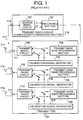
- FIG.1 shows a configuration of a CDMA radio communication system equipped with an array antenna that performs radio communications based on the CDMA system.
- the radio communication system in FIG. 1 shows an example of the array antenna system with three antenna devices.
- This communication system comprises transmit section 701, transmit base band processing sections 702, 703 and 704, calibration signal generators 705, 706 and 707, transmit radio circuits 708, 709 and 710, transmit terminals 711, 712 and 713, transmit antennas 714, 715 and 716, cable 717, transmit radio circuit characteristic measuring section 718, receive terminal 719, receive radio circuit 720 and demodulator 721.
- Radio transmit signals are generated by transmit section 701.
- transmit base band signals are generated by multiplying the information symbol signals to be transmitted by the same spreading code and further multiplying them by individually set complex coefficients.
- the transmit base band signals generated by transmit base band processing sections 702, 703 and 704 are up-converted to a radio frequency band, amplified and converted to radio transmit signals by transmit radio circuits 708, 709 and 710.
- the radio transmit signals go through transmit terminals 711, 712 and 713 and are transmitted from transmit antennas 714, 715 and 716.
- a shared antenna device may be used which serves as a transmit antenna device and receive antenna device simultaneously.
- adjusting the multiplication complex coefficients will allow the radiation field intensity to be increased in desired directions only. This is called “providing transmit directivity.” Providing transmit directivity will make it possible to keep receive SIR (Signal to Interference Ratio: hereafter referred to as SIR) of other communication systems high.
- SIR Signal to Interference Ratio
- transmit radio circuits 708, 709 and 710 differ from one circuit to another due to variations in the characteristics of devices such as amplifiers. This will add different unknown amplitude variations or phase rotations to the respective antenna transmit signals, forming a transmit directivity different from the transmit directivity expected to be obtained by multiplying a complex coefficient in transmit base band processing sections 702, 703 and 704.
- transmit radio circuits 708, 709 and 710 have the same characteristics.
- the method used here is to measure and store each of the characteristics of transmit radio circuits 708, 709 and 710 beforehand, and determine the complex coefficients by which transmit signals are multiplied in transmit base band processing sections 702, 703 and 704 taking into account the fact that the amplitude and phase of the transmit signals will change by the differences in their characteristics.
- Calibration signal generators 705, 706 and 707 generate calibration signals to measure the characteristics of the radio circuits. These generators generate sine wave signals with an extremely slow frequency, called tone signals, or time-invariable signals as the calibration signals.
- the present system provides either a separate transmit radio circuit characteristic measuring section or a receive section for communications.
- One of transmit radio circuits 708, 709 and 710 to be subjected to measurement of the transmit radio circuit characteristics is connected to transmit radio circuit characteristic measuring section 718 via cable 717 and the output signal of transmit radio circuit characteristic measuring section 718 is observed.
- Deviations of the amplitude and phase of the output signal of receive radio circuit 720 from expected values are stored as the differences contained in the characteristics of the transmit radio circuit in recording section 721.
- connection of transmit radio circuit characteristic measuring section 718 is switched to another transmit radio circuit to be subjected to characteristic measurement and the same processing is performed. The same procedure is repeated to all transmit radio circuits.
- transmit antennas 714, 715 and 716 are connected to transmit terminals 711, 712 and 713 and the system enters the communication mode.
- transmit base band processing sections 702, 703 and 704 use complex coefficients that are set to offset the recorded characteristic differences of the transmit radio circuits.
- the conventional radio communication system above uses tone signals as the calibration signals and the frequency bandwidth of those tone signals is very small compared with the frequency bandwidth of spreading signals for communication. This entails a problem that it is not possible to correctly measure the characteristics of transmit radio circuits when actually carrying out communications using spreading signals.
- the objective of the present invention is to accurately measure the characteristics of the transmit radio circuits when actually performing communications through spreading signals by using signals having the same bandwidth as that of spreading signals used for communications as the calibration signals.
- the present invention provides a CDMA radio communication apparatus that measures the characteristics of transmit radio circuits using calibration signals with a bandwidth equivalent to that of spreading signals used for communications.
- the base band processing sections of the CDMA radio communication apparatus can generate calibration signals having a bandwidth equivalent to that of spreading signals used for communications by multiplying respective transmit information symbol signals by different spreading codes.
- the calibration signals are passed through the transmit radio circuit sections in which the input signals are converted to radio transmit signals and a plurality of calibration signals output from each transmit radio circuit section are CDMA-multiplexed.
- the CDMA-multiplexed calibration signals are separately demodulated by different spreading codes.
- This configuration allows signals with the same bandwidth as that of spreading signals used for communications to be used as calibration signals, providing accurate measurement of the characteristics of transmit radio circuits.
- this configuration makes it possible to CDMA-multiplex all calibration signals output from the transmit radio circuit sections, input them to the receive radio circuits and demodulator, separate the calibration signals based on the correlation with spreading codes and measure their characteristics independently.
- FIG.2 shows a configuration of the CDMA radio communication apparatus related to a first embodiment. This is an example of the CDMA radio communication apparatus equipped with an array antenna comprising three antenna devices 111 to 113.
- Transmit section 101 is provided with the transmit base band processing sections (102, 103 and 104) and transmit radio circuits (105, 106 and 107) corresponding to three antenna devices 111 to 113, respectively. At the output ends of transmit radio circuits 105 to 107, transmit terminals 108, 109 and 110 are formed. Three antenna devices 111 to 113 are connected to these transmit terminals 108, 109 and 110.
- Cables 114, 115 and 116 can be connected to transmit terminals 108, 109 and 110.
- cables 114, 115 and 116 are connected to transmit terminals 108, 109 and 110.
- Cables 114, 115 and 116 connect transmit terminals 108 to 110 of transmit section 101 with addition section 117.
- Addition section 117 is connected to transmit radio circuit characteristic measuring section 119 via cable 118.
- Characteristic measuring section 119 has receive terminal 120 to which addition section 117 is connected via cable 118. Characteristic measuring section 119 is equipped with receive radio circuit 121, a plurality of demodulators 122, 123 and 124 and output interface 125.
- the CDMA radio communication apparatus configured as shown above operates as follows when communicating with other communication systems:
- Transmit base band processing sections 102, 103 and 104 in transmit section 101 generate transmit base band signals by multiplying the information symbol signals to be transmitted by the same spreading code and further multiplying them by individually set complex coefficients.
- the transmit base band signals generated by transmit base band processing sections 102, 103 and 104 are up-converted to a radio frequency band, and amplified and converted to radio transmit signals by transmit radio circuits 105, 106 and 107.
- the radio transmit signals are transmitted via corresponding transmit terminals 108, 109 and 110 from transmit antennas 111, 112 and 113.
- a shared antenna device may be used which serves as a transmit antenna device and receive antenna device simultaneously.
- adjusting the complex coefficients by which the transmit base band signals are multiplied and controlling the transmit directivity allow receive SIR of other communication stations to be increased.
- the characteristics of transmit radio circuits 105, 106 and 107 are measured before starting communications. Measurement of the characteristics of transmit radio circuits is explained below.
- all transmit base band processing sections 102, 103 and 104 In order to measure the characteristics of transmit radio circuits, all transmit base band processing sections 102, 103 and 104 generate transmit base band signals with known information symbols. Transmit base band processing sections 102, 103 and 104 obtain spread signals by multiplying the known symbol signals by different spreading codes. A plurality of these spread signals (base band signals) are input to corresponding transmit radio circuits 105, 106 and 107. The base band signals that have passed through transmit radio circuits 105, 106 and 107 are converted to transmit radio signals. These transmit radio signals created based on the base band signals are called calibration signals.
- Transmit radio circuits 105, 106 and 107 to be subjected to measurement of the characteristics of transmit radio circuits are connected to characteristic measuring section 119 via cables 114, 115 and 116, addition section 117 and cable 118. In this way the calibration signals are supplied from transmit section 101 to characteristic measuring section 119.
- cables 114, 115 and 116 are used to CDMA-multiplex a plurality of calibration signals and is hereafter referred to as a radio transmit signal synthesis section.
- CDMA multiplexing section multiplexing spread signals in the same frequency band.
- the calibration signals that have been CDMA-multiplexed by said radio transmit signal synthesis section are down-converted by receive radio circuit 121 and input to demodulators 122, 123 and 124.
- Demodulators 122, 123 and 124 separate the CDMA-multiplexed calibration signals and demodulate them separately based on the correlation between the CDMA-multiplexed calibration signals and spreading codes. These three demodulated signals retain the characteristics of their corresponding transmit radio circuits.
- This characteristic information is independently output from output interface 125.
- Output interface 125 can output the outputs of said demodulators 122, 123 and 124 as they are or by converting them in a different format.
- the demodulators are totally free to output the outputs of said demodulators; whether in a pair of the I component and Q component in the same format as that of the demodulators, or as a power which is a sum of squares of the I component and Q component, or as an amplitude by finding the square root of them, or as a phase by finding the inverse tangent of the I component and Q component.
- the configuration above allows the characteristics of all the transmit radio circuits (105, 106 and 107) to be measured simultaneously, without the need to change cables connections during the measurement. This solves the following problems of the conventional array antenna communication systems unable to perform simultaneous characteristic measurements of a plurality of transmit radio circuits:
- Transmit radio circuits 708, 709 and 710 subject to characteristic measurements and receive radio circuit 720 incorporated in transmit radio circuit characteristic measuring section 718 each have a separate local oscillator.
- the output phase of these local oscillators changes, the output phase of the radio circuits also changes. Since there are subtle differences in the oscillation frequencies of these local oscillators, the output phase of each local oscillator changes every moment independently. Under such circumstances, even if the characteristics of the radio circuits are constant, the measurement results from transmit radio circuit characteristic measuring section 718 change every moment, which makes the characteristics of the radio circuits appear changing every moment.
- transmit radio circuits 708, 709 and 710 in transmit section 701 use local oscillators with the same frequency, it is possible to provide only one local oscillator and share its output with all transmit radio circuits 708, 709 and 710. This makes it possible to keep differences between the output signals of different transmit radio circuits invariable with time.
- the local oscillation frequency in receive radio circuit 720 and the local oscillation frequency in transmit radio circuits 708, 709 and 710 are not always designed to be the same. If the transmit radio circuits and receive radio circuit have different local oscillation frequencies, transmit radio circuits 708, 709 and 710 and receive radio circuit 720 must have separate local oscillators.
- the measurement results from transmit radio circuit characteristic measuring section 718 change every moment, making the delay characteristic of the radio circuits appear changing every moment.
- the characteristics of each transmit radio circuit measured at different times may contain unrecognizable measurement differences, rendering the characteristic measurement meaningless.
- the present embodiment CDMA-multiplexes all calibration signals output from a plurality of transmit radio circuits 105 to 107 and inputs the resultant signals to transmit radio circuit characteristic measuring section 119, where the calibration signals are separated based on the correlation with spreading codes and their characteristics are measured separately.
- This allows the characteristics of all transmit radio circuits 105 to 107 to be measured simultaneously. This also eliminates the necessity of frequently changing cable connections for characteristic measurements.
- transmit radio circuits 105 to 107 and receive radio circuit 121 of transmit radio circuit characteristic measurement section 119 cannot use a common local oscillator, it provides accurate measurement of the characteristics of transmit radio circuits 105 to 107.
- the present embodiment allows signals with the same bandwidth as that of spreading signals used for communications to be used as calibration signals, providing high accuracy measurement of the characteristics of transmit radio circuits. It also eliminates the necessity of frequently changing cable connections for characteristic measurements and furthermore provides more accurate measurements of the characteristics of transmit radio circuits even if no common local oscillators are available for the transmit radio circuits and receive radio circuit in the transmit radio circuit characteristic measuring section.
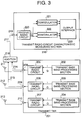
- FIG. 3 shows a configuration of the CDMA radio communication system related to a second embodiment of the present invention.
- Embodiment 2 comprises an array antenna containing three antenna devices, 2 demodulators in the transmit radio circuit characteristic measuring section to measure the amount of delay of the transmit radio circuits.
- Transmit section 201 comprises transmit base band processing sections 202, 203 and 204, transmit radio circuits 205, 206 and 207, transmit terminals 208, 209 and 210 and antenna devices 211, 212 and 213.
- Two transmit terminals 208 and 209 are connected with addition section 216 via cables 214 and 215 and addition section 216 is further connected with transmit radio circuit characteristic measuring section 218 via cable 217.
- Characteristic measuring section 218 is connected to cable 217 through receive terminal 219. Characteristic measuring section 218 is equipped with receive radio circuit 220, demodulators 221 and 222 and output interface 223.
- Transmit base band processing sections 202, 203 and 204 in transmit section 201 generate transmit base band signals by multiplying the information symbol signals to be transmitted by the same spreading code and further multiplying the spread spectrum transmit signals by individually set complex coefficients.
- the transmit base band signals generated by transmit base band processing sections 202, 203 and 204 are each up-converted to a radio frequency band, amplified and converted to radio transmit signals by corresponding transmit radio circuits 205, 206 and 207.
- the radio transmit signals go through transmit terminals 208, 209 and 210 and are transmitted from antenna devices 211, 212 and 213.
- a shared antenna device may be used which serves as a transmit antenna device and receive antenna device simultaneously.
- adjusting the complex coefficients by which the transmit base band signals are multiplied provides the system with transmit directivity, making it possible to keep receive SIR of other communication systems high.
- transmit radio circuits 205, 206 and 207 in transmit section 201 are generally measured before starting communications. Measurement of the characteristics of transmit radio circuits is explained below.
- all transmit base band processing sections 202, 203 and 204 In order to measure the characteristics of transmit radio circuits 205 to 207, all transmit base band processing sections 202, 203 and 204 generate transmit base band signals with known information symbols.
- the radio transmit signals created based on these base band signals are particularly called calibration signals.
- the transmit radio circuits to be subjected to measurement of the characteristics of transmit radio circuits are selected from transmit radio circuits 205, 206 and 207 (FIG.3 shows the case where transmit radio circuits 205 and 206 are selected) and transmit terminals 208 and 209 of the selected transmit radio circuits 205 and 206 are connected to addition section 216 via cables 214 and 215, and the output of the addition section is input to receive terminal 219 of characteristic measuring section 218 via cable 217.
- the system made up of these cables 214 and 215, addition section 216 and cable 217 is used to CDMA-multiplex a plurality of calibration signals and is called a radio transmit signal synthesis section.
- first demodulator 221 demodulates the calibration signal generated by first transmit radio circuit 205
- second demodulator 222 demodulates the calibration signal generated by second transmit radio circuit 206.
- the differences of the characteristics between first transmit radio circuit 205 and second transmit radio circuit 206 are calculated based on the two measurement results output from output interface 223.
- first demodulator 221 demodulates the calibration signal generated by first transmit radio circuit 205 and second demodulator 222 demodulates the calibration signal generated by third transmit radio circuit 207.
- the differences of the characteristics between first transmit radio circuit 205 and third transmit radio circuit 207 are calculated based on the two measurement results output from output interface 223.
- the characteristics of different transmit radio circuits are measured in a plurality of different time zones, and if different local oscillators are used in the transmit radio circuits and receive radio circuit in the characteristic measuring section, the absolute values of the measured characteristics have no meaning.
- all transmit radio circuits 205 to 207 use a common local oscillator and relative characteristic differences between transmit radio circuits 205 to 207 are fixed, and thus the characteristic differences measured using a one transmit radio circuit (first transmit radio circuit 205 in the example above) as a reference are quite accurate.
- Output interface 223 can output the outputs of demodulators 221 and 222 above as they are or by converting them in a different format. For example, it is totally free to output the outputs of said demodulators; whether in a pair of the I component and Q component in the same format as that of the demodulators, or as a power which is a sum of squares of the I component and Q component, or as an amplitude by finding the square root of them, or as a phase by finding the inverse tangent of the I component and Q component.
- the present embodiment uses less demodulators in the transmit radio circuit characteristic measuring section than the transmit radio circuits and despite the fact that it takes more time and is more troublesome than the system having the same number of demodulators, it can reduce the scale of the system, making it possible to keep the measuring accuracy quite high.
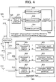
- FIG. 4 shows a configuration of the CDMA radio communication system related to a third embodiment of the present invention.
- Embodiment 3 is an example of the case where the function of the characteristic measuring section in Embodiment 1 above is assumed by the receive section that receives and processes radio signals from other communication systems.
- Transmit section 301 of this CDMA radio communication system comprises transmit base band processing sections 302, 303 and 304, transmit radio circuits 305, 306 and 307, transmit terminals 308, 309 and 310 and transmit antennas 311, 312 and 313.
- Transmit terminal 308, 309 and 310 are connected with addition section 317 via cables 314, 315 and 316 and addition section 317 is further connected with receive section 319 via cable 318.
- Receive section 319 can be used as the transmit radio circuit characteristic measuring section described in Embodiment 1.
- Receive terminal 320 of this receive section 319 is connected with cable 318 which is connected with addition section 317 and receive antenna 326.
- cable 318 is connected with receive terminal 320.
- Receive section 319 is equipped with receive radio circuit 321, demodulators 322, 323 and 324 and output interface 325.
- the CDMA radio communication system When communicating with other communication systems, the CDMA radio communication system configured as shown above operates as follows: Transmit base band processing sections 302, 303 and 304 in transmit section 301 generate transmit base band signals by multiplying the information symbol signals to be transmitted by the same spreading code and further multiplying them by individually set complex coefficients.
- the transmit base band signals generated by transmit base band processing sections 302, 303 and 304 are up-converted to a radio frequency band, amplified and converted to radio transmit signals by transmit radio circuits 305, 306 and 307.
- the radio transmit signals go through transmit terminals 308, 309 and 310 and are transmitted from antennas 311, 312 and 313.
- adjusting the complex coefficients by which the transmit base band signals are multiplied provides the system with transmit directivity, making it possible to keep receive SIR of other communication systems high.
- radio signals transmitted from other communication systems When radio signals transmitted from other communication systems are received, these radio signals are received from receive antenna 326 connected to receive terminal 320 of receive section 319.
- the signals received are down-converted by receive radio circuit 321 and demodulated by one of demodulators 322, 323 and 324.
- transmit radio circuits 305, 306 and 307 in transmit section 301 are measured before starting communications. Measurement of the characteristics of transmit radio circuits is explained below.
- all transmit base band processing sections 302, 303 and 304 In order to measure the characteristics of transmit radio circuits, all transmit base band processing sections 302, 303 and 304 generate transmit base band signals with known information symbols.
- the radio transmit signals created based on these transmit base band signals are particularly called calibration signals.
- Transmit terminals 308 to 310 of transmit section 301 are connected to receive terminal 320 of receive section 319.
- transmit radio circuits 305, 306 and 307 subject to measurement of the characteristics of transmit radio circuits are connected to addition section 317 via cables 314, 315 and 316 and the output of the addition section is supplied to receive terminal 320 of transmit radio circuit characteristic measuring section 319 via cable 318.
- cables 314, 315 and 316 it is important to adjust cables 314, 315 and 316 so that the differences in their lengths be small enough for the wavelength of the radio transmit signals.
- the system made up of these cables 314, 315 and 316, addition section 317 and cable 318 is used to CDMA-multiplex a plurality of calibration signals and is called a radio transmit signal synthesis section.
- the calibration signals that have been CDMA-multiplexed by said radio transmit signal synthesis section are separated by demodulators 322, 323 and 324 and demodulated separately based on the correlation with spreading codes and output from output interface 325.
- Output interface 325 can output the outputs of said demodulators 322, 323 and 324 as they are or by converting them in a different format.
- the demodulators are totally free to output the outputs of said demodulators; whether in a pair of the I component and Q component in the same format as that of the demodulators, or as a power which is a sum of squares of the I component and Q component, or as an amplitude by finding the square root of them, or as a phase by finding the inverse tangent of the I component and Q component.
- radio section 319 assumes the function of measuring transmit radio circuit characteristics, allowing radio signals from other communication systems to be received in communication mode, without the need to provide any dedicated transmit radio circuit characteristic measuring section.
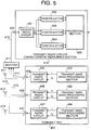
- FIG.5 shows a configuration of the CDMA radio communication system related to a fourth embodiment of the present invention.
- Embodiment 4 is an example of the case of Embodiments 1 to 3 plus a recording section to store the characteristic data of the measured transmit radio circuits.
- Transmit section 401 has the same configuration as that of said Embodiment 1. That is, transmit section 401 comprises transmit base band processing sections 402, 403 and 404, transmit radio circuits 405, 406 and 401, transmit terminals 408, 409 and 410 and antenna devices 411, 412 and 413.
- Transmit terminals 408, 409 and 410 are connected with addition section 417 via cables 414, 415 and 416, and addition section 417 is further connected with transmit radio circuit characteristic measuring section 419 via cable 418.
- Cable 418 is connected to receive terminal 420 of transmit radio circuit characteristic measuring section 419.
- Characteristic measuring section 419 is equipped with receive radio circuit 421, demodulators 422,423 and 424 and recording section 425.
- the CDMA radio communication system of Embodiment 4 consists of the system of either Embodiment 1 or Embodiment 3 plus a recording section to store the measured characteristic data.
- This recording section can also be configured with memory. The rest of the configuration and operation are the same as those of said embodiments.
- the present embodiment allows the characteristic data of the transmit radio circuits that can be measured by the array antenna radio CDMA communication system to be recorded and used for various types of processing.
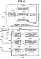
- FIG.6 shows a configuration of the CDMA radio communication system related to a fifth embodiment of the present invention.
- the present embodiment is an example of the case where the characteristic data recorded in the recording section in Embodiment 4 is fed back to the transmit section to be used for directivity control of antennas.
- the rest of the configuration and operation are the same as those of the CDMA radio communication system in Embodiment 4 described above.
- the characteristics of all transmit radio circuits 505 to 507 are measured and stored in recording section 525 of characteristic measuring section 519.
- transmit section 501 Based on the transmit radio circuit characteristic data, transmit section 501 can control processing at transmit base band sections 502, 503 and 504 so as to offset characteristic differences between transmit radio circuits 505, 506 and 507, making it possible to accurately achieve the desired transmit directivity.
- FIG.7 shows a section diagram of the CDMA radio communication system related to a sixth embodiment of the present invention.
- the present embodiment shows an example of the case where the transmit radio circuits in the transmit section and receive radio circuit in the receive section (or characteristic measuring section) are designed to use common local oscillation frequencies.
- Transmit section 601 comprises transmit base band processing sections 602, 603 and 604, transmit radio circuits 605, 606 and 607, transmit terminals 608, 609 and 610, and transmit antennas 611, 612 and 613. Transmit section 601 can be connected with receive section 615 via cable 614.
- Transmit radio circuit characteristic measuring section 615 comprises receive terminal 616, receive radio circuit 617, demodulator 618, and recording section 619.
- transmit base band processing sections 602, 603 and 604 in transmit section 601 When communicating with other communication systems, transmit base band processing sections 602, 603 and 604 in transmit section 601 generate transmit base band signals by multiplying the information symbol signals to be transmitted by the same spreading code and further multiplying them by individually set complex coefficients.
- the transmit base band signals generated by transmit base band processing sections 602, 603 and 604 are up-converted to a radio frequency band, amplified and converted to radio transmit signals by transmit radio circuits 605, 606 and 607.
- the radio transmit signals go through transmit terminals 608, 609 and 610 and are transmitted from transmit antennas 611, 612 and 613.
- a shared antenna device may be used which serves as a transmit antenna device and receive antenna device simultaneously.
- adjusting the complex coefficients by which the transmit base band signals are multiplied allows the transmission field density to be increased only in a desired direction. Providing the system with transmit directivity makes it possible to keep receive SIR of other communication systems high.
- the measuring mode is implemented before starting communications. Measurement of the characteristics of transmit radio circuits is explained below.
- all transmit base band processing sections 602, 603 and 604 In order to measure the characteristics of transmit radio circuits, all transmit base band processing sections 602, 603 and 604 generate transmit base band signals with known information symbols.
- the radio transmit signals created based on these base band signals are particularly called calibration signals.
- transmit radio circuit characteristic measuring section either a separate transmit radio circuit characteristic measuring section or a communication receive section is provided.
- One of transmit radio circuits 605, 606 and 607 subject to transmit radio circuit characteristic measurement is connected to the transmit radio circuit characteristic measuring section via cable 614 and the output signal of transmit radio circuit characteristic measuring section 615 is observed. Deviations of the amplitude and phase of the output signal of transmit radio circuit characteristic measuring section 615 from the expected values are recorded as the characteristic differences of the transmit radio circuit. Then, connection of transmit radio circuit characteristic measuring section 615 is switched to another transmit radio circuit subject to characteristic measurement and the same processing is performed. The same procedure is repeated to all transmit radio circuits.
- transmit antennas 611, 612 and 613 are connected to transmit terminals 608, 609 and 610 and the system enters the communication mode.
- transmit base band processing sections 602, 603 and 604 use complex coefficients that are set to offset the recorded characteristic differences of the transmit radio circuits.
- receive radio circuit 617 and transmit radio circuits 605, 606 and 607 are designed to have the same local oscillation frequencies, it is possible to use the same local oscillator for receive radio circuit 617 and transmit radio circuits 605, 606 and 607. In a system configuration having a common local oscillator, it is possible to prevent time variations of the results of transmit radio circuit characteristic measurement arising from oscillation frequency differences between local oscillators.
- the configuration above allows high accuracy measurement of the characteristics of transmit radio circuits without the necessity of providing a plurality of demodulators in the transmit radio circuit characteristic measuring section.
- the present invention allows the use of signals with the same bandwidth as that of spreading signals used for communications as the calibration signals, providing high accuracy measurement of the characteristics of transmit radio circuits.
Landscapes
- Engineering & Computer Science (AREA)
- Computer Networks & Wireless Communication (AREA)
- Signal Processing (AREA)
- Physics & Mathematics (AREA)
- Electromagnetism (AREA)
- Mobile Radio Communication Systems (AREA)
- Radio Transmission System (AREA)
- Radio Relay Systems (AREA)
- Variable-Direction Aerials And Aerial Arrays (AREA)
- Monitoring And Testing Of Transmission In General (AREA)
- Traffic Control Systems (AREA)
Applications Claiming Priority (3)
| Application Number | Priority Date | Filing Date | Title |
|---|---|---|---|
| JP9155779A JPH10336149A (ja) | 1997-05-28 | 1997-05-28 | アレーアンテナ無線cdma通信装置 |
| JP15577997 | 1997-05-28 | ||
| JP155779/97 | 1997-05-28 |
Publications (2)
| Publication Number | Publication Date |
|---|---|
| EP0881704A2 true EP0881704A2 (fr) | 1998-12-02 |
| EP0881704A3 EP0881704A3 (fr) | 2000-10-18 |
Family
ID=15613234
Family Applications (1)
| Application Number | Title | Priority Date | Filing Date |
|---|---|---|---|
| EP98109675A Withdrawn EP0881704A3 (fr) | 1997-05-28 | 1998-05-27 | Dispositif de radiocommunication dans un système de communication à AMDC avec calibration |
Country Status (4)
| Country | Link |
|---|---|
| EP (1) | EP0881704A3 (fr) |
| JP (1) | JPH10336149A (fr) |
| KR (1) | KR100268748B1 (fr) |
| CN (1) | CN1200605A (fr) |
Cited By (12)
| Publication number | Priority date | Publication date | Assignee | Title |
|---|---|---|---|---|
| EP1003310A1 (fr) * | 1998-06-18 | 2000-05-24 | Matsushita Electric Industrial Co., Ltd. | Dispositif d'etalonnage |
| WO2000074265A1 (fr) | 1999-05-28 | 2000-12-07 | Matsushita Electric Industrial Co., Ltd. | Dispositif et procede de communication |
| EP1085684A2 (fr) * | 1999-09-14 | 2001-03-21 | Hitachi, Ltd. | Unité d'antenne et station de base radio |
| EP1093186A1 (fr) * | 1999-03-31 | 2001-04-18 | Matsushita Electric Industrial Co., Ltd. | Radioemetteur et procede de reglage de la directivite d'emission |
| WO2001031744A1 (fr) * | 1999-10-26 | 2001-05-03 | Siemens Aktiengesellschaft | Procede pour le calibrage d'une antenne de groupe a commande de phase electronique dans des systemes de communication radio |
| EP1120858A2 (fr) * | 1999-12-15 | 2001-08-01 | Nippon Telegraph and Telephone Corporation | Emetteur-récepteur avec réseau d'antennes |
| EP1161002A1 (fr) * | 2000-01-13 | 2001-12-05 | Matsushita Electric Industrial Co., Ltd. | Appareil de communication radio a antenne reseau et procede d'etalonnage |
| EP1162763A1 (fr) * | 2000-01-17 | 2001-12-12 | Matsushita Electric Industrial Co., Ltd. | Etalonneur intermittent |
| EP1178562A1 (fr) * | 2000-08-03 | 2002-02-06 | Telefonaktiebolaget L M Ericsson (Publ) | Etallonage d'un réseau d'antennes |
| EP1416655A2 (fr) * | 2002-10-30 | 2004-05-06 | Nec Corporation | Réseau d'antennes émetteur-récepteur et procédé de calibrage du chemin de transmission utilisée pour ce système |
| WO2009019526A1 (fr) * | 2007-08-09 | 2009-02-12 | Nokia Corporation | Étalonnage de systèmes d'antennes intelligentes |
| EP2040333A1 (fr) * | 2007-09-24 | 2009-03-25 | Astrium GmbH | Procédé et dispositif d'étalonnage d'une antenne de réseau |
Families Citing this family (14)
| Publication number | Priority date | Publication date | Assignee | Title |
|---|---|---|---|---|
| GB2342505B (en) * | 1998-10-06 | 2003-06-04 | Telecom Modus Ltd | Antenna array calibration |
| US6327299B1 (en) * | 1999-08-31 | 2001-12-04 | Motorola, Inc. | Method and system for measuring and adjusting the quality of an orthogonal transmit diversity signal in a wireless communications system |
| JP2001267990A (ja) | 2000-03-21 | 2001-09-28 | Matsushita Electric Ind Co Ltd | アレイアンテナ基地局装置 |
| JP2002353865A (ja) * | 2001-05-23 | 2002-12-06 | Nec Corp | アレーアンテナ送受信装置及びそのキャリブレーション方法 |
| JP3651430B2 (ja) | 2001-09-17 | 2005-05-25 | 日本電気株式会社 | アレーアンテナの校正装置及び校正方法 |
| JP4098027B2 (ja) | 2002-08-01 | 2008-06-11 | 松下電器産業株式会社 | 無線基地局装置 |
| JP4252573B2 (ja) * | 2003-06-02 | 2009-04-08 | 富士通株式会社 | アレーアンテナ通信装置およびアレーアンテナ通信装置のキャリブレーション方法 |
| JP4384892B2 (ja) * | 2003-10-27 | 2009-12-16 | 株式会社日立国際電気 | 無線通信装置 |
| JP2006005525A (ja) | 2004-06-16 | 2006-01-05 | Nec Corp | 送信装置 |
| KR100706229B1 (ko) * | 2004-12-21 | 2007-04-11 | 삼성전자주식회사 | 내장된 송수신기들 간의 반송파 주파수 차를 보상하는다중 송수신 시스템 및 그 방법 |
| JP5186748B2 (ja) * | 2006-09-29 | 2013-04-24 | 富士通株式会社 | 無線通信装置および無線通信方法 |
| KR100986189B1 (ko) * | 2010-08-23 | 2010-10-07 | 엘아이지넥스원 주식회사 | 신호 복원 장치 및 그 방법 |
| US8736481B2 (en) * | 2011-10-28 | 2014-05-27 | Texas Instruments Incorporated | Carrier frequency offset compensation in beamforming systems |
| US9584231B2 (en) * | 2014-10-30 | 2017-02-28 | Samsung Electronics Co., Ltd. | Integrated two dimensional active antenna array communication system |
Citations (4)
| Publication number | Priority date | Publication date | Assignee | Title |
|---|---|---|---|---|
| US5029181A (en) * | 1989-07-17 | 1991-07-02 | Kyocera Corporation | Automatic calibration device for direct spectrum spread receiver |
| EP0642191A1 (fr) * | 1993-09-03 | 1995-03-08 | Matra Marconi Space Uk Limited | Dispositif numérique de formation de faisceaux d'antennes pour véhicule spatial |
| WO1997000543A1 (fr) * | 1995-06-16 | 1997-01-03 | Watkins-Johnson Company | Procede et appareil de formation de faisceau d'emission adaptative dans un systeme de communications sans fils |
| EP0938204A1 (fr) * | 1997-03-18 | 1999-08-25 | Matsushita Electric Industrial Co., Ltd. | Dispositif d'etalonnage pour recepteur sans fil d'antenne reseau |
Family Cites Families (1)
| Publication number | Priority date | Publication date | Assignee | Title |
|---|---|---|---|---|
| JPH03165103A (ja) * | 1989-11-22 | 1991-07-17 | Nec Corp | アレーアンテナ位相校正装置 |
-
1997
- 1997-05-28 JP JP9155779A patent/JPH10336149A/ja active Pending
-
1998
- 1998-05-27 EP EP98109675A patent/EP0881704A3/fr not_active Withdrawn
- 1998-05-28 KR KR1019980019437A patent/KR100268748B1/ko not_active IP Right Cessation
- 1998-05-28 CN CN98109624A patent/CN1200605A/zh active Pending
Patent Citations (4)
| Publication number | Priority date | Publication date | Assignee | Title |
|---|---|---|---|---|
| US5029181A (en) * | 1989-07-17 | 1991-07-02 | Kyocera Corporation | Automatic calibration device for direct spectrum spread receiver |
| EP0642191A1 (fr) * | 1993-09-03 | 1995-03-08 | Matra Marconi Space Uk Limited | Dispositif numérique de formation de faisceaux d'antennes pour véhicule spatial |
| WO1997000543A1 (fr) * | 1995-06-16 | 1997-01-03 | Watkins-Johnson Company | Procede et appareil de formation de faisceau d'emission adaptative dans un systeme de communications sans fils |
| EP0938204A1 (fr) * | 1997-03-18 | 1999-08-25 | Matsushita Electric Industrial Co., Ltd. | Dispositif d'etalonnage pour recepteur sans fil d'antenne reseau |
Non-Patent Citations (1)
| Title |
|---|
| PATENT ABSTRACTS OF JAPAN vol. 015, no. 405 (E-1122), 16 October 1991 (1991-10-16) & JP 03 165103 A (NEC CORP), 17 July 1991 (1991-07-17) * |
Cited By (36)
| Publication number | Priority date | Publication date | Assignee | Title |
|---|---|---|---|---|
| EP1003310A1 (fr) * | 1998-06-18 | 2000-05-24 | Matsushita Electric Industrial Co., Ltd. | Dispositif d'etalonnage |
| EP1003310A4 (fr) * | 1998-06-18 | 2005-06-01 | Matsushita Electric Ind Co Ltd | Dispositif d'etalonnage |
| EP1093186A1 (fr) * | 1999-03-31 | 2001-04-18 | Matsushita Electric Industrial Co., Ltd. | Radioemetteur et procede de reglage de la directivite d'emission |
| EP1093186A4 (fr) * | 1999-03-31 | 2004-07-07 | Matsushita Electric Ind Co Ltd | Radioemetteur et procede de reglage de la directivite d'emission |
| EP1102418A1 (fr) * | 1999-05-28 | 2001-05-23 | Matsushita Electric Industrial Co., Ltd. | Dispositif et procede de communication |
| EP1102418A4 (fr) * | 1999-05-28 | 2008-04-02 | Matsushita Electric Ind Co Ltd | Dispositif et procede de communication |
| WO2000074265A1 (fr) | 1999-05-28 | 2000-12-07 | Matsushita Electric Industrial Co., Ltd. | Dispositif et procede de communication |
| US6647276B1 (en) | 1999-09-14 | 2003-11-11 | Hitachi, Ltd. | Antenna unit and radio base station therewith |
| US7203462B2 (en) | 1999-09-14 | 2007-04-10 | Hitachi Ltd | Antenna unit and radio base station therewith |
| EP1085684A2 (fr) * | 1999-09-14 | 2001-03-21 | Hitachi, Ltd. | Unité d'antenne et station de base radio |
| US7587174B2 (en) | 1999-09-14 | 2009-09-08 | Hitachi, Ltd. | Antenna unit and radio base station therewith |
| EP1085684A3 (fr) * | 1999-09-14 | 2003-05-28 | Hitachi, Ltd. | Unité d'antenne et station de base radio |
| WO2001031744A1 (fr) * | 1999-10-26 | 2001-05-03 | Siemens Aktiengesellschaft | Procede pour le calibrage d'une antenne de groupe a commande de phase electronique dans des systemes de communication radio |
| DE19951525A1 (de) * | 1999-10-26 | 2001-06-07 | Siemens Ag | Verfahren zum Kalibrieren einer elektronisch phasengesteuerten Gruppenantenne in Funk-Kommunikationssystemen |
| DE19951525C2 (de) * | 1999-10-26 | 2002-01-24 | Siemens Ag | Verfahren zum Kalibrieren einer elektronisch phasengesteuerten Gruppenantenne in Funk-Kommunikationssystemen |
| EP2139069A3 (fr) * | 1999-12-15 | 2010-03-03 | Nippon Telegraph and Telephone Corporation | Appareil émetteur-récepteur doté d'une antenne réseau adaptative |
| EP2139068A3 (fr) * | 1999-12-15 | 2010-03-03 | Nippon Telegraph and Telephone Corporation | Appareil émetteur-récepteur doté d'une antenne réseau adaptative |
| EP1120858A3 (fr) * | 1999-12-15 | 2005-05-04 | Nippon Telegraph and Telephone Corporation | Emetteur-récepteur avec réseau d'antennes |
| EP2139071A3 (fr) * | 1999-12-15 | 2010-03-03 | Nippon Telegraph and Telephone Corporation | Appareil émetteur-récepteur doté d'une antenne réseau adaptative |
| EP2139070A3 (fr) * | 1999-12-15 | 2010-03-03 | Nippon Telegraph and Telephone Corporation | Appareil émetteur-récepteur doté d'une antenne réseau adaptative |
| EP1777838A2 (fr) * | 1999-12-15 | 2007-04-25 | Nippon Telegraph and Telephone Corporation | Appareil émetteur-récepteur doté d'une antenne réseau adaptative |
| EP1120858A2 (fr) * | 1999-12-15 | 2001-08-01 | Nippon Telegraph and Telephone Corporation | Emetteur-récepteur avec réseau d'antennes |
| EP1777838A3 (fr) * | 1999-12-15 | 2008-10-22 | Nippon Telegraph and Telephone Corporation | Appareil émetteur-récepteur doté d'une antenne réseau adaptative |
| US6559799B2 (en) * | 2000-01-13 | 2003-05-06 | Matsushita Electric Industrial Co., Ltd. | Array antenna radio communication apparatus and calibration method |
| EP1161002A4 (fr) * | 2000-01-13 | 2006-06-07 | Matsushita Electric Ind Co Ltd | Appareil de communication radio a antenne reseau et procede d'etalonnage |
| EP1161002A1 (fr) * | 2000-01-13 | 2001-12-05 | Matsushita Electric Industrial Co., Ltd. | Appareil de communication radio a antenne reseau et procede d'etalonnage |
| EP1162763A1 (fr) * | 2000-01-17 | 2001-12-12 | Matsushita Electric Industrial Co., Ltd. | Etalonneur intermittent |
| US6970497B2 (en) | 2000-01-17 | 2005-11-29 | Matsushita Electric Industrial Co., Ltd. | Intermittent calibration apparatus |
| EP1162763A4 (fr) * | 2000-01-17 | 2003-04-23 | Matsushita Electric Ind Co Ltd | Etalonneur intermittent |
| EP1178562A1 (fr) * | 2000-08-03 | 2002-02-06 | Telefonaktiebolaget L M Ericsson (Publ) | Etallonage d'un réseau d'antennes |
| EP1416655A2 (fr) * | 2002-10-30 | 2004-05-06 | Nec Corporation | Réseau d'antennes émetteur-récepteur et procédé de calibrage du chemin de transmission utilisée pour ce système |
| EP1416655A3 (fr) * | 2002-10-30 | 2010-05-05 | Nec Corporation | Réseau d'antennes émetteur-récepteur et procédé de calibrage du chemin de transmission utilisée pour ce système |
| WO2009019526A1 (fr) * | 2007-08-09 | 2009-02-12 | Nokia Corporation | Étalonnage de systèmes d'antennes intelligentes |
| EP2040333A1 (fr) * | 2007-09-24 | 2009-03-25 | Astrium GmbH | Procédé et dispositif d'étalonnage d'une antenne de réseau |
| WO2009040038A1 (fr) * | 2007-09-24 | 2009-04-02 | Astrium Gmbh | Procédé et dispositif pour étalonner une antenne réseau |
| US8674874B2 (en) | 2007-09-24 | 2014-03-18 | Astrium Gmbh | Method and device for calibrating an array antenna |
Also Published As
| Publication number | Publication date |
|---|---|
| CN1200605A (zh) | 1998-12-02 |
| KR100268748B1 (ko) | 2000-10-16 |
| EP0881704A3 (fr) | 2000-10-18 |
| JPH10336149A (ja) | 1998-12-18 |
| KR19980087443A (ko) | 1998-12-05 |
Similar Documents
| Publication | Publication Date | Title |
|---|---|---|
| EP0881704A2 (fr) | Dispositif de radiocommunication dans un système de communication à AMDC avec calibration | |
| KR100913883B1 (ko) | 스마트 안테나의 출력 신호 왜곡 측정 및 보상 장치 및 방법 | |
| KR100614432B1 (ko) | 어레이 안테나 교정 장치 및 어레이 안테나 교정 방법 | |
| US6647276B1 (en) | Antenna unit and radio base station therewith | |
| EP2139070B1 (fr) | Appareil émetteur-récepteur doté d'une antenne réseau adaptative | |
| US6157343A (en) | Antenna array calibration | |
| KR100363367B1 (ko) | 무선 통신 장치 및 송신 전력 제어 방법 | |
| EP0938204A1 (fr) | Dispositif d'etalonnage pour recepteur sans fil d'antenne reseau | |
| US6448939B2 (en) | Array antenna receiving apparatus | |
| US6594509B1 (en) | Array-antenna radio communication apparatus | |
| JP3519276B2 (ja) | キャリブレーション装置 | |
| JP3546773B2 (ja) | アンテナ・アレイの校正方法及び装置 | |
| KR20010074768A (ko) | 통신 장치 및 통신 방법 | |
| US5710977A (en) | Apparatus for measuring multipath propagation characteristics | |
| US6847803B1 (en) | Method for reducing interference in a receiver | |
| US6385441B1 (en) | Array antenna radio communication apparatus | |
| US6529163B2 (en) | Array antenna radio communication apparatus and array antenna radio communication method | |
| JP2000286629A (ja) | 無線送信装置及び送信指向性調整方法 | |
| JP4578725B2 (ja) | 通信装置およびその送信アレーアンテナ校正方法 | |
| US7233811B2 (en) | Radio device with transmission directivity, and control method and control program for the radio device | |
| US20090046814A1 (en) | In-phase signal and quadrature signal generator of multi-port network | |
| WO2002082679A1 (fr) | Recepteur d'antenne reseau |
Legal Events
| Date | Code | Title | Description |
|---|---|---|---|
| PUAI | Public reference made under article 153(3) epc to a published international application that has entered the european phase |
Free format text: ORIGINAL CODE: 0009012 |
|
| AK | Designated contracting states |
Kind code of ref document: A2 Designated state(s): DE FI FR GB |
|
| AX | Request for extension of the european patent |
Free format text: AL;LT;LV;MK;RO;SI |
|
| PUAL | Search report despatched |
Free format text: ORIGINAL CODE: 0009013 |
|
| AK | Designated contracting states |
Kind code of ref document: A3 Designated state(s): AT BE CH CY DE DK ES FI FR GB GR IE IT LI LU MC NL PT SE |
|
| AX | Request for extension of the european patent |
Free format text: AL;LT;LV;MK;RO;SI |
|
| 17P | Request for examination filed |
Effective date: 20001123 |
|
| AKX | Designation fees paid |
Free format text: DE FI FR GB |
|
| 17Q | First examination report despatched |
Effective date: 20050330 |
|
| STAA | Information on the status of an ep patent application or granted ep patent |
Free format text: STATUS: THE APPLICATION IS DEEMED TO BE WITHDRAWN |
|
| 18D | Application deemed to be withdrawn |
Effective date: 20051210 |