EP0880423B1 - Cutting die and method of forming - Google Patents
Cutting die and method of forming Download PDFInfo
- Publication number
- EP0880423B1 EP0880423B1 EP97908663A EP97908663A EP0880423B1 EP 0880423 B1 EP0880423 B1 EP 0880423B1 EP 97908663 A EP97908663 A EP 97908663A EP 97908663 A EP97908663 A EP 97908663A EP 0880423 B1 EP0880423 B1 EP 0880423B1
- Authority
- EP
- European Patent Office
- Prior art keywords
- blade
- die
- blades
- cylinder
- shaping
- Prior art date
- Legal status (The legal status is an assumption and is not a legal conclusion. Google has not performed a legal analysis and makes no representation as to the accuracy of the status listed.)
- Expired - Lifetime
Links
Images
Classifications
-
- B—PERFORMING OPERATIONS; TRANSPORTING
- B23—MACHINE TOOLS; METAL-WORKING NOT OTHERWISE PROVIDED FOR
- B23P—METAL-WORKING NOT OTHERWISE PROVIDED FOR; COMBINED OPERATIONS; UNIVERSAL MACHINE TOOLS
- B23P15/00—Making specific metal objects by operations not covered by a single other subclass or a group in this subclass
- B23P15/28—Making specific metal objects by operations not covered by a single other subclass or a group in this subclass cutting tools
- B23P15/40—Making specific metal objects by operations not covered by a single other subclass or a group in this subclass cutting tools shearing tools
- B23P15/406—Making specific metal objects by operations not covered by a single other subclass or a group in this subclass cutting tools shearing tools rotary or plane die cutters
-
- B—PERFORMING OPERATIONS; TRANSPORTING
- B23—MACHINE TOOLS; METAL-WORKING NOT OTHERWISE PROVIDED FOR
- B23K—SOLDERING OR UNSOLDERING; WELDING; CLADDING OR PLATING BY SOLDERING OR WELDING; CUTTING BY APPLYING HEAT LOCALLY, e.g. FLAME CUTTING; WORKING BY LASER BEAM
- B23K26/00—Working by laser beam, e.g. welding, cutting or boring
- B23K26/20—Bonding
- B23K26/32—Bonding taking account of the properties of the material involved
-
- B—PERFORMING OPERATIONS; TRANSPORTING
- B23—MACHINE TOOLS; METAL-WORKING NOT OTHERWISE PROVIDED FOR
- B23K—SOLDERING OR UNSOLDERING; WELDING; CLADDING OR PLATING BY SOLDERING OR WELDING; CUTTING BY APPLYING HEAT LOCALLY, e.g. FLAME CUTTING; WORKING BY LASER BEAM
- B23K26/00—Working by laser beam, e.g. welding, cutting or boring
- B23K26/34—Laser welding for purposes other than joining
-
- B—PERFORMING OPERATIONS; TRANSPORTING
- B23—MACHINE TOOLS; METAL-WORKING NOT OTHERWISE PROVIDED FOR
- B23K—SOLDERING OR UNSOLDERING; WELDING; CLADDING OR PLATING BY SOLDERING OR WELDING; CUTTING BY APPLYING HEAT LOCALLY, e.g. FLAME CUTTING; WORKING BY LASER BEAM
- B23K35/00—Rods, electrodes, materials, or media, for use in soldering, welding, or cutting
- B23K35/001—Interlayers, transition pieces for metallurgical bonding of workpieces
-
- B—PERFORMING OPERATIONS; TRANSPORTING
- B23—MACHINE TOOLS; METAL-WORKING NOT OTHERWISE PROVIDED FOR
- B23K—SOLDERING OR UNSOLDERING; WELDING; CLADDING OR PLATING BY SOLDERING OR WELDING; CUTTING BY APPLYING HEAT LOCALLY, e.g. FLAME CUTTING; WORKING BY LASER BEAM
- B23K35/00—Rods, electrodes, materials, or media, for use in soldering, welding, or cutting
- B23K35/02—Rods, electrodes, materials, or media, for use in soldering, welding, or cutting characterised by mechanical features, e.g. shape
- B23K35/0222—Rods, electrodes, materials, or media, for use in soldering, welding, or cutting characterised by mechanical features, e.g. shape for use in soldering, brazing
- B23K35/0244—Powders, particles or spheres; Preforms made therefrom
-
- C—CHEMISTRY; METALLURGY
- C21—METALLURGY OF IRON
- C21D—MODIFYING THE PHYSICAL STRUCTURE OF FERROUS METALS; GENERAL DEVICES FOR HEAT TREATMENT OF FERROUS OR NON-FERROUS METALS OR ALLOYS; MAKING METAL MALLEABLE, e.g. BY DECARBURISATION OR TEMPERING
- C21D9/00—Heat treatment, e.g. annealing, hardening, quenching or tempering, adapted for particular articles; Furnaces therefor
- C21D9/18—Heat treatment, e.g. annealing, hardening, quenching or tempering, adapted for particular articles; Furnaces therefor for knives, scythes, scissors, or like hand cutting tools
-
- B—PERFORMING OPERATIONS; TRANSPORTING
- B23—MACHINE TOOLS; METAL-WORKING NOT OTHERWISE PROVIDED FOR
- B23K—SOLDERING OR UNSOLDERING; WELDING; CLADDING OR PLATING BY SOLDERING OR WELDING; CUTTING BY APPLYING HEAT LOCALLY, e.g. FLAME CUTTING; WORKING BY LASER BEAM
- B23K2103/00—Materials to be soldered, welded or cut
- B23K2103/50—Inorganic material, e.g. metals, not provided for in B23K2103/02 – B23K2103/26
-
- C—CHEMISTRY; METALLURGY
- C21—METALLURGY OF IRON
- C21D—MODIFYING THE PHYSICAL STRUCTURE OF FERROUS METALS; GENERAL DEVICES FOR HEAT TREATMENT OF FERROUS OR NON-FERROUS METALS OR ALLOYS; MAKING METAL MALLEABLE, e.g. BY DECARBURISATION OR TEMPERING
- C21D1/00—General methods or devices for heat treatment, e.g. annealing, hardening, quenching or tempering
- C21D1/06—Surface hardening
- C21D1/09—Surface hardening by direct application of electrical or wave energy; by particle radiation
-
- C—CHEMISTRY; METALLURGY
- C21—METALLURGY OF IRON
- C21D—MODIFYING THE PHYSICAL STRUCTURE OF FERROUS METALS; GENERAL DEVICES FOR HEAT TREATMENT OF FERROUS OR NON-FERROUS METALS OR ALLOYS; MAKING METAL MALLEABLE, e.g. BY DECARBURISATION OR TEMPERING
- C21D6/00—Heat treatment of ferrous alloys
- C21D6/04—Hardening by cooling below 0 degrees Celsius
Definitions
- This invention relates to cutting dies and, in particular, to the manufacture of dies for cutting various stock materials.
- a method comprising the steps of the preamble of claim 1 is known from US-A-39 52 179.
- Cutting dies are known for cutting or severing one portion of a stock material from another.
- cutting dies are used for cutting sheets of paperboard or plastic or metal into predetermined blanks.
- two rotary cylinders each having small integral cutting blades extending radially from the cylindrical surface, are juxtaposed so that when rotated, the blades engage generally opposite sides of a work stock and cooperate to sever the stock into a blank, the shape of which is determined by the blade configuration.
- U.S. Patent No. 4,608,905 incorporated herein by reference.
- each cylindrical die requires certain process treatments to insure the blades will provide the desired cutting action over a long operational life. Specifically, the blades must be very hard in order to provide sufficient blade life before reconditioning is required.
- an entire die cylinder of appropriate size is heat-treated to bring the cylinder's surface to a requisite hardness, on the order, for example of about HRC 60 on the Rockwell hardness scale. Since the blades are formed integrally from the cylinder, the next process is to remove cylinder material to form and define the integral blades which are to extend radially outwardly from the cylinder's surface. While it might be possible to mill the surface down to form the blades, the hardness of the cylinder makes milling a bad choice.
- EDM electro discharge machining
- the difficulty faced by a die manufacturer is the conflict between the need for hard blades for die life and the preferability of soft surface material for formation of the die blades.
- a slow, expensive and capital intensive EDM process is required to form the blades. If the blades are first milled, and then the cylinder heated and cooled to harden the blades, distortion and cracking may result.
- One difficulty in that process is that of annealing portions of previously-hardened intersecting blades and thus causing a soft spot in such blades which might reduce die life or the functional time between blade reconditioning.
- a further objective of the invention has been to provide a process for making a cutting die which process allows for the selection of material based on desired blade parameters and life without unduly increasing the cost of the die.
- U.S. Patent No. 3952179 describes a rotary cutting die formed by applying a weld bead on the peripheral surface of a blank and then machining to form the cutting edges.
- a method of forming a cutting die in accordance with the invention comprises cladding a blade material onto a die surface to form a blade extending outwardly from the surface, and shaping the cladded blade, characterised in that the method includes the further step of cryogenic treating the blade.
- the process for forming a cutting die includes scanning a die surface with a laser through a desired blade pattern, introducing selected powder into the area being scanned by the laser beam to build up an integral blade along the scan pattern and thereafter forming the final shape of the blade by milling, grinding, electric discharge machining (EDM) or other suitable process.
- the formed blade may then additionally be heat treated and/or cryogenic treated, if required.
- the blade is formed preferably in one laser pass wherein a blade height of about two millimeters is produced. Additional passes might be used where higher blades are desired.
- lasers of higher power can be used to build higher blades in a single pass, but the cost of higher powered lasers than that necessary for a two millimeter blade height, can be prohibitive.
- Such a cladding process as is described above provides numerous advantages in forming cutting dies.
- the materials for the die blades and for the die cylinder can be selected respectively based on the varied parameters of each, such as blade hardness and life on the one hand, and die cylinder toughness on the other, without the huge cost increases when the entire die body must be of the selected blade material.
- the process produces a metallurgical bonding of powdered blade material to the die body material.
- a metallurgical bonding of powdered blade material to the die body material is much more secure than a mechanical bond as might result from conventional surface coating techniques, and essentially produces a die blade of high grade material integrally with a die body of lower grade, less costly material.
- the blade may be finally shaped by any suitable technique, such as by EDM or by grinding or by milling.
- EDM shaping is preferred.
- the final shaping process is relatively quicker and less costly. Only very small portions of the formed blade need be removed to form the final, preferably tapered blade shape with each side inclined about 25° to 35 °, and no cylinder material need be removed to define the blade.
- this cladding process produces a distinct blade feature on a die cylinder or body, useful as a cutting blade.
- the powdered material may be D-2 steel or a higher grade, such as CMP10V or CMP15V I, for example, for producing a very hard, long-life blade. It is not necessary, however, to use such high grade material in the die cylinder or body, which can be made of 4150 or even 1045 steel, for example sufficient to provide a strong die body. Material cost is substantially reduced while, at the same time, blade performance and life is substantially increased. Blade material is selected based on blade performance criteria while die body material is selected based on die body parameters, yet an integral cutting die is formed at a lower material cost than previously attainable when enhanced blade life is desired.
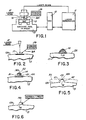
- a CO 2 laser head 10 and generator 11, controlled by a CNC 12, are operationally interconnected.
- a CO 2 laser head 10 and laser generator 11 can be, for example, the laser components manufactured by TRUMPF, Incorporated of Farmington, Connecticut according to its model no. TLF 2600 turbo.
- the path and density of laser beam can be controlled by the CNC 12.
- One such CNC is made by Boston Digital Corp. of Boston, Massachusetts under the model no. BD85-2.
- the die is mounted on a three, and preferably four, axis machine tool 15.
- One such machine tool is made by Boston Digital Corp. under the model no. BD85-2.
- Powder feeder 16 can be either a side feeder or coaxial feeder which is preferable.
- a side feeder is manufactured by Sulzer Metco (Wostbury, Inc) of Cincinnati, Ohio under model METCO Type 9MP.
- a die cylinder 13 is shown with the blade 14 being formed therein.
- the die cylinder is rotated by the machine tool 15, which is also controlled by the CNC machine 12 to coordinate with the laser head 10 and the laser generator 11.
- the powder feeder 16 is associated with the laser head 10, so as to selectively introduce powder into the area being clad, as will be described.
- Fig. 2 there is illustrated a part of the process of the invention.
- the laser beam 10 is scanned along the die surface 13A, so as to melt or "puddle" an area 17 in the surface 13A, along a path corresponding to the desired die blade pattern.
- the powder 16A is fed into the area being clad by the laser so that in one pass along the surface 13A, as illustrated in Fig. 13, a die blade of half ellipse cross-sectional dimension is formed.
- the material of the die body 13 is selected to conform to the desired parameters in the die body for toughness. Ordinary, medium carbon plain steels or medium carbon low alloy steels such as 1045 or 4150 steel, for example, may be used.
- the material which is preferably introduced in powder form, to form the blade 14 may be of another material selected based on the desired parameters of the die blade.
- This material can be a very high grade steel, such as CMP10V or CMP15V, or a metal-ceramic composite, such as a nickel base superalloy plus 30-40% (volume fraction) tungsten carbides.
- the deposition of powder through a powder nozzle forms a generally half ellipse cross-sectional die blade 14 as illustrated in Fig. 3. It is preferable to have the final die blade in a cross-sectional profile with edges which are somewhat tapered such as, for example, at about 25° to about 35°.
- Such die blade shapes for example, are disclosed in U.S. Patent No. 4,608,895, which render the die blades suitable for contact with an opposing die for cutting a work piece inserted therebetween.
- Fig. 4 illustrates the desired final shape of the die blade 14.
- Fig. 4 it will be appreciated that areas 21, 22 and 23 have been removed from the die blade 14, so the die blade 14 is of tapered or truncated configuration in cross-section.
- the die blade may be desirable to further harden the die blade and this may be accomplished by any suitable technique, such as by raising the die blade material to a temperature sufficient for further strengthening that material and/or by cryogenic treating the clad tracks to eliminate the remaining austenite in the cladding material.
- the die blade could be treated by scanning a laser beam along the die blades where the parameter of the traverse speed and intensity are appropriate to produce the optimum microstructures and hardness. It will be appreciated, however, that by virtue of the use of very high quality steel in the forming of the blade, such as those mentioned above, the optional heat treating steps for strengthening die blade may be unnecessary. Alternatively, localized hardening might be accomplished by induction heating.
- the final shape and size of the die blade are important.
- the die blade must be high enough to provide the desired cutting of the desired workpiece. For many applications, it has been found that a die blade of approximately 1.5 to 2.0 millimeters is high enough for a large number and variety of applications.
- the top surface 14A of the die blade As shown in Fig. 4, will be approximately 0.889 mm (.035 inches) wide. Such a die blade would be suitable for rotary pressure cuts, for example.
- the width of the die blade top 14A may be, for example, 0.0254 - 0.0508 mm (0.001-0.002 inches).
- the final shaping of the die blade may be carried out by any suitable process. It is preferred to use an electronic discharge machine (EDM) process to remove the small amount of material necessary on each side of the die blades.
- EDM electronic discharge machine
- the die blades could be ground or milled into the desired shape.
- the phantom line 25 is used to contrast the process of the invention with prior processes where the die blades were formed integrally from the die body.
- a die body may have had an outer periphery 25.
- the starting material is a die body 13 having a surface 13A and that the die blade 14 is built up as a feature on the die surface 13A. It is thus not necessary to start with a cylinder having a periphery such as 25 and then grind or remove away the material illustrated between the surface 13A and the phantom line 25. Instead, the only shaping required is as illustrated in Fig. 4, where final shaping of the sides of the die blade is performed with only material designated at 21, 22 and 23 being removed. It will also be appreciated that, as contrasted with the prior processes, the die blade 14 can be formed of any suitable materials, based on the desired parameters for the die blade itself, and is not necessarily the same material as the die body.
- a laser of approximately two kilowatt or above is useful in cladding or building up the die blade material.
- Die blades of approximately two millimeters or somewhat greater in height may be produced in a single pass with such a laser. It would be possible to build up the die blades by multiple laser passes assuming, of course, that the intersections of the various layers did not present a usage or a wear problem in the final die blade.
- the laser generation medium is not limited to CO 2 gas. Any other types of lasers which use different mediums could also be applied if they can generate enough power.
- the blades can be built up via cladding using a heating source (laser beam) and a cladding material supply (powder).
- the heating source which is used to melt cladding material and die surface is not limited to lasers. Any other heating sources which can quickly raise temperature on the selected area could be used in this invention, for example, thermal spraying gun, ion beam, electron beam and plasma transfer arc, etc.
- the cladding materials are not limited to powder. For example, welding wire, gaseous materials, liquid materials, might be used without departing from the scope of the invention.
Applications Claiming Priority (3)
| Application Number | Priority Date | Filing Date | Title |
|---|---|---|---|
| US60237996A | 1996-02-16 | 1996-02-16 | |
| US602379 | 1996-02-16 | ||
| PCT/US1997/002482 WO1997029879A1 (en) | 1996-02-15 | 1997-02-14 | Cutting die and method of forming |
Publications (2)
| Publication Number | Publication Date |
|---|---|
| EP0880423A1 EP0880423A1 (en) | 1998-12-02 |
| EP0880423B1 true EP0880423B1 (en) | 2001-11-28 |
Family
ID=24411119
Family Applications (1)
| Application Number | Title | Priority Date | Filing Date |
|---|---|---|---|
| EP97908663A Expired - Lifetime EP0880423B1 (en) | 1996-02-16 | 1997-02-14 | Cutting die and method of forming |
Country Status (12)
| Country | Link |
|---|---|
| US (1) | US7827883B1 (da) |
| EP (1) | EP0880423B1 (da) |
| JP (1) | JP2001525732A (da) |
| CN (1) | CN1071168C (da) |
| AT (1) | ATE209551T1 (da) |
| AU (1) | AU2051797A (da) |
| CA (1) | CA2245864C (da) |
| DE (1) | DE69708604T2 (da) |
| DK (1) | DK0880423T3 (da) |
| ES (1) | ES2166980T3 (da) |
| HK (1) | HK1026663A1 (da) |
| WO (1) | WO1997029879A1 (da) |
Families Citing this family (32)
| Publication number | Priority date | Publication date | Assignee | Title |
|---|---|---|---|---|
| GB2365026B (en) * | 2000-05-25 | 2004-08-18 | Infraco Bcv Ltd | Coating of rails |
| DE10317579B4 (de) * | 2003-04-16 | 2016-04-14 | Lasertec Gmbh | Verfahren und Vorrichtung zur Herstellung eines Gesenks in einem Werkstück |
| PL1725363T3 (pl) * | 2004-02-18 | 2011-05-31 | Soc Dexploitation Tarrerias Bonjean | Sposób wytwarzania ostrza tnącego |
| GB201001000D0 (en) * | 2010-01-22 | 2010-03-10 | Rolls Royce Plc | Method of forming a hollow component with an internal structure |
| ES2618914T3 (es) * | 2011-03-04 | 2017-06-22 | Nv Bekaert Sa | Método para producir un perla de aserrado |
| TWI583808B (zh) * | 2011-11-02 | 2017-05-21 | 國立中央大學 | 金屬玻璃及金屬玻璃合金鍍膜切割器具銳度提升之應用 |
| JP5871230B2 (ja) * | 2011-12-27 | 2016-03-01 | 公立大学法人 滋賀県立大学 | 切っ先部を備える工具、切っ先部を備える工具の製造方法、及び切っ先部を備える工具の製造中間体の製造方法 |
| US10462963B2 (en) | 2012-03-06 | 2019-11-05 | Kondex Corporation | Laser clad cutting edge for agricultural cutting components |
| EP2822727A4 (en) * | 2012-03-06 | 2015-10-21 | Kondex Corp | LASER VENEER CUTTING EDGE FOR AGRICULTURAL CUTTING COMPONENTS |
| CN104245224B (zh) * | 2012-04-16 | 2017-11-10 | 麦格纳国际公司 | 用于激光辅助的工具构造和修复的方法 |
| US9833785B2 (en) | 2012-12-17 | 2017-12-05 | Kooima Company | Method of making a processor disk |
| ITPD20130237A1 (it) * | 2013-08-28 | 2015-03-01 | Mico Group S R L | Metodo per la realizzazione di utensili per macchine atte alla formatura di filettature su corpi cilindrici mediante deformazione plastica |
| US10124531B2 (en) | 2013-12-30 | 2018-11-13 | Ut-Battelle, Llc | Rapid non-contact energy transfer for additive manufacturing driven high intensity electromagnetic fields |
| JP6341730B2 (ja) * | 2014-04-07 | 2018-06-13 | 三菱日立パワーシステムズ株式会社 | パウダ供給ヘッドの管理方法、エロージョンシールドの形成方法、及び装置 |
| US9650537B2 (en) | 2014-04-14 | 2017-05-16 | Ut-Battelle, Llc | Reactive polymer fused deposition manufacturing |
| EP3142475A4 (en) | 2014-05-12 | 2018-01-17 | Kondex Corporation | Slicing disc mower knives |
| EP3142476B1 (en) | 2014-05-12 | 2020-08-12 | Kondex Corporation | Cutting blade with transverse hardened regions |
| US9717176B2 (en) | 2014-09-15 | 2017-08-01 | Kondex Corporation | Agricultural blades and machine parts with amorphous metal laser cladding |
| CN104668769B (zh) * | 2015-02-10 | 2017-03-01 | 江苏大学 | 一种可变式复杂模具表面的激光自动冲击装置及方法 |
| US10648051B2 (en) | 2015-04-24 | 2020-05-12 | Kondex Corporation | Reciprocating cutting blade with cladding |
| US20160325380A1 (en) * | 2015-05-08 | 2016-11-10 | Dm3D Technology, Llc | Hybrid manufacturing using metal forming and additive manufacturing |
| US10717129B2 (en) * | 2015-06-23 | 2020-07-21 | Halliburton Energy Services, Inc. | Pre-diffused mandrel coating to provide enhanced bonding between metallic and composite components |
| AT15071U1 (de) * | 2015-11-04 | 2016-12-15 | Gebrüder Busatis Gesellschaft M B H | Zerkleinerungszahnscheibe für einen Körnerprozessor |
| US20170130285A1 (en) * | 2015-11-10 | 2017-05-11 | Caterpillar Inc. | Method for processing a metal component |
| DE102016004657B4 (de) * | 2016-04-16 | 2018-05-09 | J.G. WEISSER SöHNE GMBH & CO. KG | Verfahren zum Einrichten einer Drehbearbeitungsmaschine und Drehbearbeitungsmaschine |
| FR3060426B1 (fr) * | 2016-12-19 | 2019-01-25 | Peugeot Citroen Automobiles Sa | Procede d’emboutissage et decoupe en serie |
| DE102017121526A1 (de) * | 2017-09-15 | 2019-03-21 | Rollomatic S.A. | Vorrichtung zur Ausrichtung und Positionierung eines Werkstücks relativ zu einem Laserstrahl einer Laserbearbeitungsmaschine |
| CN108588566B (zh) * | 2018-06-20 | 2020-06-30 | 华东交通大学 | 一种FexWyC-贝氏体成分和组织双重梯度复合材料 |
| US20200130220A1 (en) * | 2018-10-31 | 2020-04-30 | Stolle Machinery Company, Llc | Score die, score die forming system, and associated method |
| CN110340198A (zh) * | 2019-06-28 | 2019-10-18 | 鑫佰图科技(惠州)有限公司 | 散热鳍片及散热鳍片的加工方法 |
| WO2021084727A1 (ja) * | 2019-10-31 | 2021-05-06 | 株式会社Ibuki | 金型の補修方法および金型 |
| CN112975147B (zh) * | 2021-02-07 | 2021-09-14 | 深圳市海特联科科技有限公司 | 一种激光切割压电二氧化硅工艺 |
Family Cites Families (27)
| Publication number | Priority date | Publication date | Assignee | Title |
|---|---|---|---|---|
| US3063310A (en) * | 1959-10-15 | 1962-11-13 | Continental Machines | Metal cutting saw bands and blades and method of making the same |
| US3240914A (en) * | 1962-11-28 | 1966-03-15 | Gen Motors Corp | Method of making dies |
| US3905283A (en) * | 1974-05-08 | 1975-09-16 | Rockwell International Corp | Improved rotary cutting die |
| US3952179A (en) * | 1974-05-08 | 1976-04-20 | Rockwell International Corporation | Rotary cutting die and method for its production |
| GB1522509A (en) * | 1976-01-14 | 1978-08-23 | British Steel Corp | Manufacture of metallic strip |
| DE2907325A1 (de) * | 1979-02-24 | 1980-09-04 | Winkler Duennebier Kg Masch | Schneidwalze zur erzeugung profilierter innen-und aussenschnitte |
| US4323756A (en) * | 1979-10-29 | 1982-04-06 | United Technologies Corporation | Method for fabricating articles by sequential layer deposition |
| US4383784A (en) * | 1980-01-07 | 1983-05-17 | Precision Twist Drill & Machine Co. | Method and means of manufacturing a rotary cutting tool |
| US4299860A (en) * | 1980-09-08 | 1981-11-10 | The United States Of America As Represented By The Secretary Of The Navy | Surface hardening by particle injection into laser melted surface |
| JPS5758990A (en) * | 1980-09-26 | 1982-04-09 | Toshiba Corp | Die |
| US4837417A (en) * | 1983-12-05 | 1989-06-06 | Funk Charles F | Method of hard-facing a metal surface |
| US4608895A (en) * | 1984-03-14 | 1986-09-02 | Bernal Rotary Systems, Inc. | Rotary die cutting |
| US4745256A (en) * | 1985-02-12 | 1988-05-17 | Metallurgical Industries, Inc. | Narrow substrate having weld bead of powdered metal |
| JPS62224527A (ja) * | 1986-03-25 | 1987-10-02 | Daido Steel Co Ltd | 工具の製造方法 |
| JPS6340621A (ja) * | 1986-08-05 | 1988-02-22 | Honda Motor Co Ltd | トリミング用鋳造金型およびその製造方法 |
| US4927992A (en) * | 1987-03-04 | 1990-05-22 | Westinghouse Electric Corp. | Energy beam casting of metal articles |
| US4864094A (en) * | 1988-01-13 | 1989-09-05 | Metallurgical Industries, Inc. | Process of fabricating a cutting edge on a tool and a cutting tool made thereby |
| JP2582326B2 (ja) * | 1991-11-27 | 1997-02-19 | 本田技研工業株式会社 | プレス金型の製造方法 |
| US5361968A (en) * | 1992-08-14 | 1994-11-08 | Honda Giken Kogyo Kabushiki Kaisha | Method of manufacturing metallic press die |
| US5449536A (en) * | 1992-12-18 | 1995-09-12 | United Technologies Corporation | Method for the application of coatings of oxide dispersion strengthened metals by laser powder injection |
| US5417132A (en) * | 1993-01-19 | 1995-05-23 | Alan R. Pfaff | Rotary cutting dies |
| JPH06297055A (ja) * | 1993-04-16 | 1994-10-25 | Honda Motor Co Ltd | プレス金型の製造方法 |
| US5448035A (en) * | 1993-04-28 | 1995-09-05 | Advanced Surfaces And Processes, Inc. | Method and apparatus for pulse fusion surfacing |
| FR2707677B1 (fr) * | 1993-07-13 | 1995-08-25 | Technogenia | Plaque de défibrage ou de raffinage de pâte à papier, et procédé pour sa réalisation. |
| US6122564A (en) * | 1998-06-30 | 2000-09-19 | Koch; Justin | Apparatus and methods for monitoring and controlling multi-layer laser cladding |
| US6146476A (en) * | 1999-02-08 | 2000-11-14 | Alvord-Polk, Inc. | Laser-clad composite cutting tool and method |
| US7139633B2 (en) * | 2002-08-29 | 2006-11-21 | Jyoti Mazumder | Method of fabricating composite tooling using closed-loop direct-metal deposition |
-
1997
- 1997-02-14 CA CA002245864A patent/CA2245864C/en not_active Expired - Lifetime
- 1997-02-14 EP EP97908663A patent/EP0880423B1/en not_active Expired - Lifetime
- 1997-02-14 AU AU20517/97A patent/AU2051797A/en not_active Abandoned
- 1997-02-14 WO PCT/US1997/002482 patent/WO1997029879A1/en active IP Right Grant
- 1997-02-14 AT AT97908663T patent/ATE209551T1/de not_active IP Right Cessation
- 1997-02-14 CN CN97193102A patent/CN1071168C/zh not_active Expired - Lifetime
- 1997-02-14 DE DE69708604T patent/DE69708604T2/de not_active Expired - Lifetime
- 1997-02-14 DK DK97908663T patent/DK0880423T3/da active
- 1997-02-14 ES ES97908663T patent/ES2166980T3/es not_active Expired - Lifetime
- 1997-02-14 JP JP52956297A patent/JP2001525732A/ja not_active Ceased
-
1998
- 1998-09-25 US US09/160,991 patent/US7827883B1/en not_active Expired - Fee Related
-
2000
- 2000-01-06 HK HK00100092A patent/HK1026663A1/xx not_active IP Right Cessation
Also Published As
| Publication number | Publication date |
|---|---|
| WO1997029879A1 (en) | 1997-08-21 |
| CA2245864A1 (en) | 1997-08-21 |
| AU2051797A (en) | 1997-09-02 |
| US7827883B1 (en) | 2010-11-09 |
| DK0880423T3 (da) | 2002-02-11 |
| HK1026663A1 (en) | 2000-12-22 |
| CA2245864C (en) | 2005-03-29 |
| ATE209551T1 (de) | 2001-12-15 |
| EP0880423A1 (en) | 1998-12-02 |
| JP2001525732A (ja) | 2001-12-11 |
| DE69708604D1 (de) | 2002-01-10 |
| CN1071168C (zh) | 2001-09-19 |
| ES2166980T3 (es) | 2002-05-01 |
| DE69708604T2 (de) | 2002-05-16 |
| CN1222106A (zh) | 1999-07-07 |
Similar Documents
| Publication | Publication Date | Title |
|---|---|---|
| EP0880423B1 (en) | Cutting die and method of forming | |
| US5855149A (en) | Process for producing a cutting die | |
| US5038014A (en) | Fabrication of components by layered deposition | |
| JP4675482B2 (ja) | タービンロータの改造及び補修方法 | |
| CA2005527C (en) | Fabrication of components by layered deposition | |
| EP1004391B1 (en) | Rotary die laser machining and hardening apparatus and method | |
| US4864094A (en) | Process of fabricating a cutting edge on a tool and a cutting tool made thereby | |
| EP0880422B1 (en) | Cutting die and method of making | |
| US5591363A (en) | Optimized welding technique for NiMoV rotors for high temperature applications | |
| US5968380A (en) | Method for producing laser-welded tubes and apparatus for producing the same | |
| RU2641444C2 (ru) | Способ механической обработки стальной заготовки с дроблением стружки | |
| US11712755B2 (en) | Method for workpiece processing and cutter manufacturing using a laser | |
| EP0721818B1 (en) | Method of manufacturing laser welded pipes and apparatus for manufacturing the same | |
| US4164102A (en) | Process for the manufacture of a ceramic axial turbine wheel | |
| Alting et al. | Nontraditional manufacturing processes | |
| EP1203644A2 (en) | Dual hardness die | |
| CA2242082C (en) | Process for producing a cutting die | |
| RU2796119C1 (ru) | Способ изготовления деталей технологической оснастки и инструмента | |
| CN1041844C (zh) | 金刚石圆锯片基体再生处理方法 | |
| SU856717A1 (ru) | Способ плазменно-механической обработки | |
| RU2276694C1 (ru) | Способ изготовления чугунных литьевых форм | |
| JP2571749B2 (ja) | ロータリーダイの製造方法 | |
| JPH044135A (ja) | ダイカッターおよびその製造方法 | |
| Kirkpatrick | Profile cutting options | |
| JPH0472639B2 (da) |
Legal Events
| Date | Code | Title | Description |
|---|---|---|---|
| PUAI | Public reference made under article 153(3) epc to a published international application that has entered the european phase |
Free format text: ORIGINAL CODE: 0009012 |
|
| 17P | Request for examination filed |
Effective date: 19980902 |
|
| AK | Designated contracting states |
Kind code of ref document: A1 Designated state(s): AT CH DE DK ES FI GB IT LI |
|
| RAP1 | Party data changed (applicant data changed or rights of an application transferred) |
Owner name: BERNAL INTERNATIONAL, INC. |
|
| 17Q | First examination report despatched |
Effective date: 19990329 |
|
| GRAG | Despatch of communication of intention to grant |
Free format text: ORIGINAL CODE: EPIDOS AGRA |
|
| GRAG | Despatch of communication of intention to grant |
Free format text: ORIGINAL CODE: EPIDOS AGRA |
|
| GRAH | Despatch of communication of intention to grant a patent |
Free format text: ORIGINAL CODE: EPIDOS IGRA |
|
| GRAH | Despatch of communication of intention to grant a patent |
Free format text: ORIGINAL CODE: EPIDOS IGRA |
|
| GRAA | (expected) grant |
Free format text: ORIGINAL CODE: 0009210 |
|
| AK | Designated contracting states |
Kind code of ref document: B1 Designated state(s): AT CH DE DK ES FI GB IT LI |
|
| REF | Corresponds to: |
Ref document number: 209551 Country of ref document: AT Date of ref document: 20011215 Kind code of ref document: T |
|
| REG | Reference to a national code |
Ref country code: CH Ref legal event code: EP |
|
| REG | Reference to a national code |
Ref country code: GB Ref legal event code: IF02 |
|
| REF | Corresponds to: |
Ref document number: 69708604 Country of ref document: DE Date of ref document: 20020110 |
|
| REG | Reference to a national code |
Ref country code: CH Ref legal event code: NV Representative=s name: E. BLUM & CO. PATENTANWAELTE |
|
| REG | Reference to a national code |
Ref country code: DK Ref legal event code: T3 |
|
| REG | Reference to a national code |
Ref country code: ES Ref legal event code: FG2A Ref document number: 2166980 Country of ref document: ES Kind code of ref document: T3 |
|
| PLBE | No opposition filed within time limit |
Free format text: ORIGINAL CODE: 0009261 |
|
| STAA | Information on the status of an ep patent application or granted ep patent |
Free format text: STATUS: NO OPPOSITION FILED WITHIN TIME LIMIT |
|
| 26N | No opposition filed | ||
| PGFP | Annual fee paid to national office [announced via postgrant information from national office to epo] |
Ref country code: AT Payment date: 20050110 Year of fee payment: 9 |
|
| PGFP | Annual fee paid to national office [announced via postgrant information from national office to epo] |
Ref country code: FI Payment date: 20050119 Year of fee payment: 9 |
|
| PGFP | Annual fee paid to national office [announced via postgrant information from national office to epo] |
Ref country code: ES Payment date: 20050211 Year of fee payment: 9 |
|
| PG25 | Lapsed in a contracting state [announced via postgrant information from national office to epo] |
Ref country code: FI Free format text: LAPSE BECAUSE OF NON-PAYMENT OF DUE FEES Effective date: 20060214 Ref country code: AT Free format text: LAPSE BECAUSE OF NON-PAYMENT OF DUE FEES Effective date: 20060214 |
|
| PG25 | Lapsed in a contracting state [announced via postgrant information from national office to epo] |
Ref country code: ES Free format text: LAPSE BECAUSE OF NON-PAYMENT OF DUE FEES Effective date: 20060215 |
|
| REG | Reference to a national code |
Ref country code: ES Ref legal event code: FD2A Effective date: 20060215 |
|
| REG | Reference to a national code |
Ref country code: CH Ref legal event code: PFA Owner name: BERNAL INTERNATIONAL, INC. Free format text: BERNAL INTERNATIONAL, INC.#312 W. MAIN STREET, SUITE 3, MATTHEWS BUILDING W.#OWOSSO, MI 48867 (US) -TRANSFER TO- BERNAL INTERNATIONAL, INC.#312 W. MAIN STREET, SUITE 3, MATTHEWS BUILDING W.#OWOSSO, MI 48867 (US) |
|
| PGFP | Annual fee paid to national office [announced via postgrant information from national office to epo] |
Ref country code: CH Payment date: 20100218 Year of fee payment: 14 |
|
| PGFP | Annual fee paid to national office [announced via postgrant information from national office to epo] |
Ref country code: DK Payment date: 20110125 Year of fee payment: 15 |
|
| PGFP | Annual fee paid to national office [announced via postgrant information from national office to epo] |
Ref country code: GB Payment date: 20110124 Year of fee payment: 15 |
|
| REG | Reference to a national code |
Ref country code: CH Ref legal event code: PL |
|
| PG25 | Lapsed in a contracting state [announced via postgrant information from national office to epo] |
Ref country code: CH Free format text: LAPSE BECAUSE OF NON-PAYMENT OF DUE FEES Effective date: 20110228 Ref country code: LI Free format text: LAPSE BECAUSE OF NON-PAYMENT OF DUE FEES Effective date: 20110228 |
|
| GBPC | Gb: european patent ceased through non-payment of renewal fee |
Effective date: 20120214 |
|
| REG | Reference to a national code |
Ref country code: DK Ref legal event code: EBP |
|
| PG25 | Lapsed in a contracting state [announced via postgrant information from national office to epo] |
Ref country code: GB Free format text: LAPSE BECAUSE OF NON-PAYMENT OF DUE FEES Effective date: 20120214 |
|
| PG25 | Lapsed in a contracting state [announced via postgrant information from national office to epo] |
Ref country code: DK Free format text: LAPSE BECAUSE OF NON-PAYMENT OF DUE FEES Effective date: 20120229 |
|
| PGFP | Annual fee paid to national office [announced via postgrant information from national office to epo] |
Ref country code: IT Payment date: 20160209 Year of fee payment: 20 Ref country code: DE Payment date: 20160302 Year of fee payment: 20 |
|
| REG | Reference to a national code |
Ref country code: DE Ref legal event code: R071 Ref document number: 69708604 Country of ref document: DE |