EP0879724B1 - Flurförderzeug mit einem elektrischen Aggregrat - Google Patents
Flurförderzeug mit einem elektrischen Aggregrat Download PDFInfo
- Publication number
- EP0879724B1 EP0879724B1 EP98109039A EP98109039A EP0879724B1 EP 0879724 B1 EP0879724 B1 EP 0879724B1 EP 98109039 A EP98109039 A EP 98109039A EP 98109039 A EP98109039 A EP 98109039A EP 0879724 B1 EP0879724 B1 EP 0879724B1
- Authority
- EP
- European Patent Office
- Prior art keywords
- industrial truck
- electric
- housing
- generator
- truck according
- Prior art date
- Legal status (The legal status is an assumption and is not a legal conclusion. Google has not performed a legal analysis and makes no representation as to the accuracy of the status listed.)
- Expired - Lifetime
Links
Images

Classifications
-
- B—PERFORMING OPERATIONS; TRANSPORTING
- B60—VEHICLES IN GENERAL
- B60K—ARRANGEMENT OR MOUNTING OF PROPULSION UNITS OR OF TRANSMISSIONS IN VEHICLES; ARRANGEMENT OR MOUNTING OF PLURAL DIVERSE PRIME-MOVERS IN VEHICLES; AUXILIARY DRIVES FOR VEHICLES; INSTRUMENTATION OR DASHBOARDS FOR VEHICLES; ARRANGEMENTS IN CONNECTION WITH COOLING, AIR INTAKE, GAS EXHAUST OR FUEL SUPPLY OF PROPULSION UNITS IN VEHICLES
- B60K6/00—Arrangement or mounting of plural diverse prime-movers for mutual or common propulsion, e.g. hybrid propulsion systems comprising electric motors and internal combustion engines
- B60K6/20—Arrangement or mounting of plural diverse prime-movers for mutual or common propulsion, e.g. hybrid propulsion systems comprising electric motors and internal combustion engines the prime-movers consisting of electric motors and internal combustion engines, e.g. HEVs
- B60K6/42—Arrangement or mounting of plural diverse prime-movers for mutual or common propulsion, e.g. hybrid propulsion systems comprising electric motors and internal combustion engines the prime-movers consisting of electric motors and internal combustion engines, e.g. HEVs characterised by the architecture of the hybrid electric vehicle
- B60K6/46—Series type
-
- B—PERFORMING OPERATIONS; TRANSPORTING
- B60—VEHICLES IN GENERAL
- B60K—ARRANGEMENT OR MOUNTING OF PROPULSION UNITS OR OF TRANSMISSIONS IN VEHICLES; ARRANGEMENT OR MOUNTING OF PLURAL DIVERSE PRIME-MOVERS IN VEHICLES; AUXILIARY DRIVES FOR VEHICLES; INSTRUMENTATION OR DASHBOARDS FOR VEHICLES; ARRANGEMENTS IN CONNECTION WITH COOLING, AIR INTAKE, GAS EXHAUST OR FUEL SUPPLY OF PROPULSION UNITS IN VEHICLES
- B60K1/00—Arrangement or mounting of electrical propulsion units
-
- B—PERFORMING OPERATIONS; TRANSPORTING
- B60—VEHICLES IN GENERAL
- B60K—ARRANGEMENT OR MOUNTING OF PROPULSION UNITS OR OF TRANSMISSIONS IN VEHICLES; ARRANGEMENT OR MOUNTING OF PLURAL DIVERSE PRIME-MOVERS IN VEHICLES; AUXILIARY DRIVES FOR VEHICLES; INSTRUMENTATION OR DASHBOARDS FOR VEHICLES; ARRANGEMENTS IN CONNECTION WITH COOLING, AIR INTAKE, GAS EXHAUST OR FUEL SUPPLY OF PROPULSION UNITS IN VEHICLES
- B60K11/00—Arrangement in connection with cooling of propulsion units
- B60K11/02—Arrangement in connection with cooling of propulsion units with liquid cooling
-
- B—PERFORMING OPERATIONS; TRANSPORTING
- B60—VEHICLES IN GENERAL
- B60L—PROPULSION OF ELECTRICALLY-PROPELLED VEHICLES; SUPPLYING ELECTRIC POWER FOR AUXILIARY EQUIPMENT OF ELECTRICALLY-PROPELLED VEHICLES; ELECTRODYNAMIC BRAKE SYSTEMS FOR VEHICLES IN GENERAL; MAGNETIC SUSPENSION OR LEVITATION FOR VEHICLES; MONITORING OPERATING VARIABLES OF ELECTRICALLY-PROPELLED VEHICLES; ELECTRIC SAFETY DEVICES FOR ELECTRICALLY-PROPELLED VEHICLES
- B60L3/00—Electric devices on electrically-propelled vehicles for safety purposes; Monitoring operating variables, e.g. speed, deceleration or energy consumption
- B60L3/0023—Detecting, eliminating, remedying or compensating for drive train abnormalities, e.g. failures within the drive train
- B60L3/0061—Detecting, eliminating, remedying or compensating for drive train abnormalities, e.g. failures within the drive train relating to electrical machines
-
- B—PERFORMING OPERATIONS; TRANSPORTING
- B60—VEHICLES IN GENERAL
- B60L—PROPULSION OF ELECTRICALLY-PROPELLED VEHICLES; SUPPLYING ELECTRIC POWER FOR AUXILIARY EQUIPMENT OF ELECTRICALLY-PROPELLED VEHICLES; ELECTRODYNAMIC BRAKE SYSTEMS FOR VEHICLES IN GENERAL; MAGNETIC SUSPENSION OR LEVITATION FOR VEHICLES; MONITORING OPERATING VARIABLES OF ELECTRICALLY-PROPELLED VEHICLES; ELECTRIC SAFETY DEVICES FOR ELECTRICALLY-PROPELLED VEHICLES
- B60L50/00—Electric propulsion with power supplied within the vehicle
- B60L50/10—Electric propulsion with power supplied within the vehicle using propulsion power supplied by engine-driven generators, e.g. generators driven by combustion engines
- B60L50/13—Electric propulsion with power supplied within the vehicle using propulsion power supplied by engine-driven generators, e.g. generators driven by combustion engines using AC generators and AC motors
-
- B—PERFORMING OPERATIONS; TRANSPORTING
- B66—HOISTING; LIFTING; HAULING
- B66F—HOISTING, LIFTING, HAULING OR PUSHING, NOT OTHERWISE PROVIDED FOR, e.g. DEVICES WHICH APPLY A LIFTING OR PUSHING FORCE DIRECTLY TO THE SURFACE OF A LOAD
- B66F9/00—Devices for lifting or lowering bulky or heavy goods for loading or unloading purposes
- B66F9/06—Devices for lifting or lowering bulky or heavy goods for loading or unloading purposes movable, with their loads, on wheels or the like, e.g. fork-lift trucks
- B66F9/075—Constructional features or details
- B66F9/07572—Propulsion arrangements
-
- B—PERFORMING OPERATIONS; TRANSPORTING
- B66—HOISTING; LIFTING; HAULING
- B66F—HOISTING, LIFTING, HAULING OR PUSHING, NOT OTHERWISE PROVIDED FOR, e.g. DEVICES WHICH APPLY A LIFTING OR PUSHING FORCE DIRECTLY TO THE SURFACE OF A LOAD
- B66F9/00—Devices for lifting or lowering bulky or heavy goods for loading or unloading purposes
- B66F9/06—Devices for lifting or lowering bulky or heavy goods for loading or unloading purposes movable, with their loads, on wheels or the like, e.g. fork-lift trucks
- B66F9/075—Constructional features or details
- B66F9/07595—Cooling arrangements for device or operator
-
- B—PERFORMING OPERATIONS; TRANSPORTING
- B60—VEHICLES IN GENERAL
- B60K—ARRANGEMENT OR MOUNTING OF PROPULSION UNITS OR OF TRANSMISSIONS IN VEHICLES; ARRANGEMENT OR MOUNTING OF PLURAL DIVERSE PRIME-MOVERS IN VEHICLES; AUXILIARY DRIVES FOR VEHICLES; INSTRUMENTATION OR DASHBOARDS FOR VEHICLES; ARRANGEMENTS IN CONNECTION WITH COOLING, AIR INTAKE, GAS EXHAUST OR FUEL SUPPLY OF PROPULSION UNITS IN VEHICLES
- B60K1/00—Arrangement or mounting of electrical propulsion units
- B60K2001/003—Arrangement or mounting of electrical propulsion units with means for cooling the electrical propulsion units
-
- B—PERFORMING OPERATIONS; TRANSPORTING
- B60—VEHICLES IN GENERAL
- B60L—PROPULSION OF ELECTRICALLY-PROPELLED VEHICLES; SUPPLYING ELECTRIC POWER FOR AUXILIARY EQUIPMENT OF ELECTRICALLY-PROPELLED VEHICLES; ELECTRODYNAMIC BRAKE SYSTEMS FOR VEHICLES IN GENERAL; MAGNETIC SUSPENSION OR LEVITATION FOR VEHICLES; MONITORING OPERATING VARIABLES OF ELECTRICALLY-PROPELLED VEHICLES; ELECTRIC SAFETY DEVICES FOR ELECTRICALLY-PROPELLED VEHICLES
- B60L2200/00—Type of vehicles
- B60L2200/40—Working vehicles
- B60L2200/42—Fork lift trucks
-
- B—PERFORMING OPERATIONS; TRANSPORTING
- B60—VEHICLES IN GENERAL
- B60L—PROPULSION OF ELECTRICALLY-PROPELLED VEHICLES; SUPPLYING ELECTRIC POWER FOR AUXILIARY EQUIPMENT OF ELECTRICALLY-PROPELLED VEHICLES; ELECTRODYNAMIC BRAKE SYSTEMS FOR VEHICLES IN GENERAL; MAGNETIC SUSPENSION OR LEVITATION FOR VEHICLES; MONITORING OPERATING VARIABLES OF ELECTRICALLY-PROPELLED VEHICLES; ELECTRIC SAFETY DEVICES FOR ELECTRICALLY-PROPELLED VEHICLES
- B60L2240/00—Control parameters of input or output; Target parameters
- B60L2240/10—Vehicle control parameters
- B60L2240/36—Temperature of vehicle components or parts
-
- B—PERFORMING OPERATIONS; TRANSPORTING
- B60—VEHICLES IN GENERAL
- B60Y—INDEXING SCHEME RELATING TO ASPECTS CROSS-CUTTING VEHICLE TECHNOLOGY
- B60Y2200/00—Type of vehicle
- B60Y2200/10—Road Vehicles
- B60Y2200/15—Fork lift trucks, Industrial trucks
-
- Y—GENERAL TAGGING OF NEW TECHNOLOGICAL DEVELOPMENTS; GENERAL TAGGING OF CROSS-SECTIONAL TECHNOLOGIES SPANNING OVER SEVERAL SECTIONS OF THE IPC; TECHNICAL SUBJECTS COVERED BY FORMER USPC CROSS-REFERENCE ART COLLECTIONS [XRACs] AND DIGESTS
- Y02—TECHNOLOGIES OR APPLICATIONS FOR MITIGATION OR ADAPTATION AGAINST CLIMATE CHANGE
- Y02P—CLIMATE CHANGE MITIGATION TECHNOLOGIES IN THE PRODUCTION OR PROCESSING OF GOODS
- Y02P90/00—Enabling technologies with a potential contribution to greenhouse gas [GHG] emissions mitigation
- Y02P90/60—Electric or hybrid propulsion means for production processes
-
- Y—GENERAL TAGGING OF NEW TECHNOLOGICAL DEVELOPMENTS; GENERAL TAGGING OF CROSS-SECTIONAL TECHNOLOGIES SPANNING OVER SEVERAL SECTIONS OF THE IPC; TECHNICAL SUBJECTS COVERED BY FORMER USPC CROSS-REFERENCE ART COLLECTIONS [XRACs] AND DIGESTS
- Y02—TECHNOLOGIES OR APPLICATIONS FOR MITIGATION OR ADAPTATION AGAINST CLIMATE CHANGE
- Y02T—CLIMATE CHANGE MITIGATION TECHNOLOGIES RELATED TO TRANSPORTATION
- Y02T10/00—Road transport of goods or passengers
- Y02T10/60—Other road transportation technologies with climate change mitigation effect
- Y02T10/62—Hybrid vehicles
-
- Y—GENERAL TAGGING OF NEW TECHNOLOGICAL DEVELOPMENTS; GENERAL TAGGING OF CROSS-SECTIONAL TECHNOLOGIES SPANNING OVER SEVERAL SECTIONS OF THE IPC; TECHNICAL SUBJECTS COVERED BY FORMER USPC CROSS-REFERENCE ART COLLECTIONS [XRACs] AND DIGESTS
- Y02—TECHNOLOGIES OR APPLICATIONS FOR MITIGATION OR ADAPTATION AGAINST CLIMATE CHANGE
- Y02T—CLIMATE CHANGE MITIGATION TECHNOLOGIES RELATED TO TRANSPORTATION
- Y02T10/00—Road transport of goods or passengers
- Y02T10/60—Other road transportation technologies with climate change mitigation effect
- Y02T10/7072—Electromobility specific charging systems or methods for batteries, ultracapacitors, supercapacitors or double-layer capacitors
Definitions
- the invention relates to an industrial truck with one arranged in the front area Mast, a counterweight arranged in the rear area, one at least one electrical drive unit and a drive assembly Cooling device for the electrical unit, being an electrical unit at least one electric motor and at least one converter are provided and a rotor of the electric motor mechanically connected to a travel drive wheel of the Truck is coupled.
- Industrial trucks of the type mentioned, in which a travel drive arrangement has at least one electrical unit are battery-operated Industrial trucks or as industrial trucks powered by internal combustion engines known.
- the first electrical unit is at least one electrical unit Travel drive motor provided that directly with the drive wheels of the truck or indirectly connected.
- Battery powered industrial trucks come with a battery equipped, which the electrical energy for the traction motors Provides.
- an electrical generator is provided, which with a Internal combustion engine is connected and the electrical energy for driving the Industrial truck generated.
- the traction motors are here as DC motors or as Three-phase motors executed. When using three-phase motors this is upstream of a converter that represents an additional electrical unit.
- DE 39 41 474 A1 discloses one with oil or water cooled electric generator that is part of an engine or transmission block Vehicle.
- the present invention has for its object a cooling device for a Electric unit of an industrial truck designed as an electric motor To provide adequate heat dissipation from the unit ensures and is conveniently arranged in the truck.
- a generic industrial truck in that the electric motor in a drive axis of the industrial truck is arranged, a housing of the converter is connected to the drive axle and the cooling device for the electrical Aggregates has a liquid cooling medium.
- a liquid Cooling medium can run the cooling device with small external dimensions become.
- the liquid cooling medium has, compared to the previously used Cooling air, a high heat capacity.
- the different electrical units can be arranged almost anywhere in the truck.
- the electric motor is arranged in the area of an axis of the industrial truck.
- the liquid cooling medium is preferably the electric motor via flexible Hose lines fed in and out again. The in the conversion of direct current in three-phase current, or vice versa, dissipation losses are also calculated using dissipated the cooling device according to the invention.
- At least one electrical generator can also be used as a further electrical unit be provided.
- the electrical generator and / or the electric motor designed as a three-phase generator or as a three-phase motor.
- the A comparatively small one falls inside a three-phase machine Heat development.
- a rotor of the electrical generator is mechanically coupled to a crankshaft of an internal combustion engine. With Mechanical energy generated by the internal combustion engine is generated by means of the generator converted into electrical energy.
- the cooling medium of the cooling device for the electrical unit is formed by a coolant of the internal combustion engine.
- the internal combustion engine mainly has a cooling circuit Water existing cooling medium.
- This cooling medium is according to the invention also for cooling the electrical unit (generator and / or motor and / or converter) is used.
- the cooling medium gives the absorbed heat via a heat exchanger, such as that in the cooling circuit of the internal combustion engine anyway exists depending on the environment.
- the Cooling medium of the cooling device for the electrical unit from one Working medium of a hydraulic system formed.
- a hydraulic Lift cylinders always have a hydraulic system on industrial trucks.
- the Working medium of this hydraulic system usually hydraulic oil, is used as the cooling medium used for the electrical unit.
- Cooled medium of the cooling device for the Electrical unit through which the heat exchanger is provided Heat exchanger gives the heat absorbed by the coolant to the Surroundings. If the working medium of the hydraulic system as a cooling medium an oil cooler can be used as the heat exchanger.
- a housing of at least one converter and one are particularly advantageous Housing of the electrical generator connected to each other. It is equally advantageous it if a housing of at least one converter and a housing at least of an electric motor are interconnected. By connecting Housing parts becomes the number of components required for the cooling device reduced.
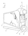
- a forklift is shown as an industrial truck according to the invention.
- a vehicle frame 1 on which a driver's cab 2 is arranged can be seen.
- the rear of the truck is formed by a counterweight 4.
- the various units of the travel drive arrangement for the industrial truck are arranged in the area of the frame 1 of the industrial truck and are in the figure shown schematically.
- the travel drive arrangement includes one Internal combustion engine 5, which is connected to an electrical generator 6.
- the in generator 6 designed as a three-phase generator in this exemplary embodiment transmits the generated electrical energy via an electrical, not shown Line to a converter 7, the rectifier, an electronic Control unit and an inverter comprises.
- the converter 7 is with a Housing of a drive axle 8 connected, in which a travel drive motor 9, preferably an asynchronous motor, the truck is arranged.
- motor 9 have a common cooling device with a liquid cooling medium.
- Coolant lines 10 lead from a heat exchanger 11 of the cooling device to the internal combustion engine 5, to the generator 6 and to Drive axis 8.
- the cooling medium is used to remove the The heat dissipated by the units is released into the environment.
- the arrangement of the Converter on the drive axis 8 reduces the number of required Coolant lines, since the electric motor 9 is also in the area of the drive axle 8 is arranged.
- FIGS. 2 and 3 show two electric three-phase machines known per se, which are suitable for use in an industrial truck according to the invention. Three-phase machines are used here as electric motors and as generators used.
- FIG. 2 shows a three-phase asynchronous motor in which a non-rotatable Housing 21 a stator winding 22 is attached.
- a rotor designed as a squirrel-cage rotor 23 is connected in a torsionally rigid manner to a shaft 24 which is opposite the housing 21 rotatably mounted.
- the housing In the area of the stator winding 22, the housing extends over the circumference of the Housing 21 extending coolant channel 25. Especially those in the area of Stator winding 22 is generated with the coolant channel 25th flowing cooling medium discharged from the electrical machine.
- FIG 3 is a corresponding arrangement for a three-phase synchronous generator shown.
- a rotor 33 of the generator is provided with a flange 34, for example a crankshaft of an internal combustion engine connectable.
- the rotor 33 includes a Laminated core 33a with permanent magnets attached. Even with this machine on a housing 31 in the area of a stator winding 32 a rotating one Coolant channel 35 is arranged, through which a cooling medium flows. In front All of the thermal energy generated in the stator winding 32 is used in the latter Arrangement taken up by the cooling medium.
Landscapes
- Engineering & Computer Science (AREA)
- Transportation (AREA)
- Mechanical Engineering (AREA)
- Chemical & Material Sciences (AREA)
- Structural Engineering (AREA)
- Combustion & Propulsion (AREA)
- Life Sciences & Earth Sciences (AREA)
- Civil Engineering (AREA)
- Geology (AREA)
- Power Engineering (AREA)
- Sustainable Energy (AREA)
- Sustainable Development (AREA)
- Electric Propulsion And Braking For Vehicles (AREA)
- Motor Or Generator Cooling System (AREA)
- Hybrid Electric Vehicles (AREA)
- Cooling, Air Intake And Gas Exhaust, And Fuel Tank Arrangements In Propulsion Units (AREA)
- Arrangement Or Mounting Of Propulsion Units For Vehicles (AREA)
Description
- Figur 1
- eine erfindungsgemäßes Flurförderzeug,
- Fig. 2 und Fig. 3
- erfindungsgemäße elektrische Maschinen.
Claims (10)
- Flurförderzeug mit einem im Frontbereich angeordneten Hubgerüst (3), einem im Heckbereich angeordneten Gegengewicht (4), einer mindestens ein elektrisches Aggregat aufweisenden Fahrantriebsanordnung und einer Kühlvorrichtung für das elektrische Aggregat, wobei als elektrisches Aggregat mindestens ein elektrischer Motor (9) und mindestens ein Umrichter vorgesehen ist und ein Rotor (23, 33) des elektrischen Motors (9) mechanisch an ein Fahrantriebsrad des Flurförderzeugs gekoppelt ist, dadurch gekennzeichnet, daß der elektrische Motor (9) in einer Antriebsachse (8) des Flurförderzeugs angeordnet ist, ein Gehäuse des Umrichters (7) mit der Antriebsachse (8) verbunden ist und die Kühlvorrichtung für die elektrischen Aggregate ein flüssiges Kühlmedium aufweist.
- Flurförderzeug nach Anspruch 1, dadurch gekennzeichnet, daß als weiteres elektrisches Aggregat mindestens ein elektrischer Generator (6) vorgesehen ist.
- Flurförderzeug nach Anspruch 2 dadurch gekennzeichnet, daß an einem Gehäuse des elektrischen Generators (6) und/oder an einem Gehäuse des elektrischen Motors (9) mindestens ein Kanal für das flüssige Kühlmedium angeordnet ist.
- Flurförderzeug nach einem der Ansprüche 2 bis 3, dadurch gekennzeichnet, daß der elektrische Generator (6) und/oder der elektrische Motor (9) als Drehstromgenerator bzw. als Drehstrommotor ausgeführt sind.
- Flurförderzeug nach einem der Ansprüche 2 bis 4, dadurch gekennzeichnet, daß ein Rotor (23, 33) des elektrischen Generators (6) mechanisch an eine Kurbelwelle eines Verbrennungsmotors gekoppelt ist.
- Flurförderzeug nach einem der Ansprüche 1 bis 5, dadurch gekennzeichnet, daß das Kühlmedium der Kühlvorrichtung für das elektrische Aggregat von einer Kühlflüssigkeit eines Verbrennungsmotors (5) gebildet wird.
- Flurförderzeug nach einem der Ansprüche 1 bis 5, dadurch gekennzeichnet, daß das Kühlmedium der Kühlvorrichtung für das elektrische Aggregat von einem Arbeitsmedium einer Hydraulikanlage gebildet wird.
- Flurförderzeug nach einem der Ansprüche 1 bis 7, dadurch gekennzeichnet, daß ein von dem Kühlmedium der Kühlvorrichtung für das elektrische Aggregat durchströmter Wärmetauscher (11) vorgesehen ist.
- Flurförderzeug nach einem der Ansprüche 2 bis 8, dadurch gekennzeichnet, daß ein Gehäuse mindestens eines Umrichters (7) und ein Gehäuse des elektrischen Generators (6) miteinander verbunden sind.
- Flurförderzeug nach einem der Ansprüche 1 bis 9, dadurch gekennzeichnet, daß ein Gehäuse mindestens eines Umrichters (7) und ein Gehäuse mindestens eines elektrischen Motors (9) miteinander verbunden sind.
Applications Claiming Priority (2)
| Application Number | Priority Date | Filing Date | Title |
|---|---|---|---|
| DE19721526A DE19721526A1 (de) | 1997-05-22 | 1997-05-22 | Flurförderzeug mit einem elektrischen Aggregat |
| DE19721526 | 1997-05-22 |
Publications (3)
| Publication Number | Publication Date |
|---|---|
| EP0879724A2 EP0879724A2 (de) | 1998-11-25 |
| EP0879724A3 EP0879724A3 (de) | 2000-03-29 |
| EP0879724B1 true EP0879724B1 (de) | 2003-10-22 |
Family
ID=7830237
Family Applications (1)
| Application Number | Title | Priority Date | Filing Date |
|---|---|---|---|
| EP98109039A Expired - Lifetime EP0879724B1 (de) | 1997-05-22 | 1998-05-18 | Flurförderzeug mit einem elektrischen Aggregrat |
Country Status (4)
| Country | Link |
|---|---|
| EP (1) | EP0879724B1 (de) |
| JP (1) | JPH1146405A (de) |
| KR (1) | KR19980087204A (de) |
| DE (2) | DE19721526A1 (de) |
Families Citing this family (12)
| Publication number | Priority date | Publication date | Assignee | Title |
|---|---|---|---|---|
| DE19910046B4 (de) * | 1999-03-08 | 2012-09-06 | Still Gmbh | Fahrzeug mit einem Verbrennungsmotor und einem elektrischen Aggregat |
| AT408160B (de) * | 1999-03-17 | 2001-09-25 | Vaillant Gmbh | Kühleinrichtung eines brennstoffzellenstapels und dessen wechselrichter |
| DE10241420A1 (de) * | 2002-09-06 | 2004-03-18 | Still Gmbh | Flurförderzeug mit einem elektrischen Antrieb |
| DE10330690A1 (de) * | 2003-07-08 | 2005-02-24 | Zf Friedrichshafen Ag | Elektroachse mit Radnabenantrieb |
| JPWO2005071824A1 (ja) | 2004-01-26 | 2007-08-23 | 株式会社日立製作所 | 半導体装置 |
| DE102004059701B4 (de) * | 2004-12-10 | 2010-05-06 | Still Gmbh | Flurförderzeug mit einer luftdurchströmten Kühlvorrichtung |
| DE102008025142A1 (de) * | 2008-04-16 | 2009-10-22 | Still Gmbh | Flurförderzeug, insbesondere Gabelstapler, mit einem Hybridantrieb |
| ITTO20100310A1 (it) | 2010-04-16 | 2011-10-17 | Movimatica Srl | Veicolo sollevatore ibrido elettro-idraulico |
| CN105071617B (zh) * | 2015-09-08 | 2018-06-05 | 浙江双菱新能源科技有限公司 | 一体式永磁同步电机壳体 |
| DE102015225862A1 (de) * | 2015-12-18 | 2017-06-22 | Schaeffler Technologies AG & Co. KG | Pumpenaktor zur Kupplungs- und Gangstelleraktuierung in einem Getriebe eines Kraftfahrzeugs |
| US11427450B2 (en) | 2018-06-01 | 2022-08-30 | Hyster-Yale Group, Inc. | Lift truck having advantageous design elements |
| DE102018131384A1 (de) * | 2018-12-07 | 2020-06-10 | Still Gmbh | Elektrisch betriebenes Flurförderzeug |
Family Cites Families (5)
| Publication number | Priority date | Publication date | Assignee | Title |
|---|---|---|---|---|
| DE3941474A1 (de) * | 1989-12-15 | 1991-06-20 | Bosch Gmbh Robert | Fluessigkeitsgekuehlter elektrischer generator |
| JP3208772B2 (ja) * | 1990-05-24 | 2001-09-17 | セイコーエプソン株式会社 | 電気自動車 |
| ATA105093A (de) * | 1993-05-28 | 2001-07-15 | Steyr Daimler Puch Ag | Flüssigkeitsgekühlte antriebseinheit für ein elektromobil |
| JP3094772B2 (ja) * | 1994-02-21 | 2000-10-03 | トヨタ自動車株式会社 | 発電機を搭載する電気自動車の発電機出力制御装置 |
| DE4442867C2 (de) * | 1994-12-02 | 1999-09-09 | Mannesmann Sachs Ag | Antriebsanordnung für ein Fahrzeug, insbesondere ein Straßenfahrzeug |
-
1997
- 1997-05-22 DE DE19721526A patent/DE19721526A1/de not_active Ceased
-
1998
- 1998-05-18 DE DE59809946T patent/DE59809946D1/de not_active Expired - Fee Related
- 1998-05-18 EP EP98109039A patent/EP0879724B1/de not_active Expired - Lifetime
- 1998-05-20 KR KR1019980018087A patent/KR19980087204A/ko not_active Withdrawn
- 1998-05-22 JP JP10140682A patent/JPH1146405A/ja active Pending
Also Published As
| Publication number | Publication date |
|---|---|
| EP0879724A2 (de) | 1998-11-25 |
| EP0879724A3 (de) | 2000-03-29 |
| DE59809946D1 (de) | 2003-11-27 |
| KR19980087204A (ko) | 1998-12-05 |
| JPH1146405A (ja) | 1999-02-16 |
| DE19721526A1 (de) | 1998-11-26 |
Similar Documents
| Publication | Publication Date | Title |
|---|---|---|
| EP4234845B1 (de) | Autobetonpumpe | |
| EP0642944B1 (de) | Kühlvorrichtung für ein Batterieladegerät und einen Bordnetzwandler in Elektrofahrzeugen | |
| DE102013204766A1 (de) | Elektrische Fahrzeugachsenvorrichtung | |
| DE112007002745T5 (de) | Kühlstruktur für einen Wechselrichter und einen Kondensator, die einstückig mit dem Motor im Motorgehäuse untergebracht sind, Motoreinheit mit Kühlstruktur und Gehäuse | |
| EP3713805A1 (de) | Drehgestell eines schienenfahrzeugs | |
| DE102015214053A1 (de) | Elektroantriebseinheit, insbesondere für ein Elektrofahrzeug | |
| EP1717090B1 (de) | Allradangetriebenes Kraftfahrzeug | |
| EP0879724A2 (de) | Flurförderzeug mit einem elektrischen Aggregrat | |
| DE102011078192A1 (de) | Generatoreinheit für ein landwirtschaftliches oder kommunales Nutzfahrzeug | |
| DE102013208976A1 (de) | Vollintegrierte elektrische Antriebsvorrichtung | |
| DE102021126017B4 (de) | Hybrid-elektrofahrzeug | |
| EP2990249A2 (de) | Hybridantriebsanordnung für ein fahrzeug | |
| DE4137535C2 (de) | Maschinensatz zur Energieversorgung | |
| EP0716966A2 (de) | Antriebseinheit | |
| EP2849318B1 (de) | Elektrische Antriebseinheit für Fahrzeuge | |
| DE102012007623B4 (de) | Motor-Getriebe-Einheit | |
| DE102005037726A1 (de) | Antriebsachse mit einem Elektro-Wandler | |
| DE102008029141A1 (de) | Flurförderzeug | |
| DE2732974A1 (de) | Antriebsbaugruppe fuer nutzfahrzeuge | |
| EP1968170B1 (de) | Antriebseinheit insbesondere für Flurförderzeug | |
| DE102019208001A1 (de) | Elektromotor und Schienenfahrzeug | |
| DE102018218820A1 (de) | Elektrische Maschine mit einer Fluid-Kühleinrichtung | |
| DE102005037727A1 (de) | Fahrantrieb mit einem Elektro-Wandler | |
| EP2110358B1 (de) | Flurförderzeug, insbesondere Gabelstapler, mit einem Hybridantrieb | |
| EP0928513B1 (de) | Fahrzeug mit elektrischem antriebsmotor |
Legal Events
| Date | Code | Title | Description |
|---|---|---|---|
| PUAI | Public reference made under article 153(3) epc to a published international application that has entered the european phase |
Free format text: ORIGINAL CODE: 0009012 |
|
| AK | Designated contracting states |
Kind code of ref document: A2 Designated state(s): DE FR GB IT |
|
| AX | Request for extension of the european patent |
Free format text: AL;LT;LV;MK;RO;SI |
|
| PUAL | Search report despatched |
Free format text: ORIGINAL CODE: 0009013 |
|
| AK | Designated contracting states |
Kind code of ref document: A3 Designated state(s): AT BE CH CY DE DK ES FI FR GB GR IE IT LI LU MC NL PT SE |
|
| AX | Request for extension of the european patent |
Free format text: AL;LT;LV;MK;RO;SI |
|
| 17P | Request for examination filed |
Effective date: 20000610 |
|
| AKX | Designation fees paid |
Free format text: DE FR GB IT |
|
| 17Q | First examination report despatched |
Effective date: 20020430 |
|
| GRAH | Despatch of communication of intention to grant a patent |
Free format text: ORIGINAL CODE: EPIDOS IGRA |
|
| GRAS | Grant fee paid |
Free format text: ORIGINAL CODE: EPIDOSNIGR3 |
|
| GRAA | (expected) grant |
Free format text: ORIGINAL CODE: 0009210 |
|
| AK | Designated contracting states |
Kind code of ref document: B1 Designated state(s): DE FR GB IT |
|
| REG | Reference to a national code |
Ref country code: GB Ref legal event code: FG4D Free format text: NOT ENGLISH |
|
| REF | Corresponds to: |
Ref document number: 59809946 Country of ref document: DE Date of ref document: 20031127 Kind code of ref document: P |
|
| GBT | Gb: translation of ep patent filed (gb section 77(6)(a)/1977) |
Effective date: 20031212 |
|
| ET | Fr: translation filed | ||
| PLBE | No opposition filed within time limit |
Free format text: ORIGINAL CODE: 0009261 |
|
| STAA | Information on the status of an ep patent application or granted ep patent |
Free format text: STATUS: NO OPPOSITION FILED WITHIN TIME LIMIT |
|
| 26N | No opposition filed |
Effective date: 20040723 |
|
| PGFP | Annual fee paid to national office [announced via postgrant information from national office to epo] |
Ref country code: FR Payment date: 20050511 Year of fee payment: 8 |
|
| PGFP | Annual fee paid to national office [announced via postgrant information from national office to epo] |
Ref country code: DE Payment date: 20050512 Year of fee payment: 8 |
|
| PGFP | Annual fee paid to national office [announced via postgrant information from national office to epo] |
Ref country code: GB Payment date: 20050518 Year of fee payment: 8 |
|
| PG25 | Lapsed in a contracting state [announced via postgrant information from national office to epo] |
Ref country code: GB Free format text: LAPSE BECAUSE OF NON-PAYMENT OF DUE FEES Effective date: 20060518 |
|
| PGFP | Annual fee paid to national office [announced via postgrant information from national office to epo] |
Ref country code: IT Payment date: 20060531 Year of fee payment: 9 |
|
| PG25 | Lapsed in a contracting state [announced via postgrant information from national office to epo] |
Ref country code: DE Free format text: LAPSE BECAUSE OF NON-PAYMENT OF DUE FEES Effective date: 20061201 |
|
| GBPC | Gb: european patent ceased through non-payment of renewal fee |
Effective date: 20060518 |
|
| REG | Reference to a national code |
Ref country code: FR Ref legal event code: ST Effective date: 20070131 |
|
| PG25 | Lapsed in a contracting state [announced via postgrant information from national office to epo] |
Ref country code: FR Free format text: LAPSE BECAUSE OF NON-PAYMENT OF DUE FEES Effective date: 20060531 |
|
| PG25 | Lapsed in a contracting state [announced via postgrant information from national office to epo] |
Ref country code: IT Free format text: LAPSE BECAUSE OF NON-PAYMENT OF DUE FEES Effective date: 20070518 |