EP0879403B1 - Verfahren zur herstellung einer schutzkappe für ein in eine körperhöhle einbringbares infrarot-strahlungsthermometer - Google Patents
Verfahren zur herstellung einer schutzkappe für ein in eine körperhöhle einbringbares infrarot-strahlungsthermometer Download PDFInfo
- Publication number
- EP0879403B1 EP0879403B1 EP97902326A EP97902326A EP0879403B1 EP 0879403 B1 EP0879403 B1 EP 0879403B1 EP 97902326 A EP97902326 A EP 97902326A EP 97902326 A EP97902326 A EP 97902326A EP 0879403 B1 EP0879403 B1 EP 0879403B1
- Authority
- EP
- European Patent Office
- Prior art keywords
- base body
- protective cap
- film
- window film
- body material
- Prior art date
- Legal status (The legal status is an assumption and is not a legal conclusion. Google has not performed a legal analysis and makes no representation as to the accuracy of the status listed.)
- Expired - Lifetime
Links
Images
Classifications
-
- G—PHYSICS
- G01—MEASURING; TESTING
- G01J—MEASUREMENT OF INTENSITY, VELOCITY, SPECTRAL CONTENT, POLARISATION, PHASE OR PULSE CHARACTERISTICS OF INFRARED, VISIBLE OR ULTRAVIOLET LIGHT; COLORIMETRY; RADIATION PYROMETRY
- G01J5/00—Radiation pyrometry, e.g. infrared or optical thermometry
- G01J5/02—Constructional details
- G01J5/05—Means for preventing contamination of the components of the optical system; Means for preventing obstruction of the radiation path
-
- G—PHYSICS
- G01—MEASURING; TESTING
- G01J—MEASUREMENT OF INTENSITY, VELOCITY, SPECTRAL CONTENT, POLARISATION, PHASE OR PULSE CHARACTERISTICS OF INFRARED, VISIBLE OR ULTRAVIOLET LIGHT; COLORIMETRY; RADIATION PYROMETRY
- G01J5/00—Radiation pyrometry, e.g. infrared or optical thermometry
- G01J5/02—Constructional details
- G01J5/021—Probe covers for thermometers, e.g. tympanic thermometers; Containers for probe covers; Disposable probes
-
- Y—GENERAL TAGGING OF NEW TECHNOLOGICAL DEVELOPMENTS; GENERAL TAGGING OF CROSS-SECTIONAL TECHNOLOGIES SPANNING OVER SEVERAL SECTIONS OF THE IPC; TECHNICAL SUBJECTS COVERED BY FORMER USPC CROSS-REFERENCE ART COLLECTIONS [XRACs] AND DIGESTS
- Y10—TECHNICAL SUBJECTS COVERED BY FORMER USPC
- Y10T—TECHNICAL SUBJECTS COVERED BY FORMER US CLASSIFICATION
- Y10T156/00—Adhesive bonding and miscellaneous chemical manufacture
- Y10T156/10—Methods of surface bonding and/or assembly therefor
- Y10T156/1052—Methods of surface bonding and/or assembly therefor with cutting, punching, tearing or severing
- Y10T156/1062—Prior to assembly
Definitions
- the present invention relates to methods for producing an on an ear canal temperature measuring probe of a cup-shaped infrared radiation thermometer Protective cap, which can be inserted into a body cavity, and a tubular base body made of plastic, one end open and the opposite End with a window film that is transparent to infrared radiation.
- Body temperature is measured using electronic radiation thermometers, among other things measured.
- a radiation thermometer typically has a housing a radiation entrance window, internal optics and an infrared sensor that is assigned to an evaluation unit.
- the radiation entrance window serves to Complete the interior of the housing of the radiation thermometer and so the optics and protect the sensor from contamination and destruction.
- To determine the A person's body temperature becomes the front end of the thermometer in the ear directed.
- the infrared radiation emitted by the eardrum and the ear canal enters the thermometer over the window and falls over the optics or a light guide and an interference filter on the infrared sensor.
- the temperature increase caused in the sensor results in an electrical output voltage, from which, via an evaluation unit, the radiation temperature can be determined.
- protective caps of the type mentioned at the end of the Thermometer placed, for example, via the ear canal probe of an infrared radiation sensitive Middle ear thermometer pushed; such protective caps are described for example in EP-B-0201790.
- These protective caps are not used only to protect the window that allows infrared radiation, but should Also protect users from disease transmission by taking a temperature measurement or one before measuring the temperature for changing people new protective cap is put on.
- the protective cap described in EP-B-0201790 has an infrared-transmissive membrane made of polypropylene or polyethylene consists. The part that supports the membrane is an injection molded part.
- protective caps are generally disposable, they are made according to them Use removed and discarded to create a new one for the next temperature measurement To put a protective cap on the thermometer, it should be with such protective caps to be an inexpensive item.
- the main cost at Production of such protective caps is not caused by the material costs, but through the manufacturing process.
- Such protective caps are usually used manufactured in that a base body made of plastic is injection-molded tubular and then the one, open end of this body with a window film that for infrared radiation is transparent, is closed. To such a manufacture Protective cap by means of injection molding is pointed out in US Pat. No. 5,293,862.
- Flat protective caps are known from EP-A-0589212 and EP-A-0637430, which consist of two or three foils lying flat on top of each other. In the middle of the first There is a hole in the film. The second film is transparent to infrared and with the first Foil welded at the corners. Only when a user has such a flat protective cap on the ear canal probe of a radiation thermometer by using the End of the ear canal probe through the hole in the second infrared transparent film presses the first film, the flat protective cap receives one of the outer shape of the ear canal probe corresponding cup-shaped shape. After the measurement, the protective cap removed again from the ear canal probe, its cup-shaped shape is lost again.
- the base body is made from a sheet, sheet or plate-shaped base material made and with a Provided window film.
- a sheet, sheet or plate-shaped base material made and with a Provided window film.
- Such materials can be used continuously on a production line fed and then subjected to punching, shaping and cutting operations become.
- This two-layer structure enables window formation with simultaneous Apply thermal insulation to the outer layer.
- many protective caps can be continuously produced from the conveyor in the shortest possible time. Cooling times, as are known in the injection molding of such parts, are omitted here.
- the base material can also be made entirely of a foam sheet or one other plastic film provided with air pockets, then through the window area for better transmission of infrared radiation Hot stamping or pressing is diluted.
- sheet-like material with a certain flexibility is used, so can this web material be unwound from a supply roll (claim 5), preferably in the form of an endless tape stored on the supply roll (claim 7). But there is also the possibility of using the material, at least that for the basic body to be removed from a stack and the subsequent processing stations feed continuously.
- the base body material in a first step first provide holes in which these are punched out (claim 2). These holes are each towards the open end of the forming base body from which the protective cap is made.
- such protective caps have a film-like window that is as thin as possible and for the radiation in the relevant measuring range should be permeable.
- a window film which preferably has a thickness in the range of Has 20 to 50 microns (claim 9), and the perforated base material and Window film are by welding (claim 3) and / or by gluing (claim 4) connected to each other.
- the film is not is different in thickness from protective cap to protective cap; because such differences in thickness can the measurement result with a radiation thermometer, in which a such a protective cap with a window film is influenced.
- a radiation thermometer in which a such a protective cap with a window film is influenced.
- the holes are not only in a row in the base material can be formed, but are preferably formed in a field arrangement, at several rows of holes are punched across the production direction.
- base material is preferably a film with a thickness in the range of 0.4 to 0.8 mm (Claim 8) supplied.
- the base body material preferably consists of a plastic, in particular polyethylene or polystyrene (claim 11).
- the pre-prepared material of a third processing station supplied where the protective cap is formed by deep drawing (claim 13), where, according to the field division of the punched holes, an entire field deep-drawn shapes can be generated and each deep-drawn shape Window is assigned.
- the still connected, deep-drawn Field of basic bodies is subjected to a fourth processing step, where the individual Protective caps can be machined to final dimensions, for example by punching them out become.
- This one Protective cap reduces the heat input, cooling at the same time, for example, the ear canal. This also means that the Reduced ear cooling from the user to the thermometer with this protective cap is perceived as warmer and therefore much more pleasant. Furthermore, this can heat-insulating agents are designed to be soft and is more pleasant in the ear than one solid, unyielding material or a protective cap covered with it.
- Another Such a protective cap is particularly advantageous when it is connected is used with a clinical thermometer with a small temperature probe. A clinical thermometer with a small temperature probe is suitable for both Temperature measurement in adults as well as children by using this protective cap is made of heat insulating material in at least two sizes. A such a protective cap can also be made of a particularly soft, heat-insulating and thus flexible material that can be used both in adults and also in children at their respective ear canal, despite the different size, adjusts.
- Heat-insulating material as a foam offers the advantage that the heat-insulating Properties, especially due to the type of foam in relation to pore size and thus share of the air and in relation to open-pore or closed-pore Foam (closed-pore foam is preferred) can be. It is also possible to emboss and foam materials deform irreversibly, especially when heat is applied, so that in particular Edge areas of this base body are thinned (for example in the area of the hole) that the film is applied) or can be thickened like a bead (e.g. at the bottom, edge of the disposable cap opposite the window opening). (See claims 16, 19 and 20).
- the dilution of the starting material in the area of the window is preferably in several individual, hot or cold shaping deformation steps (claim 22) performed.
- Thinner material in the area of the window film leads to the fact that Thickness of the film prevents possible own emissions, which otherwise the radiation components incident on the sensors of a radiation thermometer, the attributable to heat radiation emitted by the body, could falsify.
- the dilution of the one is preferred Area of the starting material, which is assigned to the window film, to the final dimension made in the deep-drawing step (claim 23), so that ensured can be that the required thicknesses of the film are observed, which otherwise through this final deep-drawing step, if the film has already reached its final dimensions was shaped, could be influenced.
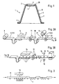
- a front end of an infrared thermometer (not shown) is that can be used as a clinical thermometer, for example Protective cap 1 placed, in addition to their property as protection against contamination thermal radiation of the entrance window of the radiation thermometer forms.
- the protective cap 1 is on the radiation thermometer (not shown) and then with the front one End 2, for example, inserted into an ear canal (not shown) to the emitted Measure infrared radiation.
- the protective cap has a tubular base body 3, which at the lower end 4 is open. At the upper or front end 2 there is a hole or an opening 5 provided which forms a radiation entrance window and which advantageously by is surrounded by a stiffening ring 20.
- the protective cap 1 constructed in two layers, namely from a base body material 6 and a film material 7. While the base body material 6 has the relatively dimensionally stable base body 3 1 is the film material 7 over the entire inner surface of the base body 3 pulled and spanned the hole 5, thus forming the Radiation entry window.
- suitable tape 22 becomes base material 6 withdrawn from a supply roll 8 and fed to a punching device 9.
- base material is preferably a polyethylene or polystyrene film with a thickness in the range of 0.4 to 0.8 mm.
- punch 9 are in the band-shaped base material holes 5 are continuously punched, whereby it is these holes 5 are those in the finished protective cap 1 the hole 5 each form that represents the radiation entrance window.
- the film material 7 is pressed against the base body material via pressure rollers 13 and welded or glued to it under the action of heat.
- This composite in the form of the base body and the film material 6, 7 is then fed to a deep-drawing station 24, which is shown schematically in FIG. 2B, at which a protective cap is deep-drawn in the region of each hole 5, with a shape such as that shown in FIG corresponds to Fig. 1.
- This process step 3 following the deep-drawing, the band 22 in a fourth Undergo quality control at a fourth processing station.
- an infrared radiation source 15 is provided in the fourth processing station 14, their radiation on the wavelength range relevant for the temperature measurement each opening 5, which is closed with the film material 7, is directed.
- a sensor 16 is arranged below of the band 22, which detects the transmitted radiation components detected. If the transmission properties of the window film 7 do not meet the quality requirements correspond, such a protective cap 1 is marked and in the finishing station 17, where the protective cap 1 is separated from the tape and on Finished dimensions are processed, not treated.
- FIG. 3 a process sequence for the continuous production of protective caps is shown, in which only a single sheet material is required according to the second invention is.
- a base body material 18 is supplied which is well embossed and / or deforms. This is especially polyethylene, which is On the one hand, it is suitable for forming a relatively stable base body, and that on the other hand, it is also suitable in that relevant for a body temperature measurement Area to transmit infrared radiation.
- This main body material 18 is then immediately fed to an embossing station 19, preferably in several successive advanced, the material is deformed so that the output side the embossing station 18 individual protective caps 1 are formed from the base body material are, the front end 2 of the protective cap 1, in which the window 7 is formed is pointing down.
- the protective cap 1 can be formed Wall areas of different thicknesses in accordance with the requirements of protective cap 1 are formed, in the region of the window 7, the starting material 18 to a very thin film, i.e. the window film 7 is deformed.
- the starting material 18 only formative, also in several steps, can be profiled.
- the actual pipe or Cup-shaped shape of the protective cap according to FIG. 1 is then in one downstream deep-drawing step, as it is explained with reference to FIG. 2B, deformed.
- a quality control is then carried out in accordance with FIG. 2B and machining to the final dimensions of the individual protective caps.
Landscapes
- Physics & Mathematics (AREA)
- General Physics & Mathematics (AREA)
- Spectroscopy & Molecular Physics (AREA)
- Radiation Pyrometers (AREA)
- Measuring And Recording Apparatus For Diagnosis (AREA)
- Photometry And Measurement Of Optical Pulse Characteristics (AREA)
Description
- Fig. 1
- einen schematischen Querschnitt einer Schutzkappe mit Fensterfolie,
- Fig. 2A und Fig. 2B
- schematisch einen Verfahrensablauf zur Herstellung einer Schutzkappe ähnlich derjenigen, die in Fig. 1 dargestellt ist, und
- Fig. 3
- schematisch einen Teil einer Fertigungslinie zum Herstellen von Schutzkappen unter Prägen eines Ausgangsmaterials.
Claims (23)
- Verfahren zur Herstellung einer auf eine Ohrkanal-Temperaturmeßsonde eines Infrarot-Strahlungsthermometers aufsetzbaren becherförmigen Schutzkappe (1), die einen rohrförmigen Grundkörper (3) aus Kunststoff aufweist, dessen eines Ende offen und dessen gegenüberliegendes Ende mit einer für infrarote Strahlung durchlässigen Fenster-Folie (7) abgeschlossen ist, mit den folgenden Schritten:Einbringen eines Lochs (5) in ein zur Bildung des Grundkörpers (3) vorgesehenes blatt-, folien-, bahnen- oder plattenförmiges Grundkörper-Material (6),Bedecken und unverrückbares Verbinden des gelochten Grundkörper-Materials (6) wenigstens im Bereich des Lochs (5) mit einer Fenster-Folie (7) aus für infrarote Strahlung durchlässigem Kunststoff,Verformen des Verbundkörpers zu einer Schutzkappe (1), undgegebenenfalls Bearbeitung der Schutzkappe (1) auf Endabmessungen.
- Verfahren nach Anspruch 1,
dadurch gekennzeichnet,
daß das Loch (5) in das Grundkörper-Material (6) gestanzt wird. - Verfahren nach Anspruch 1,
dadurch gekennzeichnet,
daß das gelochte Grundkörper-Material (6) und die Fenster-Folie (7) durch Schweißen unverrückbar miteinander verbunden werden. - Verfahren nach Anspruch 1,
dadurch gekennzeichnet,
daß das gelochte Grundkörper-Material (6) und die Fenster-Folie (7) durch Kleben unverrückbar miteinander verbunden werden. - Verfahren nach Anspruch 1,
dadurch gekennzeichnet,
daß das Grundkörper-Material (6) von einer ersten Vorratsrolle (8) abgewickelt und danach in einem ersten Schritt gelocht wird. - Verfahren nach Anspruch 1 oder 5,
dadurch gekennzeichnet,
daß die Fenster-Folie (7) von einer zweiten Vorratsrolle (12) abgewickelt und in einem zweiten Schritt mit dem gelochten Grundkörper-Material (6) verbunden wird. - Verfahren nach Anspruch 5,
dadurch gekennzeichnet,
daß das Grundkörper-Material (6) als Band zugeführt wird, wobei in dem ersten Schritt eine Folge von Löchern (5) eingebracht wird, und nach der Verformung die hergestellten Schutzkappen in einem weiteren Schritt von dem Band abgetrennt werden. - Verfahren nach Anspruch 1,
dadurch gekennzeichnet,
daß als Grundkörper-Material (6) eine Folie (7) mit einer Dicke im Bereich von 0,4 bis 0,8 mm verwendet wird. - Verfahren nach Anspruch 1,
dadurch gekennzeichnet,
daß eine Fenster-Folie (7) mit einer Dicke im Bereich von 20 bis 50 µm verwendet wird. - Verfahren nach Anspruch 1 oder 6,
dadurch gekennzeichnet,
daß die Fenster-Folie (7) auf die Oberseite (21) des Grundkörper-Materials (6) aufgebracht wird und nach der Verformung einen Innenüberzug der Schutzkappe bildet. - Verfahren nach Anspruch 1,
dadurch gekennzeichnet,
daß als Grundkörper-Material (6) eine Folie aus Kunststoff, insbesondere Polyethylen oder Polystyrol, verwendet wird. - Verfahren nach Anspruch 1
dadurch gekennzeichnet,
daß als Fenster-Folie (7) eine solche aus der Gruppe der Polyethylene oder Polypropylene verwendet wird. - Verfahren nach Anspruch 1,
dadurch gekennzeichnet,
daß in einem dritten Schritt durch Tiefziehen die Schutzkappe (1) geformt wird. - Verfahren nach Anspruch 1,
dadurch gekennzeichnet,
daß als Grundkörper-Material (6) ein wärmeisolierendes Material eingesetzt wird. - Verfahren nach Anspruch 14,
dadurch gekennzeichnet,
daß als wärmeisolierendes Material Schaumstoff eingesetzt wird. - Verfahren nach einem der Ansprüche 1, 14 oder 15,
dadurch gekennzeichnet,
daß der Verformungsschritt durch Prägen vorgenommen wird. - Verfahren nach Anspruch 1
dadurch gekennzeichnet,
daß vor der Bearbeitung auf Endabmessungen eine Qualitätsprüfung durchgeführt wird. - Verfahren nach Anspruch 17,
dadurch gekennzeichnet,
daß die Fenster-Folie (7) hinsichtlich ihrer Durchlässigkeit in dem für die Temperaturmessung relevanten Infrarot-Strahlungsbereich geprüft wird. - Verfahren nach Anspruch 1,
dadurch gekennzeichnet,
daß entlang des Randes des mit der Fenster-Folie abgeschlossenen Lochs eine
ringförmige Verstärkung (20) geformt wird. - Verfahren nach Anspruch 19,
dadurch gekennzeichnet,
daß die ringförmige Verstärkung (20) während des Verformungs-Schritts gebildet wird. - Verfahren zur Herstellung einer auf eine Ohrkanal-Temperaturmeßsonde eines Infrarot-Strahlungsthermometers aufsetzbaren becherförmigen Schutzkappe (1), die einen rohrförmigen Grundkörper (3) aus Kunststoff aufweist, dessen eines Ende offen und dessen gegenüberliegendes Ende mit einer für infrarote Strahlung durchlässigen Fenster-Folie (7) abgeschlossen ist, mit den folgenden Schritten:Verdünnen eines zur Bildung des Grundkörpers (3) vorgesehenen blatt-, folien-, bahnen- oder plattenförmigen Grundkörper-Materials (6) durch Prägen in einem vorgegebenen Bereich, der der zu bildenden Fenster-Folie (7) zugeordnet ist,Verformen des Grundkörper-Materials (6) durch Tiefziehen oder Prägen zu einer Schutzkappe (1),und gegebenenfalls Bearbeitung der Schutzkappe (1) auf Endabmessungen.
- Verfahren nach Anspruch 21,
dadurch gekennzeichnet,
daß der vorgegebene Bereich in mehreren Prägestufen verdünnt wird. - Verfahren nach Anspruch 22,
dadurch gekennzeichnet,
daß die Verdünnung des vorgegebenen Bereichs auf die Enddicke der Fenster-Folie (7) im Rahmen des Tiefziehens oder Prägens durchgeführt wird.
Applications Claiming Priority (3)
| Application Number | Priority Date | Filing Date | Title |
|---|---|---|---|
| DE19604200A DE19604200A1 (de) | 1996-02-06 | 1996-02-06 | Verfahren zur Herstellung einer Schutzkappe für ein in eine Körperhöhle einbringbares Infrarot-Strahlungsthermometer |
| DE19604200 | 1996-02-06 | ||
| PCT/EP1997/000505 WO1997029350A1 (de) | 1996-02-06 | 1997-02-05 | Verfahren zur herstellung einer schutzkappe für ein in eine körperhöhle einbringbares infrarot-strahlungsthermometer |
Publications (2)
| Publication Number | Publication Date |
|---|---|
| EP0879403A1 EP0879403A1 (de) | 1998-11-25 |
| EP0879403B1 true EP0879403B1 (de) | 2001-06-20 |
Family
ID=7784617
Family Applications (1)
| Application Number | Title | Priority Date | Filing Date |
|---|---|---|---|
| EP97902326A Expired - Lifetime EP0879403B1 (de) | 1996-02-06 | 1997-02-05 | Verfahren zur herstellung einer schutzkappe für ein in eine körperhöhle einbringbares infrarot-strahlungsthermometer |
Country Status (9)
| Country | Link |
|---|---|
| US (1) | US6156148A (de) |
| EP (1) | EP0879403B1 (de) |
| JP (1) | JP2000504826A (de) |
| CN (1) | CN1135370C (de) |
| AT (1) | ATE202416T1 (de) |
| DE (2) | DE19604200A1 (de) |
| DK (1) | DK0879403T3 (de) |
| ES (1) | ES2160320T3 (de) |
| WO (1) | WO1997029350A1 (de) |
Families Citing this family (21)
| Publication number | Priority date | Publication date | Assignee | Title |
|---|---|---|---|---|
| DE19604201A1 (de) * | 1996-02-06 | 1997-08-07 | Braun Ag | Schutzkappe |
| US6319206B1 (en) * | 1999-11-24 | 2001-11-20 | Exergen Corporation | Temporal thermometer disposable cap |
| DE10024681C2 (de) * | 2000-05-18 | 2003-07-10 | Oriental System Technology Inc | Verfahren zum Herstellen von Sondenabdeckungen und Sondenabdeckungen |
| US6371639B1 (en) * | 2000-10-13 | 2002-04-16 | Radiant Innovation Inc. | Probe cover of a tympanic thermometer and method for manufacturing the same |
| JP2002345761A (ja) * | 2001-05-22 | 2002-12-03 | Omron Corp | 赤外線体温計用プローブ |
| ITVA20020014A1 (it) * | 2002-02-19 | 2003-08-19 | Tecnimed Srl | Cappuccio igienico per termometri infarosso a contatto |
| ATE371173T1 (de) * | 2003-01-06 | 2007-09-15 | Covidien Ag | Sondenabdeckung für trommelfellthermometer |
| US7354194B2 (en) | 2003-01-06 | 2008-04-08 | Covidien Ag | Tympanic thermometer probe cover with film support mechanism |
| US7478946B2 (en) | 2003-01-06 | 2009-01-20 | Covidien Ag | Probe cover cassette with improved probe cover support |
| US7686506B2 (en) | 2003-01-06 | 2010-03-30 | Covidien Ag | Stackable tympanic thermometer probe cover cassette |
| US20070248141A1 (en) | 2006-04-21 | 2007-10-25 | Sherwood Services Ag | Infrared thermometer and probe cover thereof |
| TWI280356B (en) * | 2006-05-09 | 2007-05-01 | Radiant Innovation Inc | Ear cap of ear thermometer |
| US7556424B2 (en) * | 2006-05-19 | 2009-07-07 | Covidien Ag | Tympanic thermometer prove cover cassette and holder |
| US7722250B2 (en) * | 2006-10-11 | 2010-05-25 | Radiant Innovation Inc. | Probe cover for ear thermometer |
| TWM326151U (en) * | 2007-06-22 | 2008-01-21 | Actherm Inc | Disposable thermometer probe sheath |
| US8186876B2 (en) * | 2009-04-20 | 2012-05-29 | Welch Allyn, Inc. | Calibrated assembly for IR thermometer apparatus |
| US8136985B2 (en) * | 2009-05-05 | 2012-03-20 | Welch Allyn, Inc. | IR thermometer thermal isolation tip assembly |
| US20110228810A1 (en) * | 2010-02-09 | 2011-09-22 | O'hara Gary | Multiple object talking non-contact thermometer |
| US20110194585A1 (en) * | 2010-02-09 | 2011-08-11 | Abhishek Shrivastava | Multiple object non-contact thermometer |
| US9357930B2 (en) | 2012-03-19 | 2016-06-07 | Welch Allyn, Inc. | Temperature measurement system |
| AT512978B1 (de) * | 2012-06-08 | 2015-10-15 | Hagl Peter Dipl Ing | Abdeckkappe, Messgerät mit Abdeckkappe und Verfahren zur Herstellung einer Abdeckkappe |
Family Cites Families (7)
| Publication number | Priority date | Publication date | Assignee | Title |
|---|---|---|---|---|
| US4662360A (en) * | 1984-10-23 | 1987-05-05 | Intelligent Medical Systems, Inc. | Disposable speculum |
| US4911559A (en) * | 1988-11-01 | 1990-03-27 | Diatek, Inc. | Disposable probe cover assembly for medical thermometer |
| EP0419100A1 (de) * | 1989-09-19 | 1991-03-27 | Thermoscan Inc. | Abdeckung für eine Temperatursonde |
| US5088834A (en) * | 1990-08-24 | 1992-02-18 | Thermoscan Inc. | Unitary probe cover |
| ATE114808T1 (de) * | 1990-08-24 | 1994-12-15 | Thermoscan Inc | Einteilige sondenabdeckung. |
| EP0637430B1 (de) * | 1992-04-01 | 1999-12-08 | Omron Corporation | Schutzhülle für spekulum und herstellungsverfahren |
| JP2712024B2 (ja) * | 1992-09-19 | 1998-02-10 | 株式会社堀場製作所 | 鼓膜温度計用検鏡カバー |
-
1996
- 1996-02-06 DE DE19604200A patent/DE19604200A1/de not_active Ceased
-
1997
- 1997-02-05 US US09/117,723 patent/US6156148A/en not_active Expired - Fee Related
- 1997-02-05 EP EP97902326A patent/EP0879403B1/de not_active Expired - Lifetime
- 1997-02-05 AT AT97902326T patent/ATE202416T1/de not_active IP Right Cessation
- 1997-02-05 CN CNB971920273A patent/CN1135370C/zh not_active Expired - Fee Related
- 1997-02-05 JP JP9528134A patent/JP2000504826A/ja not_active Ceased
- 1997-02-05 DK DK97902326T patent/DK0879403T3/da active
- 1997-02-05 DE DE59703859T patent/DE59703859D1/de not_active Expired - Fee Related
- 1997-02-05 WO PCT/EP1997/000505 patent/WO1997029350A1/de not_active Ceased
- 1997-02-05 ES ES97902326T patent/ES2160320T3/es not_active Expired - Lifetime
Also Published As
| Publication number | Publication date |
|---|---|
| EP0879403A1 (de) | 1998-11-25 |
| WO1997029350A1 (de) | 1997-08-14 |
| CN1135370C (zh) | 2004-01-21 |
| DE19604200A1 (de) | 1997-08-07 |
| JP2000504826A (ja) | 2000-04-18 |
| ES2160320T3 (es) | 2001-11-01 |
| ATE202416T1 (de) | 2001-07-15 |
| US6156148A (en) | 2000-12-05 |
| DE59703859D1 (de) | 2001-07-26 |
| DK0879403T3 (da) | 2001-10-15 |
| CN1210589A (zh) | 1999-03-10 |
| HK1017071A1 (zh) | 1999-11-12 |
Similar Documents
| Publication | Publication Date | Title |
|---|---|---|
| EP0879403A1 (de) | Verfahren zur herstellung einer schutzkappe für ein in eine körperhöhle einbringbares infrarot-strahlungsthermometer | |
| EP0182139B1 (de) | Schale zur Aufnahme von Nahrungsmitteln, sowie Verfahren und Vorrichtung zu deren Herstellung | |
| US5674211A (en) | Method for manufacturing a material suitable for use as a top sheet of an absorbent disposable article, and one such material | |
| DE3521374A1 (de) | Verfahren zum herstellen eines folienverbundes und danach hergestellter folienverbund | |
| DE3026810C2 (de) | Vorrichtung zum Herstellen eines dünnwandigen tiefgezogenen Behälters | |
| EP0086869B1 (de) | Verfahren zum Verarbeiten von Schaumthermoplastfolie | |
| EP1287961A2 (de) | Verkleidungsteil sowie Verfahren und Vorrichtung zum Herstellen von mehrlagigen Verkleidungsteilen | |
| DE19652527A1 (de) | Absorber zum Absorbieren akustischer Schallwellen | |
| DE2647166A1 (de) | Laminiertes verpackungsmaterial und verfahren zu dessen herstellung | |
| DE102011010984B4 (de) | Verfahren zum partiellen Laminieren von flexiblen Substraten | |
| DE69131906T2 (de) | Verfahren zur herstellung von schicht-verbundwerkstoffen | |
| DE69707131T2 (de) | Verfahren und vorrichtung zum herstellen von blisterverpackungen | |
| DE69317180T2 (de) | Verfahren zur Herstellung von IC-Karten | |
| DE19635962C1 (de) | Verfahren zur Herstellung einer Einweg-Schutzkappe für ein Infrarot-Strahlungsthermometer | |
| EP1395427B1 (de) | Verfahren und vorrichtung zur herstellung eines tragbaren datenträgers | |
| WO2011134573A2 (de) | Verfahren zur herstellung von hohlkörpern aus thermoplastischem kunststoff | |
| DE2649526A1 (de) | Verfahren zum herstellen eines hauptsaechlich aus thermoplastischem material bestehendem mehrschichtigen behaelters und form zur ausfuehrung des verfahrens | |
| DE2625773B2 (de) | Verfahren zum Herstellen einer eine Oberflächenstruktur aufweisenden Verkleidung | |
| AT519010B1 (de) | Kfz-Bauteil | |
| WO1988008171A1 (fr) | Support pour piece d'identite et procede de fabrication de ce support | |
| WO2000069750A1 (de) | Folie, insbesondere für verpackungszwecke, sowie verpackung | |
| EP1043152B1 (de) | Verfahren und Vorrichtung zur Herstellung einer Folienbahn | |
| DE10024681C2 (de) | Verfahren zum Herstellen von Sondenabdeckungen und Sondenabdeckungen | |
| DE102019214316A1 (de) | Verfahren zur Herstellung eines Ventils, insbesondere eines Überdruckventils für einen Verpackungsbehälter | |
| DE19813387C2 (de) | Verfahren zur Herstellung eines rohrförmigen Hohlkörpers aus Polytetrafluorethylen oder aus einem PTFE-Recyclat |
Legal Events
| Date | Code | Title | Description |
|---|---|---|---|
| PUAI | Public reference made under article 153(3) epc to a published international application that has entered the european phase |
Free format text: ORIGINAL CODE: 0009012 |
|
| 17P | Request for examination filed |
Effective date: 19980629 |
|
| AK | Designated contracting states |
Kind code of ref document: A1 Designated state(s): AT BE CH DE DK ES FI FR GB GR IE IT LI LU MC NL PT SE |
|
| RAP1 | Party data changed (applicant data changed or rights of an application transferred) |
Owner name: BRAUN GMBH |
|
| GRAG | Despatch of communication of intention to grant |
Free format text: ORIGINAL CODE: EPIDOS AGRA |
|
| GRAG | Despatch of communication of intention to grant |
Free format text: ORIGINAL CODE: EPIDOS AGRA |
|
| GRAH | Despatch of communication of intention to grant a patent |
Free format text: ORIGINAL CODE: EPIDOS IGRA |
|
| 17Q | First examination report despatched |
Effective date: 20001201 |
|
| GRAH | Despatch of communication of intention to grant a patent |
Free format text: ORIGINAL CODE: EPIDOS IGRA |
|
| ITF | It: translation for a ep patent filed | ||
| GRAA | (expected) grant |
Free format text: ORIGINAL CODE: 0009210 |
|
| AK | Designated contracting states |
Kind code of ref document: B1 Designated state(s): AT BE CH DE DK ES FI FR GB GR IE IT LI LU MC NL PT SE |
|
| PG25 | Lapsed in a contracting state [announced via postgrant information from national office to epo] |
Ref country code: IE Free format text: LAPSE BECAUSE OF FAILURE TO SUBMIT A TRANSLATION OF THE DESCRIPTION OR TO PAY THE FEE WITHIN THE PRESCRIBED TIME-LIMIT Effective date: 20010620 Ref country code: FI Free format text: LAPSE BECAUSE OF FAILURE TO SUBMIT A TRANSLATION OF THE DESCRIPTION OR TO PAY THE FEE WITHIN THE PRESCRIBED TIME-LIMIT Effective date: 20010620 |
|
| REF | Corresponds to: |
Ref document number: 202416 Country of ref document: AT Date of ref document: 20010715 Kind code of ref document: T |
|
| REG | Reference to a national code |
Ref country code: CH Ref legal event code: EP |
|
| GBT | Gb: translation of ep patent filed (gb section 77(6)(a)/1977) |
Effective date: 20010621 |
|
| REG | Reference to a national code |
Ref country code: IE Ref legal event code: FG4D Free format text: GERMAN |
|
| REF | Corresponds to: |
Ref document number: 59703859 Country of ref document: DE Date of ref document: 20010726 |
|
| PG25 | Lapsed in a contracting state [announced via postgrant information from national office to epo] |
Ref country code: SE Free format text: LAPSE BECAUSE OF FAILURE TO SUBMIT A TRANSLATION OF THE DESCRIPTION OR TO PAY THE FEE WITHIN THE PRESCRIBED TIME-LIMIT Effective date: 20010920 Ref country code: PT Free format text: LAPSE BECAUSE OF FAILURE TO SUBMIT A TRANSLATION OF THE DESCRIPTION OR TO PAY THE FEE WITHIN THE PRESCRIBED TIME-LIMIT Effective date: 20010920 |
|
| PG25 | Lapsed in a contracting state [announced via postgrant information from national office to epo] |
Ref country code: GR Free format text: LAPSE BECAUSE OF FAILURE TO SUBMIT A TRANSLATION OF THE DESCRIPTION OR TO PAY THE FEE WITHIN THE PRESCRIBED TIME-LIMIT Effective date: 20010921 |
|
| REG | Reference to a national code |
Ref country code: DK Ref legal event code: T3 |
|
| REG | Reference to a national code |
Ref country code: ES Ref legal event code: FG2A Ref document number: 2160320 Country of ref document: ES Kind code of ref document: T3 |
|
| ET | Fr: translation filed | ||
| REG | Reference to a national code |
Ref country code: GB Ref legal event code: IF02 |
|
| PG25 | Lapsed in a contracting state [announced via postgrant information from national office to epo] |
Ref country code: LU Free format text: LAPSE BECAUSE OF NON-PAYMENT OF DUE FEES Effective date: 20020205 Ref country code: AT Free format text: LAPSE BECAUSE OF NON-PAYMENT OF DUE FEES Effective date: 20020205 |
|
| PG25 | Lapsed in a contracting state [announced via postgrant information from national office to epo] |
Ref country code: LI Free format text: LAPSE BECAUSE OF NON-PAYMENT OF DUE FEES Effective date: 20020228 Ref country code: CH Free format text: LAPSE BECAUSE OF NON-PAYMENT OF DUE FEES Effective date: 20020228 Ref country code: BE Free format text: LAPSE BECAUSE OF NON-PAYMENT OF DUE FEES Effective date: 20020228 |
|
| PLBE | No opposition filed within time limit |
Free format text: ORIGINAL CODE: 0009261 |
|
| STAA | Information on the status of an ep patent application or granted ep patent |
Free format text: STATUS: NO OPPOSITION FILED WITHIN TIME LIMIT |
|
| 26N | No opposition filed | ||
| BERE | Be: lapsed |
Owner name: BRAUN G.M.B.H. Effective date: 20020228 |
|
| PG25 | Lapsed in a contracting state [announced via postgrant information from national office to epo] |
Ref country code: MC Free format text: LAPSE BECAUSE OF NON-PAYMENT OF DUE FEES Effective date: 20020901 |
|
| REG | Reference to a national code |
Ref country code: CH Ref legal event code: PL |
|
| PGFP | Annual fee paid to national office [announced via postgrant information from national office to epo] |
Ref country code: ES Payment date: 20030206 Year of fee payment: 7 |
|
| PGFP | Annual fee paid to national office [announced via postgrant information from national office to epo] |
Ref country code: NL Payment date: 20030224 Year of fee payment: 7 Ref country code: DK Payment date: 20030224 Year of fee payment: 7 |
|
| PGFP | Annual fee paid to national office [announced via postgrant information from national office to epo] |
Ref country code: GB Payment date: 20040128 Year of fee payment: 8 |
|
| PGFP | Annual fee paid to national office [announced via postgrant information from national office to epo] |
Ref country code: DE Payment date: 20040129 Year of fee payment: 8 |
|
| PG25 | Lapsed in a contracting state [announced via postgrant information from national office to epo] |
Ref country code: ES Free format text: LAPSE BECAUSE OF NON-PAYMENT OF DUE FEES Effective date: 20040206 |
|
| PGFP | Annual fee paid to national office [announced via postgrant information from national office to epo] |
Ref country code: FR Payment date: 20040219 Year of fee payment: 8 |
|
| PG25 | Lapsed in a contracting state [announced via postgrant information from national office to epo] |
Ref country code: DK Free format text: LAPSE BECAUSE OF NON-PAYMENT OF DUE FEES Effective date: 20040301 |
|
| PG25 | Lapsed in a contracting state [announced via postgrant information from national office to epo] |
Ref country code: NL Free format text: LAPSE BECAUSE OF NON-PAYMENT OF DUE FEES Effective date: 20040901 |
|
| REG | Reference to a national code |
Ref country code: DK Ref legal event code: EBP |
|
| NLV4 | Nl: lapsed or anulled due to non-payment of the annual fee |
Effective date: 20040901 |
|
| PG25 | Lapsed in a contracting state [announced via postgrant information from national office to epo] |
Ref country code: IT Free format text: LAPSE BECAUSE OF NON-PAYMENT OF DUE FEES Effective date: 20050205 Ref country code: GB Free format text: LAPSE BECAUSE OF NON-PAYMENT OF DUE FEES Effective date: 20050205 |
|
| REG | Reference to a national code |
Ref country code: ES Ref legal event code: FD2A Effective date: 20040206 |
|
| PG25 | Lapsed in a contracting state [announced via postgrant information from national office to epo] |
Ref country code: DE Free format text: LAPSE BECAUSE OF NON-PAYMENT OF DUE FEES Effective date: 20050901 |
|
| GBPC | Gb: european patent ceased through non-payment of renewal fee |
Effective date: 20050205 |
|
| PG25 | Lapsed in a contracting state [announced via postgrant information from national office to epo] |
Ref country code: FR Free format text: LAPSE BECAUSE OF NON-PAYMENT OF DUE FEES Effective date: 20051031 |
|
| REG | Reference to a national code |
Ref country code: FR Ref legal event code: ST Effective date: 20051031 |