EP0879146B1 - A method for activating photoinitiators in photosensitive substrates and an apparatus for curing such substrates - Google Patents
A method for activating photoinitiators in photosensitive substrates and an apparatus for curing such substrates Download PDFInfo
- Publication number
- EP0879146B1 EP0879146B1 EP96906703A EP96906703A EP0879146B1 EP 0879146 B1 EP0879146 B1 EP 0879146B1 EP 96906703 A EP96906703 A EP 96906703A EP 96906703 A EP96906703 A EP 96906703A EP 0879146 B1 EP0879146 B1 EP 0879146B1
- Authority
- EP
- European Patent Office
- Prior art keywords
- light
- light source
- lamp
- substrate
- window
- Prior art date
- Legal status (The legal status is an assumption and is not a legal conclusion. Google has not performed a legal analysis and makes no representation as to the accuracy of the status listed.)
- Expired - Lifetime
Links
- 239000000758 substrate Substances 0.000 title claims abstract description 25
- 238000000034 method Methods 0.000 title claims abstract description 6
- 230000003213 activating effect Effects 0.000 title abstract description 4
- 239000000976 ink Substances 0.000 claims abstract description 6
- 239000004922 lacquer Substances 0.000 claims abstract description 4
- 239000003292 glue Substances 0.000 claims abstract description 3
- 238000001914 filtration Methods 0.000 claims description 2
- 239000012141 concentrate Substances 0.000 claims 1
- 230000005855 radiation Effects 0.000 abstract description 8
- 230000001795 light effect Effects 0.000 abstract 1
- 230000000694 effects Effects 0.000 description 14
- 238000001816 cooling Methods 0.000 description 11
- 239000000463 material Substances 0.000 description 7
- 238000010276 construction Methods 0.000 description 5
- IJGRMHOSHXDMSA-UHFFFAOYSA-N Atomic nitrogen Chemical compound N#N IJGRMHOSHXDMSA-UHFFFAOYSA-N 0.000 description 4
- 238000001994 activation Methods 0.000 description 3
- 238000005457 optimization Methods 0.000 description 3
- CBENFWSGALASAD-UHFFFAOYSA-N Ozone Chemical compound [O-][O+]=O CBENFWSGALASAD-UHFFFAOYSA-N 0.000 description 2
- 230000004913 activation Effects 0.000 description 2
- 239000003086 colorant Substances 0.000 description 2
- 239000000428 dust Substances 0.000 description 2
- 239000007789 gas Substances 0.000 description 2
- 238000010438 heat treatment Methods 0.000 description 2
- 229910052757 nitrogen Inorganic materials 0.000 description 2
- 230000035945 sensitivity Effects 0.000 description 2
- XLYOFNOQVPJJNP-UHFFFAOYSA-N water Substances O XLYOFNOQVPJJNP-UHFFFAOYSA-N 0.000 description 2
- 230000033228 biological regulation Effects 0.000 description 1
- -1 black Substances 0.000 description 1
- 230000000903 blocking effect Effects 0.000 description 1
- 238000006243 chemical reaction Methods 0.000 description 1
- 239000002826 coolant Substances 0.000 description 1
- 230000007423 decrease Effects 0.000 description 1
- 230000001419 dependent effect Effects 0.000 description 1
- 238000010891 electric arc Methods 0.000 description 1
- 230000008030 elimination Effects 0.000 description 1
- 238000003379 elimination reaction Methods 0.000 description 1
- 230000002349 favourable effect Effects 0.000 description 1
- 239000011521 glass Substances 0.000 description 1
- 238000009499 grossing Methods 0.000 description 1
- 230000017525 heat dissipation Effects 0.000 description 1
- 229910052751 metal Inorganic materials 0.000 description 1
- 239000002184 metal Substances 0.000 description 1
- 230000003287 optical effect Effects 0.000 description 1
- 238000013021 overheating Methods 0.000 description 1
- 230000001706 oxygenating effect Effects 0.000 description 1
- 230000036961 partial effect Effects 0.000 description 1
- 230000035484 reaction time Effects 0.000 description 1
- 229910052709 silver Inorganic materials 0.000 description 1
- 239000004332 silver Substances 0.000 description 1
- 238000010186 staining Methods 0.000 description 1
- 239000000725 suspension Substances 0.000 description 1
- 239000002966 varnish Substances 0.000 description 1
- 239000002699 waste material Substances 0.000 description 1
Images


Classifications
-
- F—MECHANICAL ENGINEERING; LIGHTING; HEATING; WEAPONS; BLASTING
- F26—DRYING
- F26B—DRYING SOLID MATERIALS OR OBJECTS BY REMOVING LIQUID THEREFROM
- F26B3/00—Drying solid materials or objects by processes involving the application of heat
- F26B3/28—Drying solid materials or objects by processes involving the application of heat by radiation, e.g. from the sun
Definitions
- the invention relates to an apparatus according to the preamble of claim 1.
- Varnishes and lacquers which set by means of photoinitiators activated by UV light are used within many fields.
- a common feature for all the ways of using UV light for activating photoinitiators is that the quality of the curing depends on the light intensity being sufficiently strong and that light dosage - power multiplied with time per unit area, measured in joule per cm 2 - is sufficiently strong.
- US-A-4,563,589 discloses a method for removal of infrared radiation by a cold light mirror and a blocking tube placed between the light source and the window and provided with an air based cooling system.
- Other systems are known, in which part of the infrared heat radiation is absorbed by the reflectors which are cooled strongly by air and water.
- an UV-light dryer that has an elongated UV-source and a reflector for directing the UV-light in a forward direction towards a substrate. UV-light is reflected towards the substrate by means of a parabolic cold mirror.
- a parabolic cold mirror Although the drawings show a mirror with a part circular cross-section, it is mentioned in the specification, that a mirror, which has a reflecting surface which is non-cylindrical, is preferred because cylindrical or part cylindrical reflectors will reflect a high proportion af the light energy back through the lamp.
- the window facing the substrate is wide and the reflecting means are adapted to prevent local overheating of the substrate instead of focusing the light. The wide window eliminates the necessity of providing a current controlling ballast which reduces modulation of the light intensity.
- the light intensity of the UV lamps is controlled by means of a mechanical ballast, which is not able to provide a complete smoothing of the current supply to the lamps, which therefore deliver a correspondingly modulating light output.
- a surplus of light is therefore necessary to ensure that the illuminated area is wider than the movement of the paper during the time corresponding to an oscillating period for light intensity of the lamp.
- An electronic ballast circuit is known from DK-B-167 992, by means of which a gas discharge lamp may be lit and made to light with variable effect.
- the electronic circuit delivers a constant current to the lamp apart from a period of less than 1 millisecond, in which the pole reverser reverses the current in consideration of the construction and durability of the lamp.
- the electronic circuit makes it possible to control the effect delivered to the lamp within a broad range with for instance a factor 10 between the highest and lowest effect.
- the use of an electronic ballast makes it possible to optimize the activation process of photoinitiators by UV light.
- the optimization resides in elimination of the modulation of the light intensity due to variation in the power supply, and further resides in an exact control of the intensity of emitted light.
- the invention is based or the realization that further energy supply in form af a long exposure time for already activated photoinitiators has little effect. Further the depth, in which the curing will take place, is primarily depending on the intensity of the light exposure rather than the exposure time. Ar effective use of the light emitted from a given light source will reduce the problems from removal of excess heat created by high power supply.
- An object of the invention is to provide an apparatus for curing photosensitive substrates by means of UV light by use of an electronic ballast for the power supply in order to obtain a reduction in power consumption and heat radiation and to obtain an extension of the lifetime of the UV lamp.
- the apparatus according to the invention provides an effective utilization of the light from a given light source by focusing substantially all light emitted from the UV-light source into a narrow field with a high light intensity.
- the arrangement of the cold mirror reduces the heat reflection on the light source and increases the light emission in direction of the other focusing means and provides effective means for absorbing heat from the light source.
- the effective utilization of the light reduces the drawbacks in connection with the heat dissipation and other drawbacks as generation of ozone.
- the filtering means of the UV-permeable window has a cross section corresponding to a part of a circle.
- the thermal load on the light source is reduced and the surface of the apparatus facing the substrate is moreover given a favourable shape, whereby the risk of the substrate getting in touch with the optical filter and staining or dirtying it is reduced.
- the last-mentioned effect of the apparatus according to the invention is a feature which in practice has turned out to be most valuable.
- the distance between the light source and the cold light mirror is bigger than the smallest distance between the light source and the remaining part of the reflector.
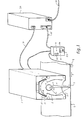
- the apparatus shown in Fig. 1 for activating photoinitiators in photosensitive substrates in for instance printing inks, lacquers and glue, which cure by treatment with UV light comprises a lamp housing 1 with reflector 2 for guiding the light beams from the lamp 4 to a focusing line 5 on the substrate, onto which a material 6 has been applied, and which moves below the lamp housing 1 at a predetermined travelling speed in direction towards the arrow 7.
- the predetermined travelling speed may be obtained either by moving the material below a stationary lamp housing or by placing the lamp housing on a robot arm such that the material need not be moved.
- an electronic ballast 30 has been inserted, said ballast being connected with the lamp by means of a cable 31.
- the travelling speed is registered by means of a measuring device 9 which is connected with a control panel 50.
- the control panel is connected with the electronic ballast which in turn is connected with the common, electric mains.
- the control panel contains circuits which deliver the signals necessary for adjusting the ballast.
- the circuits are designed such that the electronic ballast currently adjusts the energy supplied to the UV light source to a minimum which meets the desired light dosage.
- the circuits use the registered speed of the movement and information from a light measuring device placed in the light unit.
- the adjustment is made currently within a speed interval, the lower limit of which may preferably be set as the lowest speed, with which the substrate may be applied to the material. If this lower limit set is exceeded, the light units are adjusted to idle run or standby to minimize possible damages which may occur on account of heat radiation from the light units.
- the control unit may in a simple embodiment take care of providing a linear variation between the light emission and the speed of the material, but may in more refined embodiments compensate for the fact that the photoinitiator may not have such a linear activation by being provided with a table or in another way have an unlinear dependency between the control of the lighting and the registered speed.
- the object of this control which considers printing inks with an unlinear, dynamic sensitivity, i.e. that the activation level is different measured in amount of light per area unit at different light intensities, is an optimization of the lighting for the attainment of the desired curing with the least possible consumption of photoinitiators and a reduction of undesired thermal influence.
- the electronic ballast is of the type which is disclosed in US Patent No. 5,051,666 or Danish Patent No. 167 992, to which is referred in relation to the details of the design of the ballast.
- the electronic ballast itself takes solely part in the present invention as a component and is not a part thereof.
- the electronic ballast is preferably designed such that the effect transferred to the lamp is not modulated by for instance 50 Hz or 60Hz, but is on the contrary approximately constant over the time, apart from periods with a duration of less than 1 millisecond. This is different from a conventional mechanical ballast which supplies power with sine shape to the lamp, such that the effect and subsequently the light emission gets modulated with wave shape with the double frequency of the sine shape in the mains voltage.
- Fig. 5 The shape of the current delivered by a mechanical ballast and the light yield is shown in Fig. 5.
- Fig. 6 which shows lamp power and light yield by use of an electronic ballast, it is possible with the apparatus according to the invention, of which the electronic ballast is a part, to obtain a constant (with a fairly good approximation) light yield, the light emission being only reduced in the short periods of less than 1 millisecond, where the poles are changed in consideration of the construction and duration of the lamp.
- the heat radiation is further reduced by an appropriate design of the lamp housing 1.
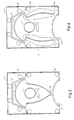
- the lamp housing is provided with a cold light mirror 10 allowing heat rays 11 from the lamp to pass over a cooling element 12, where the heat is removed by throughflowing of a cooling medium, for instance water, through cooling tubes.
- the lamp housing 1 is provided with an outlet opening in form of a window 13 with an optic filter allowing direct rays of UV light and the reflected rays of UV light to pass, whereas rays of heat and visible light are substantially reflected back.
- the cold light mirror 10 is designed as a sector of a circle and is placed concentrically with the UV light source which is preferably an elongate tubular lamp 4. UV light emitted from the lamp in direction towards the cold light mirror 10 is reflected back through the longitudinal axis of the lamp.
- the window 13 is also made with a profile like a sector of a circle, UV light emitted perpendicularly to the longitudinal direction of the lamp passing the glass surface of the window nearly perpendicularly, whereas rays of heat radiated perpendicularly to the longitudinal direction of the lamp are reflected in such a way that they do not return to the lamp, but pass beside it and up through the cold light mirror 10 and into the cooling element 12.
- a rod-shaped lens 17 is placed below the lamp 14 for deflection of the direct light beams such that they hit the window 13 nearly perpendicularly and are united with the rest of the UV part of the light down in the focusing line 5.
- the cooling element 12 which carries the cold light mirror is bent towards the lamp 4 and is at the ends provided with mirrors 25 which are directed such that the light from the lamp 4 is reflected through it.
- Light which is reflected into the lamp is admittedly absorbed partially therein but also causes new light to be generated.
- the new light is not directionally determined, but is emitted in all directions which is no drawback on account of the efficient focusing system in the lamp housing.
- the control panel 50 is in addition to a possible on-off switch and a switch for adjustment of the light dosage provided with surveillance lamps 52 which make an easy control of the function of the apparatus possible.
- the light yield decreases on account of wear and possible stains and dirt on the optics. This is normally corrected by overdimensioning of the lamp housing by for instance 30% by new lamp.
- the printer then typically operates with the lamp at full effect until it emits so little UV light that the quality of the printed matter becomes too bad.
- the present invention in connection with the electronic ballast solves on the other hand the wear problem of the lamp as well as other possible undesirable variations in the light intensity by arranging a UV light photometer in the lamp housing and connecting it to the electronic ballast which makes an automatic readjustment of the effect to the lamp.
- the light intensity on the different colours, black, silver, green blue, yellow, etc. varies a lot, but traditional lamp housings with mechanical ballast are nearly always supplied with maximum effect. Some plants may however be adjusted to 2/3 or 1/2 effect, whereby a little energy is saved.
- the present invention optimally saves energy and gives less heating of the paper, the light intensity being very accurately adjustable.
- control lamps indicate this limit, as a green lamp lights during normal operation. If the light changes to yellow, problems are beginning to arise in connection with the supply of the desired light dosage, and if the light changes into red, there are so big problems in supplying the light dosage that the travelling speed of the paper has to be reduced.
- two or three lamp housings following one another may be arranged, the electronics being synchronizable from a common control panel with buttons for manual adjustment or digital adjustment on basis of control signals from a computer.
- the control unit may as indicated in claim 11 be adapted to emit a control signal to small servomotors in the lamp housing, whereby the reflectors may be turned together and the light thereby set to a minimum.
- the light is sent from the lamp through the closed reflectors back to the lamp, which makes it easier keep the lamp in a sufficiently warm stand-by condition.
- the electronic ballast automatically increases the flow through the lamp up to 150% of normal value, which further gives the possibility of wearing the lamp completely out before it is exchanged.
- This control mechanism likewise compensates the tolerances, a rectification which always has to be done in connection with new lamps.
- the lamps comprise a set of three lamps of the colours red, yellow and green.
- Green light indicates that the lighting unit gives the desired light dosage
- yellow light indicates that the lighting unit is not completely able to deliver the desired light dosage, which is a sign that the lamp should be exchanged, but the problem may be solved straight away by reducing the speed.
- Red light indicates that the lamp is unable to deliver the desired light dosage.
- the reflectors in the lamp housing are turned simultaneously and bar the light path between the lamp and the outlet opening.
- By closing the reflectors the direction of radiation is changed in direction towards the lamp, which contributes to holding it warm, when it only receives current for stand-by operation.
- the desired light dosage may either be set as a numerical value on the control panel or it may alternatively be set by a computer controlling the machine, on which the light unit is used.
- a calibration button for the light meter built into the lamp housing may also be provided on the control panel.
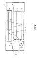
- the lamp housing is shown in a longitudinal view in Fig. 2. It will be seen that the UV light source 10 is an elongate tubular lamp placed along the housing. Above the lamp the cold light mirror and the cooling element are provided. In extension of the outlet opening a mirror 21 is arranged which substantially only reflects UV light, and in the light beam reflected from this mirror the light meter 20 registering the light yield is placed. As will be seen from Fig. 5, which shows the lamp housing in a sectional view, the cooling arrangement also comprises cooling tubes 22 placed along the side walls of the lamp housing. The suspension of the cold light mirror is such that heated air which passes the lamp 4, may pass downwards between the reflectors 2 and the outer walls of the housing and thus become cooled by means of the cooling tubes 22.
- this supply is made dependent on the relative travelling speed by controlling a control valve by means of a signal delivered from the control unit. At increasing speed the supply is increased, and at a standstill the supply is discontinued, whereby i.e. leakage and waste of nitrogen during longer periods of standstill are avoided.
Landscapes
- Engineering & Computer Science (AREA)
- Life Sciences & Earth Sciences (AREA)
- Microbiology (AREA)
- Mechanical Engineering (AREA)
- General Engineering & Computer Science (AREA)
- Supply, Installation And Extraction Of Printed Sheets Or Plates (AREA)
- Adhesives Or Adhesive Processes (AREA)
- Polymerisation Methods In General (AREA)
- Physical Or Chemical Processes And Apparatus (AREA)
- Coating Apparatus (AREA)
- Printing Methods (AREA)
Applications Claiming Priority (3)
| Application Number | Priority Date | Filing Date | Title |
|---|---|---|---|
| DK25895 | 1995-03-15 | ||
| DK25895 | 1995-03-15 | ||
| PCT/DK1996/000102 WO1996028302A1 (en) | 1995-03-15 | 1996-03-15 | A method for activating photoinitiators in photosensitive substrates and an apparatus for curing such substrates |
Publications (2)
| Publication Number | Publication Date |
|---|---|
| EP0879146A1 EP0879146A1 (en) | 1998-11-25 |
| EP0879146B1 true EP0879146B1 (en) | 2001-01-24 |
Family
ID=8091522
Family Applications (1)
| Application Number | Title | Priority Date | Filing Date |
|---|---|---|---|
| EP96906703A Expired - Lifetime EP0879146B1 (en) | 1995-03-15 | 1996-03-15 | A method for activating photoinitiators in photosensitive substrates and an apparatus for curing such substrates |
Country Status (9)
| Country | Link |
|---|---|
| US (1) | US5945680A (da) |
| EP (1) | EP0879146B1 (da) |
| JP (1) | JPH11501875A (da) |
| AT (1) | ATE198854T1 (da) |
| AU (1) | AU5001396A (da) |
| DE (1) | DE69611697T2 (da) |
| DK (1) | DK0879146T3 (da) |
| ES (1) | ES2155600T3 (da) |
| WO (1) | WO1996028302A1 (da) |
Families Citing this family (20)
| Publication number | Priority date | Publication date | Assignee | Title |
|---|---|---|---|---|
| US6333509B1 (en) * | 1996-07-09 | 2001-12-25 | Lumpp & Consultants | Electromagnetic radiation transmitter/reflector device, apparatus and process implementing such a device |
| ATE224523T1 (de) * | 1997-05-26 | 2002-10-15 | Uviterno Ag | Vorrichtung zum bestrahlen eines substrats mittels uv-strahlen und verfahren zum betrieb der vorrichtung |
| DE19810455C2 (de) | 1998-03-11 | 2000-02-24 | Michael Bisges | Kaltlicht-UV-Bestrahlungsvorrichtung |
| DE19916474A1 (de) * | 1999-04-13 | 2000-10-26 | Ist Metz Gmbh | Bestrahlungsgerät |
| DE10115066B4 (de) * | 2001-03-27 | 2012-10-04 | Leica Biosystems Nussloch Gmbh | Vorrichtung zum Trocknen lösungsmittelbasierender Tinte |
| US6550905B1 (en) | 2001-11-19 | 2003-04-22 | Dotrix N.V. | Radiation curable inkjet ink relatively free of photoinitiator and method and apparatus of curing the ink |
| US6739716B2 (en) | 2002-06-10 | 2004-05-25 | Océ Display Graphics Systems, Inc. | Systems and methods for curing a fluid |
| DE10241163B4 (de) * | 2002-09-05 | 2006-05-18 | Singulus Technologies Ag | Vorrichtung und Verfahren zum Herstellen von optischen Datenträgern insbesondere durch Verkleben von Rohlingen mittels UV-härtbaren Klebern |
| AU2003273789A1 (en) | 2002-10-29 | 2004-05-25 | Knud Andreasen | Cooling of devices for uv hardening |
| JP3864903B2 (ja) * | 2002-12-13 | 2007-01-10 | コニカミノルタホールディングス株式会社 | インクジェットプリンタ |
| US7055990B2 (en) * | 2004-05-06 | 2006-06-06 | Fusion Uv Systems, Inc. | Apparatus and method for providing substantially uniform radiation of a three-dimensional object with at least one curved surface |
| US20070187027A1 (en) * | 2006-02-16 | 2007-08-16 | Delaware Capital Formation, Inc. | Curing system and method of curing |
| US20070189018A1 (en) * | 2006-02-16 | 2007-08-16 | Delaware Capital Formation, Inc. | Curing system and method of curing |
| EP1967284A3 (de) * | 2007-03-06 | 2008-12-17 | Ist Metz Gmbh | Verfahren und Vorrichtung zur UV-Strahlungshärtung von Substratbeschichtungen |
| CH700039A1 (de) | 2008-12-01 | 2010-06-15 | Uviterno Ag | Vorrichtung zum bestrahlen eines substrats |
| US20100154244A1 (en) * | 2008-12-19 | 2010-06-24 | Exfo Photonic Solutions Inc. | System, Method, and Adjustable Lamp Head Assembly, for Ultra-Fast UV Curing |
| GB2480693A (en) * | 2010-05-28 | 2011-11-30 | Nordson Corp | Ultra violet light emitting diode curing assembly |
| CN104298014B (zh) * | 2014-10-14 | 2017-04-12 | 合肥京东方光电科技有限公司 | 应用于显示面板的光源系统、紫外固化装置及固化方法 |
| DE102015013067B4 (de) * | 2015-07-10 | 2017-10-12 | Koenig & Bauer Ag | Druckmaschine mit UV-Bestrahlungsmodul |
| DE102016211511A1 (de) | 2016-06-27 | 2017-12-28 | Carl Zeiss Smt Gmbh | Beleuchtungseinheit für die Mikrolithographie |
Family Cites Families (13)
| Publication number | Priority date | Publication date | Assignee | Title |
|---|---|---|---|---|
| US3733709A (en) * | 1971-05-06 | 1973-05-22 | Sun Chemical Corp | Reflector and cooling means therefor |
| US4055769A (en) * | 1972-03-21 | 1977-10-25 | Conrad Sander | Method and apparatus for curing, a coating on a substrate |
| US4033263A (en) * | 1974-12-12 | 1977-07-05 | Harris Corporation | Wide range power control for electric discharge lamp and press using the same |
| US4048490A (en) * | 1976-06-11 | 1977-09-13 | Union Carbide Corporation | Apparatus for delivering relatively cold UV to a substrate |
| US4084490A (en) * | 1977-02-14 | 1978-04-18 | Owens-Illinois, Inc. | Container bottom cutting apparatus and method |
| US4563589A (en) * | 1984-01-09 | 1986-01-07 | Scheffer Herbert D | Ultraviolet curing lamp device |
| CH660489A5 (de) * | 1984-08-31 | 1987-04-30 | Bernhard Glaus | Verfahren und vorrichtung zum aushaerten polymerisierbarer beschichtungsmassen auf nicht textilen substraten. |
| US4798960A (en) * | 1986-07-17 | 1989-01-17 | Ferd. Ruesch Ag | Device for the treatment of substances by UV radiation |
| DK89388D0 (da) * | 1988-02-19 | 1988-02-19 | Silver Gruppen Prod As | Elektronisk ballast |
| JPH0675200B2 (ja) * | 1990-05-18 | 1994-09-21 | 株式会社オーク製作所 | 露光装置用冷却構造 |
| US5204534A (en) * | 1990-11-07 | 1993-04-20 | Dubuit Jean Louis | Ultraviolet radiation drying oven and drying enclosure thereof |
| JP3173033B2 (ja) * | 1991-03-20 | 2001-06-04 | ソニー株式会社 | 放光装置 |
| GB9116120D0 (en) * | 1991-07-25 | 1991-09-11 | G E W Ec Ltd | U.v.dryers |
-
1996
- 1996-03-15 ES ES96906703T patent/ES2155600T3/es not_active Expired - Lifetime
- 1996-03-15 WO PCT/DK1996/000102 patent/WO1996028302A1/en not_active Ceased
- 1996-03-15 US US08/913,470 patent/US5945680A/en not_active Expired - Lifetime
- 1996-03-15 AT AT96906703T patent/ATE198854T1/de not_active IP Right Cessation
- 1996-03-15 EP EP96906703A patent/EP0879146B1/en not_active Expired - Lifetime
- 1996-03-15 AU AU50013/96A patent/AU5001396A/en not_active Abandoned
- 1996-03-15 JP JP8527188A patent/JPH11501875A/ja active Pending
- 1996-03-15 DK DK96906703T patent/DK0879146T3/da active
- 1996-03-15 DE DE69611697T patent/DE69611697T2/de not_active Expired - Fee Related
Also Published As
| Publication number | Publication date |
|---|---|
| US5945680A (en) | 1999-08-31 |
| DE69611697D1 (de) | 2001-03-01 |
| DK0879146T3 (da) | 2001-06-18 |
| WO1996028302A1 (en) | 1996-09-19 |
| EP0879146A1 (en) | 1998-11-25 |
| ATE198854T1 (de) | 2001-02-15 |
| JPH11501875A (ja) | 1999-02-16 |
| ES2155600T3 (es) | 2001-05-16 |
| DE69611697T2 (de) | 2001-08-16 |
| AU5001396A (en) | 1996-10-02 |
Similar Documents
| Publication | Publication Date | Title |
|---|---|---|
| EP0879146B1 (en) | A method for activating photoinitiators in photosensitive substrates and an apparatus for curing such substrates | |
| CA1317908C (en) | Apparatus and method for curing photosensitive coatings | |
| KR100460675B1 (ko) | 자외선조사장치 | |
| GB2349684A (en) | Lamp Assembly | |
| FI934280A0 (fi) | Foerfarande och apparat foer sterilisering av kartonger | |
| CA2198713A1 (en) | Method and apparatus for calibrating a laser wavelength control mechanism | |
| CA2474832A1 (en) | Apparatus and methods relating to wavelength conditioning of illumination | |
| MX9710461A (es) | Control de un campo heliostatico en una planta de energia solar. | |
| WO2006064363A1 (en) | Process and apparatus for the production of collimated uv rays for photolithographic transfer | |
| GB2407371A (en) | A lamp assembly with additional reflectors to reduce the angular spread of radiation | |
| GB2070327A (en) | Method and apparatus for annealing semiconductors | |
| CA2048825A1 (en) | Stabilized fluorescent lamp for a document scanning system | |
| EP0754976A3 (en) | Surface activating process, and device and lamp for performing said process | |
| JP3760416B2 (ja) | 工作材料試料の処理方法および光および耐候検査装置 | |
| US4873470A (en) | Programmable ultraviolet lamp control system | |
| JPH09147805A (ja) | 棒状ランプの冷却方法および光照射器 | |
| NZ501693A (en) | A device for illuminating a defined area | |
| KR20010072413A (ko) | 글래이징 패널의 릴리징 | |
| US5874981A (en) | Combined pulse-width and amplitude modulation of exposing laser beam for thermal dye transfer | |
| JPH0624670B2 (ja) | 紫外線光源装置 | |
| CA1264312A (en) | Illumination system in a projection copier | |
| JPH09266159A (ja) | 露光量制御装置 | |
| JP2507115B2 (ja) | 光ビ―ム加熱機 | |
| CN223282948U (zh) | 一种防水色温校正聚光灯 | |
| JPS5740277A (en) | Exposure control device of copying machine |
Legal Events
| Date | Code | Title | Description |
|---|---|---|---|
| PUAI | Public reference made under article 153(3) epc to a published international application that has entered the european phase |
Free format text: ORIGINAL CODE: 0009012 |
|
| 17P | Request for examination filed |
Effective date: 19970822 |
|
| AK | Designated contracting states |
Kind code of ref document: A1 Designated state(s): AT BE CH DE DK ES FR GB IT LI NL SE |
|
| 17Q | First examination report despatched |
Effective date: 19990125 |
|
| GRAG | Despatch of communication of intention to grant |
Free format text: ORIGINAL CODE: EPIDOS AGRA |
|
| GRAG | Despatch of communication of intention to grant |
Free format text: ORIGINAL CODE: EPIDOS AGRA |
|
| GRAG | Despatch of communication of intention to grant |
Free format text: ORIGINAL CODE: EPIDOS AGRA |
|
| GRAH | Despatch of communication of intention to grant a patent |
Free format text: ORIGINAL CODE: EPIDOS IGRA |
|
| RAP1 | Party data changed (applicant data changed or rights of an application transferred) |
Owner name: NLM-COMBINEERING APS |
|
| GRAH | Despatch of communication of intention to grant a patent |
Free format text: ORIGINAL CODE: EPIDOS IGRA |
|
| GRAA | (expected) grant |
Free format text: ORIGINAL CODE: 0009210 |
|
| AK | Designated contracting states |
Kind code of ref document: B1 Designated state(s): AT BE CH DE DK ES FR GB IT LI NL SE |
|
| REF | Corresponds to: |
Ref document number: 198854 Country of ref document: AT Date of ref document: 20010215 Kind code of ref document: T |
|
| REG | Reference to a national code |
Ref country code: CH Ref legal event code: EP |
|
| REF | Corresponds to: |
Ref document number: 69611697 Country of ref document: DE Date of ref document: 20010301 |
|
| ITF | It: translation for a ep patent filed | ||
| ET | Fr: translation filed | ||
| REG | Reference to a national code |
Ref country code: CH Ref legal event code: NV Representative=s name: A. BRAUN, BRAUN, HERITIER, ESCHMANN AG PATENTANWAE |
|
| REG | Reference to a national code |
Ref country code: ES Ref legal event code: FG2A Ref document number: 2155600 Country of ref document: ES Kind code of ref document: T3 |
|
| REG | Reference to a national code |
Ref country code: DK Ref legal event code: T3 |
|
| PLBE | No opposition filed within time limit |
Free format text: ORIGINAL CODE: 0009261 |
|
| STAA | Information on the status of an ep patent application or granted ep patent |
Free format text: STATUS: NO OPPOSITION FILED WITHIN TIME LIMIT |
|
| REG | Reference to a national code |
Ref country code: GB Ref legal event code: IF02 |
|
| 26N | No opposition filed | ||
| REG | Reference to a national code |
Ref country code: CH Ref legal event code: PFA Owner name: NLM-COMBINEERING APS Free format text: NLM-COMBINEERING APS#RUNDFORBIVEJ 293#2850 NAERUM (DK) -TRANSFER TO- NLM-COMBINEERING APS#RUNDFORBIVEJ 293#2850 NAERUM (DK) |
|
| PGFP | Annual fee paid to national office [announced via postgrant information from national office to epo] |
Ref country code: ES Payment date: 20090330 Year of fee payment: 14 Ref country code: DK Payment date: 20090313 Year of fee payment: 14 Ref country code: AT Payment date: 20090331 Year of fee payment: 14 |
|
| PGFP | Annual fee paid to national office [announced via postgrant information from national office to epo] |
Ref country code: NL Payment date: 20090331 Year of fee payment: 14 |
|
| PGFP | Annual fee paid to national office [announced via postgrant information from national office to epo] |
Ref country code: GB Payment date: 20090324 Year of fee payment: 14 |
|
| PGFP | Annual fee paid to national office [announced via postgrant information from national office to epo] |
Ref country code: BE Payment date: 20090331 Year of fee payment: 14 |
|
| PGFP | Annual fee paid to national office [announced via postgrant information from national office to epo] |
Ref country code: SE Payment date: 20090324 Year of fee payment: 14 Ref country code: IT Payment date: 20090330 Year of fee payment: 14 Ref country code: FR Payment date: 20090330 Year of fee payment: 14 Ref country code: DE Payment date: 20090331 Year of fee payment: 14 |
|
| PGFP | Annual fee paid to national office [announced via postgrant information from national office to epo] |
Ref country code: CH Payment date: 20090401 Year of fee payment: 14 |
|
| BERE | Be: lapsed |
Owner name: *NLM-COMBINEERING APS Effective date: 20100331 |
|
| REG | Reference to a national code |
Ref country code: NL Ref legal event code: V1 Effective date: 20101001 |
|
| REG | Reference to a national code |
Ref country code: CH Ref legal event code: PL |
|
| EUG | Se: european patent has lapsed | ||
| REG | Reference to a national code |
Ref country code: DK Ref legal event code: EBP |
|
| GBPC | Gb: european patent ceased through non-payment of renewal fee |
Effective date: 20100315 |
|
| PG25 | Lapsed in a contracting state [announced via postgrant information from national office to epo] |
Ref country code: AT Free format text: LAPSE BECAUSE OF NON-PAYMENT OF DUE FEES Effective date: 20100315 |
|
| REG | Reference to a national code |
Ref country code: FR Ref legal event code: ST Effective date: 20101130 |
|
| PG25 | Lapsed in a contracting state [announced via postgrant information from national office to epo] |
Ref country code: NL Free format text: LAPSE BECAUSE OF NON-PAYMENT OF DUE FEES Effective date: 20101001 Ref country code: FR Free format text: LAPSE BECAUSE OF NON-PAYMENT OF DUE FEES Effective date: 20100331 |
|
| PG25 | Lapsed in a contracting state [announced via postgrant information from national office to epo] |
Ref country code: LI Free format text: LAPSE BECAUSE OF NON-PAYMENT OF DUE FEES Effective date: 20100331 Ref country code: DE Free format text: LAPSE BECAUSE OF NON-PAYMENT OF DUE FEES Effective date: 20101001 Ref country code: CH Free format text: LAPSE BECAUSE OF NON-PAYMENT OF DUE FEES Effective date: 20100331 Ref country code: BE Free format text: LAPSE BECAUSE OF NON-PAYMENT OF DUE FEES Effective date: 20100331 |
|
| PG25 | Lapsed in a contracting state [announced via postgrant information from national office to epo] |
Ref country code: GB Free format text: LAPSE BECAUSE OF NON-PAYMENT OF DUE FEES Effective date: 20100315 Ref country code: IT Free format text: LAPSE BECAUSE OF NON-PAYMENT OF DUE FEES Effective date: 20100315 |
|
| REG | Reference to a national code |
Ref country code: ES Ref legal event code: FD2A Effective date: 20110419 |
|
| PG25 | Lapsed in a contracting state [announced via postgrant information from national office to epo] |
Ref country code: DK Free format text: LAPSE BECAUSE OF NON-PAYMENT OF DUE FEES Effective date: 20100331 |
|
| PG25 | Lapsed in a contracting state [announced via postgrant information from national office to epo] |
Ref country code: ES Free format text: LAPSE BECAUSE OF NON-PAYMENT OF DUE FEES Effective date: 20110404 |
|
| PG25 | Lapsed in a contracting state [announced via postgrant information from national office to epo] |
Ref country code: ES Free format text: LAPSE BECAUSE OF NON-PAYMENT OF DUE FEES Effective date: 20100316 |
|
| PG25 | Lapsed in a contracting state [announced via postgrant information from national office to epo] |
Ref country code: SE Free format text: LAPSE BECAUSE OF NON-PAYMENT OF DUE FEES Effective date: 20100316 |