EP0878121A1 - Automatisch lenkbare Erntemaschine - Google Patents
Automatisch lenkbare Erntemaschine Download PDFInfo
- Publication number
- EP0878121A1 EP0878121A1 EP98104759A EP98104759A EP0878121A1 EP 0878121 A1 EP0878121 A1 EP 0878121A1 EP 98104759 A EP98104759 A EP 98104759A EP 98104759 A EP98104759 A EP 98104759A EP 0878121 A1 EP0878121 A1 EP 0878121A1
- Authority
- EP
- European Patent Office
- Prior art keywords
- harvesting machine
- crop
- machine according
- edge
- cutting
- Prior art date
- Legal status (The legal status is an assumption and is not a legal conclusion. Google has not performed a legal analysis and makes no representation as to the accuracy of the status listed.)
- Granted
Links
- 238000003306 harvesting Methods 0.000 title claims description 51
- 230000011514 reflex Effects 0.000 claims description 6
- 238000012545 processing Methods 0.000 claims description 4
- 239000000523 sample Substances 0.000 claims description 2
- 238000012935 Averaging Methods 0.000 claims 1
- 238000000034 method Methods 0.000 abstract description 3
- 238000011156 evaluation Methods 0.000 description 2
- 239000012530 fluid Substances 0.000 description 2
- 241001124569 Lycaenidae Species 0.000 description 1
- 230000015572 biosynthetic process Effects 0.000 description 1
- 238000012937 correction Methods 0.000 description 1
- 238000009499 grossing Methods 0.000 description 1
- 230000001788 irregular Effects 0.000 description 1
- 238000013507 mapping Methods 0.000 description 1
- 230000001105 regulatory effect Effects 0.000 description 1
Images

Classifications
-
- A—HUMAN NECESSITIES
- A01—AGRICULTURE; FORESTRY; ANIMAL HUSBANDRY; HUNTING; TRAPPING; FISHING
- A01D—HARVESTING; MOWING
- A01D41/00—Combines, i.e. harvesters or mowers combined with threshing devices
- A01D41/12—Details of combines
- A01D41/127—Control or measuring arrangements specially adapted for combines
- A01D41/1278—Control or measuring arrangements specially adapted for combines for automatic steering
-
- Y—GENERAL TAGGING OF NEW TECHNOLOGICAL DEVELOPMENTS; GENERAL TAGGING OF CROSS-SECTIONAL TECHNOLOGIES SPANNING OVER SEVERAL SECTIONS OF THE IPC; TECHNICAL SUBJECTS COVERED BY FORMER USPC CROSS-REFERENCE ART COLLECTIONS [XRACs] AND DIGESTS
- Y10—TECHNICAL SUBJECTS COVERED BY FORMER USPC
- Y10S—TECHNICAL SUBJECTS COVERED BY FORMER USPC CROSS-REFERENCE ART COLLECTIONS [XRACs] AND DIGESTS
- Y10S56/00—Harvesters
- Y10S56/15—Condition responsive
Definitions
- the invention relates to an automatically steerable harvesting machine consisting of a self-propelled Vehicle and a cutter / mower carried by this, which a locating device for Scanning a crop edge for steering orientation.
- Such a harvesting machine is known from DE 24 55 836. With this harvester Crop edge at a certain distance in front of the cutting / mower by means of reflex location Light rays or ultrasonic waves are scanned without contact.
- the automatically controlled harvesting machine (self-propelled vehicle with attached Cutting / mower) has at least one known locating device for scanning the Harvest edge on For automatic steering, the location signals in a known manner Regulator (e.g. an electronic circuit, or a microcontroller) fed where this are processed.
- the controller which in addition to the location signals in a known manner Actual wheel lock angle values of the steerable wheels of the harvesting machine acts above that Means familiar to those skilled in the art for adjusting the steerable wheels.
- Such means are, for example a hydraulic steering cylinder, which has an electrically actuated hydraulic control valve hydraulic fluid is regulated.
- the invention is not based on harvesters steerable wheels, but also for harvesting machines with a crawler track applicable.
- the controller for automatic steering in the harvesting machine according to the invention two or more referring to different scanning distances in front of the cutting / mower Locating signals processed, is an automatically steerable harvester with a stable working Regulation has been created that can be used reliably.
- From two or more at different scanning distances in front of the cutting / mower referencing location signals can be the direction angle between the crop edge, which in the Usually runs at least approximately in a straight line, and the harvesting machine longitudinal axis is quite precise determine and use for automatic steering control.
- the Harvester longitudinal axis guided parallel to the edge of the crop i.e. the scheme tries the above to minimize said direction angle to zero.
- the harvesting machine has two Locating devices for scanning the crop edge at two different distances, whereby the one the crop edge in the long range, for example 8-10 m in front of the cutting / mower and the others the edge of the crop in the immediate vicinity immediately before or in the catchment area of the Cutting / mower scans.
- the harvesting machine has a Location device on which is pivotable about a horizontal axis, the Location device depending on the swivel angle of the crop edge at a different distance from the Cutting / mower scans.
- a second locating device can be dispensed with here.
- the second locating device is in particular for determining the distance between the Cutting / mower boundary edge and the crop edge designed. This can be used to determine and regulation of the cutting / mower utilization. This can be combined with a Online yield recording also for creating a more precise area determination and from it resulting more precise yield mapping can be used.
- the location signals of the second location device serve as a correction signal for one Autopilot, primarily based on the signals from the first locating device (OV1) for the Remote sensing directs.
- a weighting i.e. the influence on the automatic steering, the location signals (far, near; OS1, OS2) can be carried out depending on the driving speed.
- the person skilled in the art can also use a digital camera instead of a reflex locating device, which is arranged above the crop and is inclined forwardly towards the ground.
- the recording area of the camera lying in front of the cutting / mowing unit is evaluated for scanning the edge of the crop using digital image processing.
- the edge of the crop can be determined at only one point in the recording area of the camera and the position of this point in relation to the harvesting machine / cutting / mowing device can be used as a location signal for automatic steering.
- the crop edge can be determined at two or more points in the recording area of the camera at several points and the position of these points can be used for automatic steering.
- the positions of the crop edge scanned with at least one of the two locating devices during the journey are additionally stored continuously in a ring memory for determining a crop edge profile and the controller for automatic steering also processes this crop edge profile.
- the scanned crop edge course can be averaged over a certain time window by moving averages.
- the harvesting machine - in this case a self-propelled combine harvester (1) with cutting unit (2) - has two locating devices (OV1, OV2) for scanning the edge of the crop (EK) at two different distances (A1, A2) in front of the cutting unit (2).
- the scanning point of the crop edge (EK) by the first locating device lies in Long range "3 to 15 m, preferably 8 to 10 m, in front of the cutting unit (2).
- this location device (OV1) the person skilled in the art can, for example, use a reflex location device which is arranged above the crop (EG) and its location rays (OS1) run slightly inclined towards the ground.
- the locating beams (OS1) scan the crop edge (EK) on both sides.
- this reflex locating device (OV1) is formed by a laser scanner with laser beam transmitting / receiving devices, whose laser locating beams (OS1) are periodically pivoted in a certain angular range
- the person skilled in the art can also use an ultrasonic sensor with ultrasonic transmitters / receivers.
- the further configuration of these known reflex locating devices as well as the evaluation of the reflected locating beams in order to recognize the boundary between the mown and the uncut crop are not to be discussed in more detail here.
- those skilled in the art can rely on methods and devices known in the art.
- the locating device (OV1) is preferably mounted directly on the cutting unit (2) on the left or right cutting edge of the cutting / mower deck (SK). So that runs Center beam of the locating device (OV1) aligned with the cutting / mower boundary edge (SK). In one embodiment, not shown, this locating device (OV1) on the self-driving vehicle, for example on the driver's cabin. In each The position of the locating device (OV1) is determined by geometric relationships in the case Evaluation of the location signals (OS1) and processing in the controller for the automatic Steering taken into account, the arrangement of the locating device (OV1) directly on the Cutting / mower boundary edge (SK) particularly cheap and easy to determine provides geometric relationships.
- the second locating device (OV2) for the Short range " is - in the example shown here - arranged on the right cutting edge of the cutting / mower deck (SK). It scans the distance between the cutting edge / mower border (SK) and the crop edge (EK) with an ultrasonic sensor.
- the ultrasonic sensor the person skilled in the art can also use a probe bracket (not shown) that can be deflected mechanically from the edge of the crop, the deflection of which is measured.
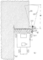
- FIG. 2 shows a side view of the harvesting machine, on which it is visible where the first Location device (OV1) is arranged on the cutting unit (2) and like the location beams (OS1) run.
- OV1 first Location device
- OS1 location beams
- the controller (3) receives the location signals (OS1, OS2) of the two Locating devices (OV1, OV2), the actual steering angle and a signal for the Vehicle speed.
- the controller determines using an implemented control algorithm (3) from this a control signal for an electrically actuable, hydraulic control valve that the Hydraulic fluid is applied to the steering cylinder to adjust the steerable wheels.
Landscapes
- Life Sciences & Earth Sciences (AREA)
- Environmental Sciences (AREA)
- Guiding Agricultural Machines (AREA)
- Harvester Elements (AREA)
- Combines (AREA)
Abstract
Description
Außerdem ist es vorgesehen, die mit mindestens einer der beiden Ortungsvorrichtungen während der Fahrt abgetasteten Positionen der Erntegutkante zusätzlich fortlaufend in einem Ringspeicher zur Ermittlung eines Erntegutkantenverlaufes abzuspeichern und diesen Erntegutkantenverlauf von dem Regler zur automatischen Lenkung mitzuverarbeiten. Der abgetastete Erntegutkantenverlauf kann hierzu jeweils durch gleitende Mittelwertbildung über ein bestimmtes Zeitfenster gemittelt werden.
- Fig.1
- eine Draufsicht auf die automatisch lenkbare Erntemaschine im Ernteeinsatz,
- Fig.2
- eine Seitenansicht der Erntemaschine,
- Fig.3
- eine schematische Darstellung des Reglers und der Lenkmittel.
Auf die weitere Ausgestaltung dieser an sich bekannten Reflex-Ortungsvorrichtungen sowie auf die Auswertung der reflektierten Ortungsstrahlen, um die Grenze zwischen dem gemähten und dem ungemähten Erntegut zu erkennen, soll hier nicht näher eingegangen werden. Hier kann der Fachmann sich aufim Stand der Technik bekannte Verfahren und Vorrichtungen stützten.
Claims (22)
- Automatisch lenkbare Erntemaschine bestehend aus einem selbstfahrenden Fahrzeug (1) und einem vom diesem getragenen Schneind/-Mähwerk (2), die eine an sich bekannte Ortungsvorrichtung (OV1) zum Abtasten der Erntegutkante (EK), insbesondere die Grenze zwischen gemähtem und ungemähtem Erntegut, aufweist, wobei die von der Ortungsvorrichtung (OV1) erzeugten Ortungssignale (OS1) von einem Regler (3) verarbeitet werden und über bekannte Mittel der automatischen Lenkung dienen,
dadurch gekennzeichnet,
daß die Erntegutkante (EK) in mindestens zwei unterschiedlichen Abständen (A1, A2) vor dem Schneid/-Mähwerk (2) abgetastet wird, und von dem Regler (3) mindestens zwei zu unterschiedlichen Abtastabständen (A1, A2) vor dem Schneid/-Mähwerk (2) referierende Ortungssignale (OS1, OS2) verarbeitet werden und über bekannte Mittel zur automatischen Lenkung dienen. - Automatisch lenkbare Erntemaschine nach Anspruch 1,
dadurch gekennzeichnet,
daß aus mindestens zwei zu unterschiedlichen Abtastabständen (A1,A2) vor dem Schneid/-Mähwerk (2) referierenden Ortungssignalen (OS1,OS2) der Richtungswinkel zwischen der Erntemaschinen-Längsachse und der Erntegutkante (EK) und/ oder der Abstand zwischen der linken bzw. rechten Schneid/-Mähwerks-Begrenzungskante (SK) und der Erntegutkante (EK) ermittelt und der so ermittelte Richtungswinkel und/ oder Abstand der automatischen Lenkung dienen. - Automatisch lenkbare Erntemaschine nach einem der Ansprüche 1 oder 2,
dadurch gekennzeichnet,
daß die Erntemaschine mindestens zwei Ortungsvorrichtungen (OV1, OV2) zum Abtasten der Erntegutkante (EK) aufweist, wobei die Ortungsvorrichtungen (OV1,OV2) die Erntegutkante (EK) jeweils in einem unterschiedlichen Abstand (A1,A2) vor dem Schneid/-Mähwerk (2) abtasten. - Automatisch lenkbare Erntemaschine nach Anspruch 3,
dadurch gekennzeichnet,
daß die erste Ortungsvorrichtung (OV1) von einer mit Ortungsstrahlen (OS1) berührungslos arbeitenden Reflex-Ortungsvorrichtung gebildet ist, die oberhalb des Erntegutes angeordnet ist und deren Ortungsstrahlen (OS1) nach vorn geneigt zum Boden verlaufen, wobei die Ortungsstrahlen (OS1) zu beiden Seiten der abzutastenden Erntekante (EK) verlaufen und die Ortungsstrahlen (OS1) die Erntegutkante in einem Abstand (A1) zwischen 3 m und 15 m vor dem Schneid/-Mähwerk (2), vorzugsweise zwischen 8 m und 10 m, abtasten. - Automatisch lenkbare Erntemaschine nach Anspruch 4,
dadurch gekennzeichnet,
daß die erste Ortungsvorrichtung (OV1) ein Laserscanner mit Laserstrahlsende/-Empfangseinrichtungen ist, dessen Laser-Ortungstrahlen (OS1) periodisch in einem bestimmten Winkelbereich verschwenkt werden. - Automatisch lenkbare Erntemaschine nach Anspruch 4,
dadurch gekennzeichnet,
daß die erste Ortungsvorrichtung (OV1) ein Ultraschallsensor mit Ultraschallsender/-Empfangseinrichtungen ist. - Automatisch lenkbare Erntemaschine nach einem der Ansprüche 3 bis 6,
dadurch gekennzeichnet,
daß die erste Ortungsvorrichtung (OV1) an dem Schneid/-Mähwerk (2) montiert ist. - Automatisch lenkbare Erntemaschine nach Anspruch 7,
dadurch gekennzeichnet,
daß die erste Ortungseinrichtung (OV1) direkt an der linken bzw. rechten Schneid/-Mähwerks-Begrenzungskante (SK) angeordnet ist. - Automatisch lenkbare Erntemaschine nach einem der Ansprüche 3 bis 6,
dadurch gekennzeichnet,
daß die erste Ortungseinrichtung (OV1) an dem selbstfahrenden Fahrzeug (1) angeordnet ist. - Automatisch lenkbare Erntemaschine nach einem der vorstehenden Ansprüche 3 bis 9,
dadurch gekennzeichnet,
daß die zweite Ortungsvorrichtung (OV2) die Erntegutkante (EK) im Einzugsbereich des Schneid/-Mähwerks (2) abtastet. - Automatisch lenkbare Erntemaschine nach Anspruch 10,
dadurch gekennzeichnet,
daß die zweite Ortungsvorrichtung (OV2) an der linken bzw. rechten Schneid/-Mähwerks-Begrenzungskante (SK) des Schneid/-Mähwerks (2) angeordnet ist und den Abstand zwischen der Schneid/-Mähwerks-Begrenzungskante (SK) und der Erntegutkante (EK) abtastet. - Automatisch lenkbare Erntemaschine nach einem der Ansprüche 10 oder 11,
dadurch gekennzeichnet,
daß die zweite Ortungsvorrichtung (OV2) von einem Ultraschallsensor mit Ultraschallsende/-Empfangseinrichtungen ist. - Automatisch lenkbare Erntemaschine nach einem der Ansprüche 10 oder 11,
dadurch gekennzeichnet,
daß die zweite Ortungsvorrichtung (OV2) von einem mechanisch gegenüber der Erntegutkante (EK) auslenkbaren Tastbügel gebildet ist, dessen Auslenkung gemessen wird. - Automatisch lenkbare Erntemaschine nach einem der Ansprüche 11 bis 13,
dadurch gekennzeichnet,
daß die zweite Ortungsvorrichtung (OV2) zusätzlich ein Signal für die Schneid/-Mähwerks-Auslastung liefert. - Automatisch lenkbare Erntemaschine nach einem der vorstehenden Ansprüche,
dadurch gekennzeichnet,
daß die Erntemaschine eine um eine horizontale Achse schwenkbare Ortungsvorrichtung (OV1) aufweist, wobei die Ortungsvorrichtung (OV1) je nach Schwenkwinkel die Erntegutkante (EK) in einem anderen Abstand (A1,A2) vor dem Schneid/-Mähwerk (2) abtastet. - Automatisch lenkbare Erntemaschine nach Anspruch 15,
dadurch gekennzeichnet,
daß die Ortungsvorrichtung (OV1) für die Nah- und Fernabtastung der Erntegutkante (EK) auf zwei Schwenkwinkel einstellbar ist. - Automatisch lenkbare Erntemaschine nach Anspruch 15,
dadurch gekennzeichnet,
daß die Ortungsvorrichtung (OV1) stufenlos verschwenkbar ist, wobei die Erntegutkante (EK) in einem Abstandsbereich (A1-A2) vor dem Schneid/-Mähwerk (2) stufenlos abtastbar ist. - Automatisch lenkbare Erntemaschine nach einem der vorstehenden Ansprüche,
dadurch gekennzeichnet,
daß die Erntemaschine eine Ortungsvorrichtung (OV1) in Form einer digitalen Kamera aufweist, die oberhalb des Erntegutes angeordnet ist und nach vorn geneigt zum Boden ausgerichtet ist, wobei der vor dem Schneid/-Mähwerk (2) liegende Aufnahmebereich der Kamera zum Abtasten der Erntegutkante (EK) mittels digitaler Bildverarbeitung ausgewertet wird. - Automatisch lenkbare Erntemaschine nach Anspruch 18,
dadurch gekennzeichnet,
daß die Erntegutkante (EK) an einem Punkt im Aufnahmebereich der Kamera ermittelt und die Lage dieses Punktes als Ortungssignal verwendet wird. - Automatisch lenkbare Erntemaschine nach Anspruch 18,
dadurch gekennzeichnet,
daß der Erntegutkantenverlauf im Aufnahmebereich der Kamera an mehreren Punkten ermittelt und diese Punkte als Ortungssignale verwendet werden. - Automatisch lenkbare Erntemaschine nach einem der vorstehenden Ansprüche,
dadurch gekennzeichnet,
daß die mit mindestens einer Ortungsvorrichtung (OV1,OV2) während der Fahrt abgetasteten Positionen der Erntegutkante zusätzlich fortlaufend in einem Ringspeicher zur Erzeugung eines Erntegutkantenverlaufes abgespeichert werden und dieser Erntegutkantenverlaufvon dem Regler zur automatischen Lenkung verarbeitet wird. - Automatisch lenkbare Erntemaschine nach einem der vorstehenden Ansprüche,
dadurch gekennzeichnet,
daß der abgetastete Erntegutkantenverlauf jeweils durch gleitende Mittelwertbildung über ein bestimmtes Zeitfenster gemittelt wird und der gemittelte Erntegutkantenverlauf von dem Regler zur automatischen Lenkung verarbeitet wird.
Applications Claiming Priority (2)
| Application Number | Priority Date | Filing Date | Title |
|---|---|---|---|
| DE19719939 | 1997-05-13 | ||
| DE19719939A DE19719939A1 (de) | 1997-05-13 | 1997-05-13 | Automatisch lenkbare Erntemaschine |
Publications (3)
| Publication Number | Publication Date |
|---|---|
| EP0878121A1 true EP0878121A1 (de) | 1998-11-18 |
| EP0878121B1 EP0878121B1 (de) | 2003-06-04 |
| EP0878121B2 EP0878121B2 (de) | 2006-04-05 |
Family
ID=7829288
Family Applications (1)
| Application Number | Title | Priority Date | Filing Date |
|---|---|---|---|
| EP98104759A Expired - Lifetime EP0878121B2 (de) | 1997-05-13 | 1998-03-17 | Automatisch lenkbare Erntemaschine |
Country Status (5)
| Country | Link |
|---|---|
| US (1) | US6101795A (de) |
| EP (1) | EP0878121B2 (de) |
| DE (2) | DE19719939A1 (de) |
| DK (1) | DK0878121T4 (de) |
| UA (1) | UA44819C2 (de) |
Cited By (7)
| Publication number | Priority date | Publication date | Assignee | Title |
|---|---|---|---|---|
| EP0906720A1 (de) * | 1997-10-04 | 1999-04-07 | CLAAS Selbstfahrende Erntemaschinen GmbH | Vorrichtung und Verfahren zur berührungslosen Erkennung von Bearbeitungsgrenzen oder entsprechenden Leitgrössen |
| EP1266553A2 (de) | 2001-06-16 | 2002-12-18 | Deere & Company | Einrichtung zur selbsttätigen Lenkung eines landwirtschaftlichen Arbeitsfahrzeugs |
| EP1266552A2 (de) | 2001-06-16 | 2002-12-18 | Deere & Company | Einrichtung zur Positionsbestimmung eines landwirtschaftlichen Arbeitsfahrzeugs |
| EP1266554A2 (de) | 2001-06-16 | 2002-12-18 | Deere & Company | Einrichtung zur selbsttätigen Lenkung eines landwirtschaftlichen Arbeitsfahrzeugs |
| EP1332659A3 (de) * | 2002-02-05 | 2004-08-25 | CLAAS Selbstfahrende Erntemaschinen GmbH | Ortungssystem an selbstfahrenden landwirtschaftlichen Arbeitsmaschinen |
| CN120029259A (zh) * | 2024-12-31 | 2025-05-23 | 贵州省山地农业机械研究所 | 一种遥控式山地辣椒收获机及方法 |
| DE102016209437B4 (de) * | 2016-05-31 | 2026-01-29 | Deere & Company | Selbsttätiges Lenksystem zur Führung eines landwirtschaftlichen Fahrzeugs über ein Feld und entsprechendes Verfahren |
Families Citing this family (71)
| Publication number | Priority date | Publication date | Assignee | Title |
|---|---|---|---|---|
| WO1998046065A1 (en) * | 1997-04-16 | 1998-10-22 | Carnegie Mellon University | Agricultural harvester with robotic control |
| DE19726917A1 (de) * | 1997-06-25 | 1999-01-07 | Claas Selbstfahr Erntemasch | Vorrichtung an Landmaschinen zur berührungslosen Abtastung von sich über den Boden erstreckenden Konturen |
| DE19845666B4 (de) | 1998-10-05 | 2005-08-25 | Claas Selbstfahrende Erntemaschinen Gmbh | Lenkautomatik mit Ultraschall-Ortungsvorrichtung |
| DE19853085B4 (de) * | 1998-11-18 | 2014-03-20 | Claas Selbstfahrende Erntemaschinen Gmbh | Verfahren zum Justieren einer an einer Feldmaschine befestigten Sensoreinheit sowie eine Justiereinrichtung und eine Feldmaschine |
| NL1013349C2 (nl) * | 1999-10-20 | 2001-04-23 | Lely Res Holding | Inrichting voor het afbakenen van een gebied alsmede voertuig geschikt voor gebruik in de inrichting. |
| US6385515B1 (en) * | 2000-06-15 | 2002-05-07 | Case Corporation | Trajectory path planner for a vision guidance system |
| US6834483B2 (en) | 2000-10-10 | 2004-12-28 | John P. Harvey | Method of harvesting sugarcane |
| US6615570B2 (en) * | 2001-06-28 | 2003-09-09 | Deere & Company | Header position control with forward contour prediction |
| DE10130665A1 (de) * | 2001-06-28 | 2003-01-23 | Deere & Co | Vorrichtung zur Messung der Menge von auf einem Feld stehenden Pflanzen |
| DE10208012A1 (de) | 2002-02-26 | 2003-09-04 | Claas Selbstfahr Erntemasch | Spurführungssystem an einer landwirtschaftlichen Arbeitsmaschine |
| US6738695B1 (en) | 2002-12-16 | 2004-05-18 | Caterpillar Inc | System and method for initializing autoguidance for a mobile machine |
| US20050081498A1 (en) * | 2003-03-19 | 2005-04-21 | John Harvey | Method of harvesting sugarcane |
| US8855405B2 (en) * | 2003-04-30 | 2014-10-07 | Deere & Company | System and method for detecting and analyzing features in an agricultural field for vehicle guidance |
| US8737720B2 (en) * | 2003-04-30 | 2014-05-27 | Deere & Company | System and method for detecting and analyzing features in an agricultural field |
| US8712144B2 (en) * | 2003-04-30 | 2014-04-29 | Deere & Company | System and method for detecting crop rows in an agricultural field |
| US20060185340A1 (en) * | 2003-05-19 | 2006-08-24 | Eyre Robert J | Cutting and threshing header for harvesting machine |
| US7916898B2 (en) * | 2003-09-15 | 2011-03-29 | Deere & Company | Method and system for identifying an edge of a crop |
| DE102004036946A1 (de) * | 2003-10-02 | 2005-05-19 | Claas Selbstfahrende Erntemaschinen Gmbh | Transformationsvorrichtung innerhalb einer landwirtschaftlichen Maschine |
| US7412905B1 (en) | 2004-05-31 | 2008-08-19 | Richard Anthony Bishel | Paddle sensor |
| US7574290B2 (en) * | 2004-11-30 | 2009-08-11 | Trimble Navigation Limited | Method and system for implementing automatic vehicle control with parameter-driven disengagement |
| US7349779B2 (en) * | 2004-12-21 | 2008-03-25 | Deere & Company | Automatic steering system |
| US20060167600A1 (en) * | 2005-01-27 | 2006-07-27 | Raven Industries, Inc. | Architecturally partitioned automatic steering system and method |
| DE102005005761A1 (de) * | 2005-02-07 | 2006-08-10 | Claas Selbstfahrende Erntemaschinen Gmbh | Landfahrzeug mit automatischer Lenkung |
| CA2505458C (en) * | 2005-03-08 | 2008-02-19 | Macdon Industries Ltd. | Tractor with reversible operator position for operation and transport |
| DE102005025966A1 (de) | 2005-06-03 | 2006-12-21 | Claas Selbstfahrende Erntemaschinen Gmbh | Lenksystem für landwirtschaftliche Fahrzeuge |
| US8185275B2 (en) | 2005-07-01 | 2012-05-22 | Deere & Company | System for vehicular guidance with respect to harvested crop |
| US7404355B2 (en) * | 2006-01-31 | 2008-07-29 | Deere & Company | Tractor and baler combination with automatic baling and tractor halt control |
| DE102006055858A1 (de) * | 2006-11-27 | 2008-05-29 | Carl Zeiss Ag | Verfahren und Anordnung zur Steuerung eines Fahrzeuges |
| US8224500B2 (en) * | 2008-09-11 | 2012-07-17 | Deere & Company | Distributed knowledge base program for vehicular localization and work-site management |
| US8989972B2 (en) | 2008-09-11 | 2015-03-24 | Deere & Company | Leader-follower fully-autonomous vehicle with operator on side |
| US20100063652A1 (en) * | 2008-09-11 | 2010-03-11 | Noel Wayne Anderson | Garment for Use Near Autonomous Machines |
| US9235214B2 (en) * | 2008-09-11 | 2016-01-12 | Deere & Company | Distributed knowledge base method for vehicular localization and work-site management |
| US8195358B2 (en) | 2008-09-11 | 2012-06-05 | Deere & Company | Multi-vehicle high integrity perception |
| US8818567B2 (en) * | 2008-09-11 | 2014-08-26 | Deere & Company | High integrity perception for machine localization and safeguarding |
| US8392065B2 (en) * | 2008-09-11 | 2013-03-05 | Deere & Company | Leader-follower semi-autonomous vehicle with operator on side |
| US8229618B2 (en) | 2008-09-11 | 2012-07-24 | Deere & Company | Leader-follower fully autonomous vehicle with operator on side |
| US9188980B2 (en) * | 2008-09-11 | 2015-11-17 | Deere & Company | Vehicle with high integrity perception system |
| US9026315B2 (en) | 2010-10-13 | 2015-05-05 | Deere & Company | Apparatus for machine coordination which maintains line-of-site contact |
| US8195342B2 (en) * | 2008-09-11 | 2012-06-05 | Deere & Company | Distributed knowledge base for vehicular localization and work-site management |
| US8478493B2 (en) * | 2008-09-11 | 2013-07-02 | Deere & Company | High integrity perception program |
| US20110047951A1 (en) * | 2009-08-25 | 2011-03-03 | Francis Wilson Moore | Fruit tree pruner and harvesting machine |
| US20110153172A1 (en) * | 2009-12-23 | 2011-06-23 | Noel Wayne Anderson | Area management |
| US20110160968A1 (en) * | 2009-12-29 | 2011-06-30 | Agco Corporation | Work implement control based on worked area |
| US8451139B2 (en) * | 2010-02-22 | 2013-05-28 | Cnh America Llc | System and method for coordinating harvester and transport vehicle unloading operations |
| US9271446B2 (en) * | 2012-06-28 | 2016-03-01 | Forage Innovations B.V. | Self-aligning apparatus and methods for gathering bales |
| US8781685B2 (en) * | 2012-07-17 | 2014-07-15 | Agjunction Llc | System and method for integrating automatic electrical steering with GNSS guidance |
| WO2014105928A1 (en) * | 2012-12-28 | 2014-07-03 | Agco Corporation | Method and applications of local coordinate system based on optical flow with video cameras |
| CN103155758B (zh) * | 2013-03-12 | 2016-08-10 | 上海大学 | 无人驾驶联合收割机的激光导航系统 |
| BE1021107B1 (nl) | 2013-10-28 | 2016-01-18 | Cnh Industrial Belgium Nv | Zwadsensor voor veldhakselaar |
| US9296411B2 (en) | 2014-08-26 | 2016-03-29 | Cnh Industrial America Llc | Method and system for controlling a vehicle to a moving point |
| US10629005B1 (en) | 2014-10-20 | 2020-04-21 | Hydro-Gear Limited Partnership | Interactive sensor, communications, and control system for a utility vehicle |
| US9867331B1 (en) | 2014-10-28 | 2018-01-16 | Hydro-Gear Limited Partnership | Utility vehicle with onboard and remote control systems |
| US10058031B1 (en) | 2015-02-28 | 2018-08-28 | Hydro-Gear Limited Partnership | Lawn tractor with electronic drive and control system |
| US9706697B2 (en) * | 2015-07-29 | 2017-07-18 | Claas Omaha, Inc. | Agricultural system with a baler and tow tractor and a steering arrangement by which the baler is steered autonomously |
| JP6754594B2 (ja) * | 2016-03-23 | 2020-09-16 | 株式会社小松製作所 | モータグレーダ |
| WO2018000922A1 (en) | 2016-06-30 | 2018-01-04 | Tti (Macao Commercial Offshore) Limited | An autonomous lawn mower and a system for navigating thereof |
| US11172608B2 (en) | 2016-06-30 | 2021-11-16 | Tti (Macao Commercial Offshore) Limited | Autonomous lawn mower and a system for navigating thereof |
| US10462972B2 (en) | 2016-09-15 | 2019-11-05 | Harvestmoore, L.L.C. | Methods for automated pruning and harvesting of fruit plants utilizing a graphic processor unit |
| US11143261B2 (en) | 2017-05-10 | 2021-10-12 | Harvestmoore, L.L.C. | Shock damping systems and methods for using shock damping systems |
| DE102018220410A1 (de) | 2018-11-28 | 2020-05-28 | Zf Friedrichshafen Ag | Selbsttätiges Lenken einer landwirtschaftlichen Maschine auf einer landwirtschaftlichen Fläche |
| US11367279B1 (en) | 2019-04-19 | 2022-06-21 | David R. Wilmot | Sensors, sod harvester with the sensors and methods for steering or guiding sod harvesters |
| US11793111B2 (en) | 2019-11-27 | 2023-10-24 | Cnh Industrial America Llc | Harvesting head reel-mounted laser measurement |
| DE102020109936A1 (de) * | 2020-04-09 | 2021-10-14 | Claas E-Systems Gmbh | Lenksystem für ein Nutzfahrzeug |
| US12296694B2 (en) | 2021-03-10 | 2025-05-13 | Techtronic Cordless Gp | Lawnmowers |
| US12443180B2 (en) | 2021-11-10 | 2025-10-14 | Techtronic Cordless Gp | Robotic lawn mowers |
| AU2023200381A1 (en) | 2022-01-31 | 2023-08-17 | Techtronic Cordless Gp | Robotic garden tool |
| EP4270138A1 (de) | 2022-04-28 | 2023-11-01 | Techtronic Cordless GP | Erzeugung einer virtuellen grenze für ein robotisches gartenwerkzeug |
| US12472611B2 (en) | 2022-05-31 | 2025-11-18 | Techtronic Cordless Gp | Peg driver |
| EP4310621B1 (de) | 2022-07-19 | 2025-02-12 | Techtronic Cordless GP | Anzeige zur steuerung eines robotischen werkzeugs |
| AU2023206123A1 (en) | 2022-07-29 | 2024-02-15 | Techtronic Cordless Gp | Generation of a cryptography key for a robotic garden tool |
| DE102022121482A1 (de) * | 2022-08-25 | 2024-03-07 | Claas Selbstfahrende Erntemaschinen Gmbh | System zur Bestimmung einer Bestandskante sowie selbstfahrende Erntemaschine |
Citations (8)
| Publication number | Priority date | Publication date | Assignee | Title |
|---|---|---|---|---|
| FR1497945A (fr) * | 1966-10-27 | 1967-10-13 | Traktorenwerk Schonebeck Veb | Dispositif de guidage automatique agissant sur la direction en particulier pour tracteurs et véhicules automobiles agricoles |
| FR2152913A1 (de) * | 1971-09-13 | 1973-04-27 | Fahr Ag Maschf | |
| FR2184856A1 (de) * | 1972-05-18 | 1973-12-28 | Fahr Ag Maschf | |
| DE2455836A1 (de) | 1974-11-26 | 1976-08-12 | Claas Maschf Gmbh Geb | Einrichtung zur selbsttaetigen fuehrung landwirtschaftlicher arbeitsmaschinen |
| US4482960A (en) * | 1981-11-20 | 1984-11-13 | Diffracto Ltd. | Robot tractors |
| EP0732046A1 (de) * | 1995-03-13 | 1996-09-18 | CLAAS KGaA | Ortungsvorrichtung |
| EP0732045A1 (de) * | 1995-03-13 | 1996-09-18 | CLAAS KGaA | Reflex-Ortungsvorrichtung |
| EP0801885A1 (de) * | 1996-04-19 | 1997-10-22 | Carnegie-Mellon University | Erntegutlinie-Ortungsvorrichtung mit Bildverarbeitung |
Family Cites Families (14)
| Publication number | Priority date | Publication date | Assignee | Title |
|---|---|---|---|---|
| FR2254265A2 (en) * | 1973-08-14 | 1975-07-11 | Fahr Ag Maschf | Combine harvester automatic guidance system - has sensor head near rear steering wheel, pickups, travel stops, and program changeover |
| FR2240678B1 (de) * | 1973-08-14 | 1978-01-13 | Fahr Ag Maschf | |
| DE2608049A1 (de) * | 1976-02-27 | 1977-09-01 | Claas Maschf Gmbh Geb | Verfahren und vorrichtung zur messung der pflanzenbestandsdichte fuer die steuerung von erntemaschinen |
| US4077488A (en) * | 1976-06-15 | 1978-03-07 | Sperry Rand Corporation | Guidance assist system for agricultural machines |
| DE2738328C3 (de) * | 1977-08-25 | 1980-05-22 | Zahnradfabrik Friedrichshafen Ag, 7990 Friedrichshafen | Vergleicher für den Regelkreis einer automatischen Lenkanlage |
| JPH0646886B2 (ja) * | 1986-09-27 | 1994-06-22 | 株式会社クボタ | 自動走行作業車の操向制御装置 |
| JPS63245604A (ja) * | 1987-03-30 | 1988-10-12 | 井関農機株式会社 | 収穫機の進行方向制御方式 |
| JPS63269913A (ja) * | 1987-04-28 | 1988-11-08 | Iseki & Co Ltd | 境界検出装置 |
| JPS6434202A (en) * | 1987-07-30 | 1989-02-03 | Kubota Ltd | Working wagon of automatic conduct type |
| US5234070A (en) * | 1991-02-25 | 1993-08-10 | Trw Inc. | Automatic vehicle steering apparatus |
| DE9103030U1 (de) * | 1991-03-13 | 1991-06-20 | Moba-Electronic Gesellschaft für Mobil-Automation mbH, 6254 Elz | Ultraschall-Abstandsmeßeinrichtung, insbesondere zur Steuerung einer Baumaschine oder einer landwirtschaftlichen Maschine |
| DE4220913C2 (de) * | 1992-06-25 | 1995-01-05 | Binder Juergen Dipl Ing Fh | Vorrichtung und Verfahren zur berührungslosen Erfassung der relativen seitlichen Lage einer Pflanzenreihe zu einer landwirtschaftlichen Arbeitsmaschine in Reihenkulturen |
| DE19508944A1 (de) * | 1995-03-13 | 1996-09-19 | Claas Ohg | Selbstlenkvorrichtung |
| DE19514223B4 (de) * | 1995-04-15 | 2005-06-23 | Claas Kgaa Mbh | Verfahren zur Einsatzoptimierung von Landmaschinen |
-
1997
- 1997-05-13 DE DE19719939A patent/DE19719939A1/de not_active Withdrawn
-
1998
- 1998-03-17 DK DK98104759T patent/DK0878121T4/da active
- 1998-03-17 DE DE59808579T patent/DE59808579D1/de not_active Expired - Lifetime
- 1998-03-17 EP EP98104759A patent/EP0878121B2/de not_active Expired - Lifetime
- 1998-05-12 US US09/076,160 patent/US6101795A/en not_active Expired - Fee Related
- 1998-05-13 UA UA98052488A patent/UA44819C2/uk unknown
Patent Citations (8)
| Publication number | Priority date | Publication date | Assignee | Title |
|---|---|---|---|---|
| FR1497945A (fr) * | 1966-10-27 | 1967-10-13 | Traktorenwerk Schonebeck Veb | Dispositif de guidage automatique agissant sur la direction en particulier pour tracteurs et véhicules automobiles agricoles |
| FR2152913A1 (de) * | 1971-09-13 | 1973-04-27 | Fahr Ag Maschf | |
| FR2184856A1 (de) * | 1972-05-18 | 1973-12-28 | Fahr Ag Maschf | |
| DE2455836A1 (de) | 1974-11-26 | 1976-08-12 | Claas Maschf Gmbh Geb | Einrichtung zur selbsttaetigen fuehrung landwirtschaftlicher arbeitsmaschinen |
| US4482960A (en) * | 1981-11-20 | 1984-11-13 | Diffracto Ltd. | Robot tractors |
| EP0732046A1 (de) * | 1995-03-13 | 1996-09-18 | CLAAS KGaA | Ortungsvorrichtung |
| EP0732045A1 (de) * | 1995-03-13 | 1996-09-18 | CLAAS KGaA | Reflex-Ortungsvorrichtung |
| EP0801885A1 (de) * | 1996-04-19 | 1997-10-22 | Carnegie-Mellon University | Erntegutlinie-Ortungsvorrichtung mit Bildverarbeitung |
Cited By (8)
| Publication number | Priority date | Publication date | Assignee | Title |
|---|---|---|---|---|
| EP0906720A1 (de) * | 1997-10-04 | 1999-04-07 | CLAAS Selbstfahrende Erntemaschinen GmbH | Vorrichtung und Verfahren zur berührungslosen Erkennung von Bearbeitungsgrenzen oder entsprechenden Leitgrössen |
| EP1266553A2 (de) | 2001-06-16 | 2002-12-18 | Deere & Company | Einrichtung zur selbsttätigen Lenkung eines landwirtschaftlichen Arbeitsfahrzeugs |
| EP1266552A2 (de) | 2001-06-16 | 2002-12-18 | Deere & Company | Einrichtung zur Positionsbestimmung eines landwirtschaftlichen Arbeitsfahrzeugs |
| EP1266554A2 (de) | 2001-06-16 | 2002-12-18 | Deere & Company | Einrichtung zur selbsttätigen Lenkung eines landwirtschaftlichen Arbeitsfahrzeugs |
| US7350343B2 (en) | 2001-06-16 | 2008-04-01 | Deere & Company | System for automatically steering a utility vehicle |
| EP1332659A3 (de) * | 2002-02-05 | 2004-08-25 | CLAAS Selbstfahrende Erntemaschinen GmbH | Ortungssystem an selbstfahrenden landwirtschaftlichen Arbeitsmaschinen |
| DE102016209437B4 (de) * | 2016-05-31 | 2026-01-29 | Deere & Company | Selbsttätiges Lenksystem zur Führung eines landwirtschaftlichen Fahrzeugs über ein Feld und entsprechendes Verfahren |
| CN120029259A (zh) * | 2024-12-31 | 2025-05-23 | 贵州省山地农业机械研究所 | 一种遥控式山地辣椒收获机及方法 |
Also Published As
| Publication number | Publication date |
|---|---|
| EP0878121B2 (de) | 2006-04-05 |
| DK0878121T3 (da) | 2003-09-29 |
| UA44819C2 (uk) | 2002-03-15 |
| DE19719939A1 (de) | 1998-11-19 |
| US6101795A (en) | 2000-08-15 |
| DK0878121T4 (da) | 2006-07-03 |
| EP0878121B1 (de) | 2003-06-04 |
| DE59808579D1 (de) | 2003-07-10 |
Similar Documents
| Publication | Publication Date | Title |
|---|---|---|
| EP0878121B1 (de) | Automatisch lenkbare Erntemaschine | |
| EP0906720B2 (de) | Vorrichtung und Verfahren zur berührungslosen Erkennung von Bearbeitungsgrenzen oder entsprechenden Leitgrössen | |
| EP1630574B1 (de) | Vorrichtung an Landmaschinen zur berührungslosen Abtastung von sich über dem Boden erstreckenden Konturen | |
| EP0732045B1 (de) | Reflex-Ortungsvorrichtung | |
| EP1332659B1 (de) | Ortungssystem an selbstfahrenden landwirtschaftlichen Arbeitsmaschinen | |
| EP1266553B1 (de) | Einrichtung zur selbsttätigen Lenkung eines landwirtschaftlichen Arbeitsfahrzeugs | |
| EP3165062B1 (de) | Landwirtschaftliche arbeitsmaschine mit einer umfelddetektionseinrichtung | |
| EP1266554B1 (de) | Einrichtung zur selbsttätigen Lenkung eines landwirtschaftlichen Arbeitsfahrzeugs | |
| EP1266552B1 (de) | Einrichtung zur Positionsbestimmung eines landwirtschaftlichen Arbeitsfahrzeugs | |
| EP2517543B1 (de) | Landwirtschaftliche Maschine | |
| EP0732046B1 (de) | Ortungsvorrichtung | |
| EP3300561B1 (de) | Selbstfahrende landwirtschaftliche arbeitsmaschine | |
| DE3139906A1 (de) | "kursvorgabeeinrichtung fuer fahrzeuge" | |
| EP3403479A1 (de) | Vollautomatischer zinkenstriegel | |
| EP0992185B1 (de) | Lenkautomatik mit Ultraschall-Ortungsvorrichtung | |
| DE2455836C3 (de) | Einrichtung zur selbsttätigen Führung landwirtschaftlicher Arbeitsmaschinen | |
| EP1862049A1 (de) | Landmaschine | |
| DE29724570U1 (de) | Vorrichtung zur berührungslosen Erkennung von Bearbeitungsgrenzen oder entsprechenden Leitgrößen | |
| DE2900553A1 (de) | Lenkhilfseinrichtung fuer landmaschinen oder deren antriebsfahrzeuge | |
| EP2057875A1 (de) | Verfahren und Anordnung zur Erfassung des Pflanzenbestandes auf Landmaschinen |
Legal Events
| Date | Code | Title | Description |
|---|---|---|---|
| PUAI | Public reference made under article 153(3) epc to a published international application that has entered the european phase |
Free format text: ORIGINAL CODE: 0009012 |
|
| AK | Designated contracting states |
Kind code of ref document: A1 Designated state(s): BE DE DK FR GB IT |
|
| AX | Request for extension of the european patent |
Free format text: AL;LT;LV;MK;RO;SI |
|
| 17P | Request for examination filed |
Effective date: 19990518 |
|
| AKX | Designation fees paid |
Free format text: BE DE DK FR GB IT |
|
| 17Q | First examination report despatched |
Effective date: 20010716 |
|
| GRAH | Despatch of communication of intention to grant a patent |
Free format text: ORIGINAL CODE: EPIDOS IGRA |
|
| GRAH | Despatch of communication of intention to grant a patent |
Free format text: ORIGINAL CODE: EPIDOS IGRA |
|
| GRAA | (expected) grant |
Free format text: ORIGINAL CODE: 0009210 |
|
| AK | Designated contracting states |
Designated state(s): BE DE DK FR GB IT |
|
| REG | Reference to a national code |
Ref country code: GB Ref legal event code: FG4D Free format text: NOT ENGLISH |
|
| GBT | Gb: translation of ep patent filed (gb section 77(6)(a)/1977) | ||
| REF | Corresponds to: |
Ref document number: 59808579 Country of ref document: DE Date of ref document: 20030710 Kind code of ref document: P |
|
| REG | Reference to a national code |
Ref country code: DK Ref legal event code: T3 |
|
| PLBI | Opposition filed |
Free format text: ORIGINAL CODE: 0009260 |
|
| PLBQ | Unpublished change to opponent data |
Free format text: ORIGINAL CODE: EPIDOS OPPO |
|
| PLAX | Notice of opposition and request to file observation + time limit sent |
Free format text: ORIGINAL CODE: EPIDOSNOBS2 |
|
| 26 | Opposition filed |
Opponent name: DEERE & COMPANY Effective date: 20040213 |
|
| ET | Fr: translation filed | ||
| PLAX | Notice of opposition and request to file observation + time limit sent |
Free format text: ORIGINAL CODE: EPIDOSNOBS2 |
|
| PLBB | Reply of patent proprietor to notice(s) of opposition received |
Free format text: ORIGINAL CODE: EPIDOSNOBS3 |
|
| PUAH | Patent maintained in amended form |
Free format text: ORIGINAL CODE: 0009272 |
|
| STAA | Information on the status of an ep patent application or granted ep patent |
Free format text: STATUS: PATENT MAINTAINED AS AMENDED |
|
| 27A | Patent maintained in amended form |
Effective date: 20060405 |
|
| AK | Designated contracting states |
Kind code of ref document: B2 Designated state(s): BE DE DK FR GB IT |
|
| GBTA | Gb: translation of amended ep patent filed (gb section 77(6)(b)/1977) | ||
| REG | Reference to a national code |
Ref country code: DK Ref legal event code: T4 |
|
| ET3 | Fr: translation filed ** decision concerning opposition | ||
| PGFP | Annual fee paid to national office [announced via postgrant information from national office to epo] |
Ref country code: IT Payment date: 20120324 Year of fee payment: 15 |
|
| REG | Reference to a national code |
Ref country code: DE Ref legal event code: R084 Ref document number: 59808579 Country of ref document: DE Effective date: 20130124 |
|
| PGFP | Annual fee paid to national office [announced via postgrant information from national office to epo] |
Ref country code: DK Payment date: 20130320 Year of fee payment: 16 |
|
| PGFP | Annual fee paid to national office [announced via postgrant information from national office to epo] |
Ref country code: FR Payment date: 20140319 Year of fee payment: 17 |
|
| PGFP | Annual fee paid to national office [announced via postgrant information from national office to epo] |
Ref country code: GB Payment date: 20140324 Year of fee payment: 17 |
|
| PGFP | Annual fee paid to national office [announced via postgrant information from national office to epo] |
Ref country code: BE Payment date: 20140320 Year of fee payment: 17 |
|
| REG | Reference to a national code |
Ref country code: DK Ref legal event code: EBP Effective date: 20140331 |
|
| PG25 | Lapsed in a contracting state [announced via postgrant information from national office to epo] |
Ref country code: IT Free format text: LAPSE BECAUSE OF NON-PAYMENT OF DUE FEES Effective date: 20140317 |
|
| PG25 | Lapsed in a contracting state [announced via postgrant information from national office to epo] |
Ref country code: DK Free format text: LAPSE BECAUSE OF NON-PAYMENT OF DUE FEES Effective date: 20140331 |
|
| GBPC | Gb: european patent ceased through non-payment of renewal fee |
Effective date: 20150317 |
|
| REG | Reference to a national code |
Ref country code: FR Ref legal event code: ST Effective date: 20151130 |
|
| PG25 | Lapsed in a contracting state [announced via postgrant information from national office to epo] |
Ref country code: GB Free format text: LAPSE BECAUSE OF NON-PAYMENT OF DUE FEES Effective date: 20150317 |
|
| PG25 | Lapsed in a contracting state [announced via postgrant information from national office to epo] |
Ref country code: FR Free format text: LAPSE BECAUSE OF NON-PAYMENT OF DUE FEES Effective date: 20150331 |
|
| PGFP | Annual fee paid to national office [announced via postgrant information from national office to epo] |
Ref country code: DE Payment date: 20160127 Year of fee payment: 19 |
|
| PG25 | Lapsed in a contracting state [announced via postgrant information from national office to epo] |
Ref country code: BE Free format text: LAPSE BECAUSE OF NON-PAYMENT OF DUE FEES Effective date: 20150331 |
|
| REG | Reference to a national code |
Ref country code: DE Ref legal event code: R119 Ref document number: 59808579 Country of ref document: DE |
|
| PG25 | Lapsed in a contracting state [announced via postgrant information from national office to epo] |
Ref country code: DE Free format text: LAPSE BECAUSE OF NON-PAYMENT OF DUE FEES Effective date: 20171003 |