EP0876191B1 - Method for separating dust from hot process gases - Google Patents
Method for separating dust from hot process gases Download PDFInfo
- Publication number
- EP0876191B1 EP0876191B1 EP96938601A EP96938601A EP0876191B1 EP 0876191 B1 EP0876191 B1 EP 0876191B1 EP 96938601 A EP96938601 A EP 96938601A EP 96938601 A EP96938601 A EP 96938601A EP 0876191 B1 EP0876191 B1 EP 0876191B1
- Authority
- EP
- European Patent Office
- Prior art keywords
- dust
- process gases
- mixer
- flue gases
- duct
- Prior art date
- Legal status (The legal status is an assumption and is not a legal conclusion. Google has not performed a legal analysis and makes no representation as to the accuracy of the status listed.)
- Expired - Lifetime
Links
- 239000000428 dust Substances 0.000 title claims abstract description 80
- 238000000034 method Methods 0.000 title claims abstract description 32
- 239000007789 gas Substances 0.000 title claims abstract description 29
- 239000007788 liquid Substances 0.000 claims abstract description 7
- 238000005054 agglomeration Methods 0.000 claims abstract description 6
- 230000002776 aggregation Effects 0.000 claims abstract description 6
- 239000003546 flue gas Substances 0.000 claims description 31
- 239000002245 particle Substances 0.000 description 32
- 238000002474 experimental method Methods 0.000 description 15
- 238000004140 cleaning Methods 0.000 description 14
- XLYOFNOQVPJJNP-UHFFFAOYSA-N water Substances O XLYOFNOQVPJJNP-UHFFFAOYSA-N 0.000 description 9
- 239000004744 fabric Substances 0.000 description 7
- 238000005243 fluidization Methods 0.000 description 4
- 238000001816 cooling Methods 0.000 description 3
- 238000010438 heat treatment Methods 0.000 description 3
- 239000008240 homogeneous mixture Substances 0.000 description 2
- UGFAIRIUMAVXCW-UHFFFAOYSA-N Carbon monoxide Chemical compound [O+]#[C-] UGFAIRIUMAVXCW-UHFFFAOYSA-N 0.000 description 1
- 230000005540 biological transmission Effects 0.000 description 1
- 238000002485 combustion reaction Methods 0.000 description 1
- 230000003247 decreasing effect Effects 0.000 description 1
- 230000000694 effects Effects 0.000 description 1
- 239000012717 electrostatic precipitator Substances 0.000 description 1
- 239000010419 fine particle Substances 0.000 description 1
- 239000010881 fly ash Substances 0.000 description 1
- 239000000463 material Substances 0.000 description 1
- 238000005192 partition Methods 0.000 description 1
- 229920000728 polyester Polymers 0.000 description 1
- 230000003134 recirculating effect Effects 0.000 description 1
- 239000007921 spray Substances 0.000 description 1
- 238000011144 upstream manufacturing Methods 0.000 description 1
Images

Classifications
-
- B—PERFORMING OPERATIONS; TRANSPORTING
- B01—PHYSICAL OR CHEMICAL PROCESSES OR APPARATUS IN GENERAL
- B01D—SEPARATION
- B01D51/00—Auxiliary pretreatment of gases or vapours to be cleaned
- B01D51/02—Amassing the particles, e.g. by flocculation
-
- B—PERFORMING OPERATIONS; TRANSPORTING
- B03—SEPARATION OF SOLID MATERIALS USING LIQUIDS OR USING PNEUMATIC TABLES OR JIGS; MAGNETIC OR ELECTROSTATIC SEPARATION OF SOLID MATERIALS FROM SOLID MATERIALS OR FLUIDS; SEPARATION BY HIGH-VOLTAGE ELECTRIC FIELDS
- B03C—MAGNETIC OR ELECTROSTATIC SEPARATION OF SOLID MATERIALS FROM SOLID MATERIALS OR FLUIDS; SEPARATION BY HIGH-VOLTAGE ELECTRIC FIELDS
- B03C3/00—Separating dispersed particles from gases or vapour, e.g. air, by electrostatic effect
- B03C3/34—Constructional details or accessories or operation thereof
- B03C3/88—Cleaning-out collected particles
-
- Y—GENERAL TAGGING OF NEW TECHNOLOGICAL DEVELOPMENTS; GENERAL TAGGING OF CROSS-SECTIONAL TECHNOLOGIES SPANNING OVER SEVERAL SECTIONS OF THE IPC; TECHNICAL SUBJECTS COVERED BY FORMER USPC CROSS-REFERENCE ART COLLECTIONS [XRACs] AND DIGESTS
- Y10—TECHNICAL SUBJECTS COVERED BY FORMER USPC
- Y10S—TECHNICAL SUBJECTS COVERED BY FORMER USPC CROSS-REFERENCE ART COLLECTIONS [XRACs] AND DIGESTS
- Y10S55/00—Gas separation
- Y10S55/25—Agglomerators
Definitions
- the present invention relates to a method for separating dust from hot process gases, such as flue gases, in which method the process gases are conducted through a gas inlet duct to a dust separator, in which dust is separated from the process gases and from which the cleaned process gases are discharged through an outlet duct, part of the dust separated in the dust separator being passed to a device for agglomeration of the dust and then recirculated by being introduced into the process gases in the gas inlet duct.
- process gases such as flue gases
- the efficiency of the dust separator is increased in relation to the efficiency obtained without such recirculation.
- the object of the present invention is to provide a method for separating dust from hot process gases, said method additionally improving the efficiency of the dust separator.
- This object is achieved by a method which is of the type described by way of introduction and characterised in that liquid is supplied to the dust in the agglomerating device in such an amount that the relative humidity in the cleaned process gases in the outlet duct is higher than 30%, preferably 40-60%.
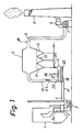
- Fig. 1 schematically shows a plant for cleaning flue gases from a coal-fired central heating plant 1, said flue gases containing dust, such as fly ash.
- a preheater 2 is arranged to transmit heat from the hot flue gases to combustion air, which is supplied through a duct 2a to the central heating plant 1 by means of a fan 3.
- the hot flue gases are passed through a duct 4 to a dust separator 5, which in the shown embodiment is a fabric filter, which in known manner comprises a plurality of rows of filter bags and through which the flue gases are passed to be cleaned.
- the thus cleaned flue gases are passed through a duct 6 to a flue gas blower 7, which through a duct 8 feeds them to a chimney 9 to be discharged into the atmosphere.
- the dust separator can also be, for instance, an electrostatic precipitator.
- the duct 4 comprises a vertical portion 10.
- a mixer 11 communicates with this portion 10 in the lower part thereof.
- the mixer 11 introduces in the manner that will be described in more detail below moistened and agglomerated dust particles into the flue gases in the lower part of the duct portion 10.
- the dust particles separated in the dust separator 5 are collected in the hoppers 12 of the dust separator 5. Part of the collected dust particles is recirculated in the system by being passed to the mixer 11 (arrow P1). The remainder of the collected dust particles is transported away in a manner not described in detail, for instance, by means of a screw conveyor.
- the mixer 11 is a mixer of the type described in WO 96/16727 and shown in more detail in Figs 2-4.
- the mixer 11 shown in Figs 2-4 comprises a container 13, which essentially is in the shape of an elongate, parallelepipedal box.
- the container 13 has two vertical side walls 14 and 15, a vertical rear end wall 16, a vertical front end wall 17, a horizontal upper bottom 18, a horizontal lower bottom 19 and a horizontal top or lid 20.
- the container 13 has an inlet 21, through which dust particles from the hoppers 12 are supplied from above into the container 13 (arrow P1 in Figs 1 and 2), and at its front end, an outlet 22, through which a homogeneous mixture of agglomerated dust particles and water is discharged (arrows P2 in Figs 3 and 4).
- the front end of the container 13 is inserted in the vertical duct portion 10, through which the flue gases are conducted upwards (arrows P3 in Figs 1, 2 and 4).
- the outlet 22 is an overflow formed as a result of the side walls 14 and 15 being lower in the part of the container 13 inserted in the duct portion 10 than in the container part located outside the duct portion 10.
- the top 20 extends from the inlet 21 to the outlet 22, i.e. up to the duct portion 10.
- the two bottoms 18 and 19 define a chamber 23 which, in the lateral direction, is delimited by the two side walls 14 and 15 and, in the longitudinal direction, is delimited by the two end walls 16 and 17.
- the ceiling of the chamber 23, i.e. the upper bottom 18, consists of an air-permeable fluidisation cloth of polyester mounted in stretched state in the container 13.
- An air-supply means, which in the embodiment shown consists of two air inlets 24 and 25, is arranged to supply air to the chamber 23 (arrows P4 in Figs 2 and 3), so as to fluidise the dust particles in the container 13.
- a water-supply line 26, which disposed above the container 13 is connected to a plurality of nozzles 27 arranged in the upper part of the container 13 to spray water in finely-divided form over the dust particles in the container.
- the nozzles 27, of which but a few are shown in the drawings, are arranged in two parallel rows extending along the container 13.
- Two juxtaposed horizontal shafts 28, 28' extend along the entire container 13 and are rotatably mounted in the two end walls 16 and 17 with the aid of bearings 29, 29' and 30, 30', respectively.
- a motor 31 is arranged to rotate the shafts 28, 28' via a transmission unit 32.
- Each shaft 28, 28' supports a plurality of elliptic discs 33, 33', which, about their minor axes, are mounted in inclined state on the shafts 28, 28' at an axial distance from one another.
- the shafts 28, 28' extend through the centres of the respective discs 33, 33'.
- each disc 33, 33' is so inclined in relation to the shaft 28, 28' that the angle ⁇ between the major axis of the disc and the shaft 28, 28' is about 60° (see Fig. 2). This angle ⁇ may vary between 45° and 80°.
- the discs 33, 33' are so inclined in relation to the respective shafts 28, 28' and have such an elliptic shape as to have a circular axial projection, as illustrated in Fig. 4.
- the discs 33, 33' are so positioned on the respective shafts 28, 28' that the discs of the one shaft project into the spaces between the discs of the other shaft.
- Each of the discs 33, 33' arranged and designed in the manner indicated above performs, during the rotation of the shafts 28, 28', a throwing movement conducive to thorough mixing of the dust particles.
- the chamber 23 is divided into a front part chamber 23a, which is situated in the duct portion 10, and a rear part chamber 23b.
- the air inlet 24 opens into the rear part chamber 23b, while the air inlet 25 opens into the front part chamber 23a.
- the dust particles are moistened with water which is supplied through the nozzles 27.
- the mixer 11 produces a homogeneously moistened, homogeneous mixture of dust particles which is, via the overflow 22 of the mixer 11, continuously introduced into the duct portion 10 as agglomerated dust particles.
- the flow rate of the flue gases was 45,000 Nm 3 /h.
- the flue gases had a dust content of 22.5 g/Nm 3 and a temperature of 130°C.
- the average particle size of the dust was 20 ⁇ m.
- the differential pressure over the fabric filter 5, which comprised 20 rows of filter bags, was constantly kept at 2,000 Pa by cleaning every row of filter bags by means of a strong compressed-air pulse, an entire cycle for cleaning all the rows of filter bags of the filter being passed in about 10 min. The interval between the pulses thus was about 30 s.
- the recirculation circuit comprising the mixer 11 was not used.
- the dust content of the flue gases at B in the duct 6 was measured to be 21.2 mg/Nm 3 .
- the flow rate of the flue gases was 45,000 Nm 3 /h.
- the flue gases had a dust content of 19.3 g/Nm 3 and a temperature of 130°C.
- the differential pressure over the fabric filter 5, which comprised 20 rows of filter bags, was constantly kept at 2,000 Pa by cleaning each row of filter bags by means of a strong compressed-air pulse, an entire cycle for cleaning all the rows of filter bags of the filter being passed in about 30 s. The interval between the pulses thus was about 1.5 s.
- separated dust particles were recirculated in an amount of about 60 t/h.
- the recirculated dust particles had an average particle size of 26 ⁇ m.
- the dust content of the flue gases at B in the duct 6 was measured to be 35 mg/Nm 3 .
- the flow rate of the flue gases was 45,000 Nm 3 /h.
- the flue gases had a dust content of 20.5 g/Nm 3 and a temperature of 130°C.
- the differential pressure over the fabric filter 5, which comprised 20 rows of filter bags, was constantly kept at 2,000 Pa by cleaning each row of filter bags by means of a strong compressed-air pulse, an entire cycle for cleaning all rows of filter bags of the filter being passed in about 16 min. The interval between the pulses thus was about 48 s.
- separated dust particles were recirculated in an amount of about 60 t/h.
- the recirculated dust particles had an average particle size of 33 ⁇ m.
- Water was supplied to the mixer 11 in an amount of about 1.3 m 3 /h, thereby cooling the flue gases to about 75°C.
- the dust content of the flue gases at B in the duct 6 was measured to be 15.1 mg/Nm 3 .
- the flow rate of the flue gases was 45,000 Nm 3 /h.
- the flue gases had a dust content of 20.2 g/Nm 3 and a temperature of 130°C.
- the differential pressure over the fabric filter 5, which comprised 20 rows of filter bags, was constantly kept at 2,000 Pa by cleaning each row of filter bags by means of a strong compressed-air pulse, an entire cycle for cleaning all rows of filter bags of the filter being passed in about 28 min. Thus, the interval between the pulses was about 84 s.
- separated dust particles were recirculated in an amount of about 60 t/h.
- the recirculated dust particles had an average particle size of 40 ⁇ m.
- Water was supplied to the mixer 11 in an amount of about 1.4 m 3 /h, thereby cooling the flue gases to about 70°C.
- the dust content of the flue gases at B in the duct 6 was measured to be 8.8 mg/Nm 3 .
- the flow rate of the flue gases was 45,000 Nm 3 /h.
- the flue gases had a dust content of 18.5 g/Nm 3 and a temperature of 130°C.
- the differential pressure over the fabric filter 5, which comprised 20 rows of filter bags, was constantly kept at 2,000 Pa by cleaning each row of filter bags by means of a strong compressed-air pulse, an entire cycle for cleaning all rows of filter bags of the filter being passed in about 62 min. Thus, the interval between the pulses was about 186 s.
- separated dust particles were recirculated in an amount of about 60 t/h.
- the recirculated dust particles had an average particle size of 36 ⁇ m. Water was supplied to the mixer 11 in an amount of about 1.5 m 3 /h, thereby cooling the flue gases to about 65°C.
- the dust content of the flue gases at B in the duct 6 was measured to be 1.7 mg/Nm 3 .
Landscapes
- Chemical & Material Sciences (AREA)
- Chemical Kinetics & Catalysis (AREA)
- Filtering Of Dispersed Particles In Gases (AREA)
- Separation Using Semi-Permeable Membranes (AREA)
- Treating Waste Gases (AREA)
- Cyclones (AREA)
Applications Claiming Priority (3)
| Application Number | Priority Date | Filing Date | Title |
|---|---|---|---|
| SE9504557A SE505579C2 (sv) | 1995-12-20 | 1995-12-20 | Sätt att avskilja stoft från varma processgaser |
| SE9504557 | 1995-12-20 | ||
| PCT/SE1996/001454 WO1997022400A1 (en) | 1995-12-20 | 1996-11-12 | Method for separating dust from hot process gases |
Publications (2)
| Publication Number | Publication Date |
|---|---|
| EP0876191A1 EP0876191A1 (en) | 1998-11-11 |
| EP0876191B1 true EP0876191B1 (en) | 2002-04-17 |
Family
ID=20400649
Family Applications (1)
| Application Number | Title | Priority Date | Filing Date |
|---|---|---|---|
| EP96938601A Expired - Lifetime EP0876191B1 (en) | 1995-12-20 | 1996-11-12 | Method for separating dust from hot process gases |
Country Status (11)
| Country | Link |
|---|---|
| US (1) | US6051054A (da) |
| EP (1) | EP0876191B1 (da) |
| AT (1) | ATE216279T1 (da) |
| AU (1) | AU7593896A (da) |
| DE (1) | DE69620795T2 (da) |
| DK (1) | DK0876191T3 (da) |
| ES (1) | ES2175144T3 (da) |
| SE (1) | SE505579C2 (da) |
| TR (1) | TR199601029A1 (da) |
| WO (1) | WO1997022400A1 (da) |
| ZA (1) | ZA9610152B (da) |
Families Citing this family (12)
| Publication number | Priority date | Publication date | Assignee | Title |
|---|---|---|---|---|
| SE512227C2 (sv) * | 1998-06-24 | 2000-02-14 | Flaekt Ab | Sätt att rena rökgaser under uppstart av en panna |
| USD489794S1 (en) | 2002-07-29 | 2004-05-11 | Media Blast & Abrasives, Inc. | Compressed air delivery manifold |
| USD476668S1 (en) | 2002-07-29 | 2003-07-01 | Media Blast & Abrasives, Inc. | Abrasive media delivery device |
| USD482828S1 (en) | 2002-07-29 | 2003-11-25 | Media Blast & Abrasives, Inc. | Abrasive media separator |
| USD482827S1 (en) | 2002-07-29 | 2003-11-25 | Media Blast & Abrasives, Inc. | Abrasive media dust collector |
| US20040106366A1 (en) * | 2002-08-26 | 2004-06-03 | Robinson Robert A. | Portable pipe restoration system |
| US20060037293A1 (en) * | 2004-08-17 | 2006-02-23 | Storer Ron D | Blast medium pot |
| US7008304B1 (en) * | 2004-08-17 | 2006-03-07 | Media Blast & Abrasives, Inc. | Abrasive and dust separator |
| US20070202781A1 (en) * | 2006-02-28 | 2007-08-30 | Media Blast & Abrasives, Inc. | Blast media nozzle and nozzle assembly |
| US7766997B2 (en) | 2007-12-21 | 2010-08-03 | Alstom Technology Ltd | Method of reducing an amount of mercury in a flue gas |
| US9623539B2 (en) | 2014-07-07 | 2017-04-18 | Media Blast & Abrasive, Inc. | Carving cabinet having protective carving barrier |
| US20190201828A1 (en) | 2017-12-29 | 2019-07-04 | Media Blast & Abrasive, Inc. | Adjustable abrasive & dust separator |
Family Cites Families (12)
| Publication number | Priority date | Publication date | Assignee | Title |
|---|---|---|---|---|
| DE2113062C3 (de) * | 1971-03-18 | 1975-12-04 | Heinrich Luehr Vdi Staubtechnik, 4960 Stadthagen | Verfahren zum Entstauben von Feinststaub enthaltenden Staubgasen mittels Taschen- oder Schlauchfiltern |
| GB1445810A (en) * | 1973-09-07 | 1976-08-11 | Berz W | Apparatus for separating dust from a dust-containing gas |
| US4205931A (en) * | 1978-12-04 | 1980-06-03 | Combustion Engineering, Inc. | Pneumatic ash transporting and containing system |
| US4378976A (en) * | 1981-08-14 | 1983-04-05 | Institute Of Gas Technology | Combined sonic agglomerator/cross flow filtration apparatus and process for solid particle and/or liquid droplet removal from gas streams |
| US4874402A (en) * | 1981-12-01 | 1989-10-17 | Shell Oil Company | Process for purifying and cooling a hot gas |
| US4579567A (en) * | 1984-09-18 | 1986-04-01 | Phillips Petroleum Company | Agglomerating carbon black using cyclone at entrance to bag filter |
| DE3639824A1 (de) * | 1986-10-22 | 1988-05-05 | Margraf Adolf | Filternder abscheider fuer partikel und schadgase aus rohgasen |
| US4865629A (en) * | 1988-07-05 | 1989-09-12 | Industrial Filter & Pump Mfg. Co. | Control of particle size distribution in gas filtration |
| DE3925818A1 (de) * | 1989-08-04 | 1991-02-07 | Intensiv Filter Gmbh | Verfahren und vorrichtung zum entstauben von zinkbaedern |
| DE19515352A1 (de) * | 1994-05-04 | 1995-11-09 | Volkswagen Ag | Vorrichtung zum Abscheiden von Partikeln aus einem Abgasstrom |
| US5505766A (en) * | 1994-07-12 | 1996-04-09 | Electric Power Research, Inc. | Method for removing pollutants from a combustor flue gas and system for same |
| TW279242B (en) * | 1994-11-29 | 1996-06-21 | Asahi Denka Kogyo Kk | The wasted-gas processing method & device for CVD apparatus |
-
1995
- 1995-12-20 SE SE9504557A patent/SE505579C2/sv not_active IP Right Cessation
-
1996
- 1996-11-12 AT AT96938601T patent/ATE216279T1/de active
- 1996-11-12 WO PCT/SE1996/001454 patent/WO1997022400A1/en not_active Ceased
- 1996-11-12 ES ES96938601T patent/ES2175144T3/es not_active Expired - Lifetime
- 1996-11-12 DE DE69620795T patent/DE69620795T2/de not_active Expired - Lifetime
- 1996-11-12 AU AU75938/96A patent/AU7593896A/en not_active Abandoned
- 1996-11-12 EP EP96938601A patent/EP0876191B1/en not_active Expired - Lifetime
- 1996-11-12 DK DK96938601T patent/DK0876191T3/da active
- 1996-12-03 ZA ZA9610152A patent/ZA9610152B/xx unknown
- 1996-12-19 TR TR96/01029A patent/TR199601029A1/xx unknown
-
1998
- 1998-06-19 US US09/100,099 patent/US6051054A/en not_active Expired - Lifetime
Also Published As
| Publication number | Publication date |
|---|---|
| EP0876191A1 (en) | 1998-11-11 |
| DE69620795D1 (de) | 2002-05-23 |
| SE9504557D0 (sv) | 1995-12-20 |
| ES2175144T3 (es) | 2002-11-16 |
| US6051054A (en) | 2000-04-18 |
| DK0876191T3 (da) | 2002-07-01 |
| SE9504557L (sv) | 1997-06-21 |
| TR199601029A1 (tr) | 1997-07-21 |
| ZA9610152B (en) | 1997-06-18 |
| WO1997022400A1 (en) | 1997-06-26 |
| DE69620795T2 (de) | 2002-10-17 |
| ATE216279T1 (de) | 2002-05-15 |
| SE505579C2 (sv) | 1997-09-15 |
| AU7593896A (en) | 1997-07-14 |
Similar Documents
| Publication | Publication Date | Title |
|---|---|---|
| EP0794830B1 (en) | Device for mixing particulate material and liquid | |
| EP0876191B1 (en) | Method for separating dust from hot process gases | |
| CN1080137C (zh) | 从热工艺气体中分离气体污染物的方法 | |
| CN1089268C (zh) | 用于混合颗粒材料和液体的装置 | |
| US4324770A (en) | Process for dry scrubbing of flue gas | |
| US4446109A (en) | System for dry scrubbing of flue gas | |
| US20130294992A1 (en) | Dry scrubber system | |
| SI9720030A (sl) | Naprava za dovajanje in razdelitev absorbirnega materiala v vod zgorelih plinov | |
| US4578876A (en) | Process and apparatus for spraying a powder with liquid | |
| US4622008A (en) | Method of and apparatus for the thermal regeneration of adsorbents | |
| EP0122112A2 (en) | Improvements in or relating to a process and apparatus for spraying a powder with liquid | |
| US5167931A (en) | SO2 control using moving granular beds | |
| US5266288A (en) | SO2 control using moving granular beds | |
| JPS61133122A (ja) | 煙道ガスや排ガス中の有害物質の中性化と分離のための方法と装置 | |
| EP0095459A4 (en) | METHOD AND SYSTEM FOR DRY PURIFICATION OF SMOKE GAS. | |
| AU545580B2 (en) | Process and system for dry scrubbing of flue gas | |
| SU889756A1 (ru) | Аэродинамический отделитель дл волокнистого материала | |
| CA2205995C (en) | Method for separating gaseous pollutants from hot process gases | |
| SU1207524A1 (ru) | Устройство дл обеспыливани зернистых материалов | |
| JP2002286364A (ja) | 粉粒体乾燥装置 |
Legal Events
| Date | Code | Title | Description |
|---|---|---|---|
| PUAI | Public reference made under article 153(3) epc to a published international application that has entered the european phase |
Free format text: ORIGINAL CODE: 0009012 |
|
| 17P | Request for examination filed |
Effective date: 19980603 |
|
| AK | Designated contracting states |
Kind code of ref document: A1 Designated state(s): AT BE CH DE DK ES FI FR GB GR IE IT LI LU MC NL PT SE |
|
| GRAG | Despatch of communication of intention to grant |
Free format text: ORIGINAL CODE: EPIDOS AGRA |
|
| 17Q | First examination report despatched |
Effective date: 20010702 |
|
| GRAG | Despatch of communication of intention to grant |
Free format text: ORIGINAL CODE: EPIDOS AGRA |
|
| GRAH | Despatch of communication of intention to grant a patent |
Free format text: ORIGINAL CODE: EPIDOS IGRA |
|
| REG | Reference to a national code |
Ref country code: GB Ref legal event code: IF02 |
|
| GRAH | Despatch of communication of intention to grant a patent |
Free format text: ORIGINAL CODE: EPIDOS IGRA |
|
| GRAA | (expected) grant |
Free format text: ORIGINAL CODE: 0009210 |
|
| RAP1 | Party data changed (applicant data changed or rights of an application transferred) |
Owner name: ALSTOM POWER SWEDEN HOLDING AB |
|
| AK | Designated contracting states |
Kind code of ref document: B1 Designated state(s): AT BE CH DE DK ES FI FR GB GR IE IT LI LU MC NL PT SE |
|
| PG25 | Lapsed in a contracting state [announced via postgrant information from national office to epo] |
Ref country code: NL Free format text: LAPSE BECAUSE OF FAILURE TO SUBMIT A TRANSLATION OF THE DESCRIPTION OR TO PAY THE FEE WITHIN THE PRESCRIBED TIME-LIMIT Effective date: 20020417 Ref country code: LI Free format text: LAPSE BECAUSE OF FAILURE TO SUBMIT A TRANSLATION OF THE DESCRIPTION OR TO PAY THE FEE WITHIN THE PRESCRIBED TIME-LIMIT Effective date: 20020417 Ref country code: IT Free format text: LAPSE BECAUSE OF FAILURE TO SUBMIT A TRANSLATION OF THE DESCRIPTION OR TO PAY THE FEE WITHIN THE PRESCRIBED TIME-LIMIT;WARNING: LAPSES OF ITALIAN PATENTS WITH EFFECTIVE DATE BEFORE 2007 MAY HAVE OCCURRED AT ANY TIME BEFORE 2007. THE CORRECT EFFECTIVE DATE MAY BE DIFFERENT FROM THE ONE RECORDED. Effective date: 20020417 Ref country code: GR Free format text: LAPSE BECAUSE OF FAILURE TO SUBMIT A TRANSLATION OF THE DESCRIPTION OR TO PAY THE FEE WITHIN THE PRESCRIBED TIME-LIMIT Effective date: 20020417 Ref country code: CH Free format text: LAPSE BECAUSE OF FAILURE TO SUBMIT A TRANSLATION OF THE DESCRIPTION OR TO PAY THE FEE WITHIN THE PRESCRIBED TIME-LIMIT Effective date: 20020417 Ref country code: BE Free format text: LAPSE BECAUSE OF FAILURE TO SUBMIT A TRANSLATION OF THE DESCRIPTION OR TO PAY THE FEE WITHIN THE PRESCRIBED TIME-LIMIT Effective date: 20020417 Ref country code: AT Free format text: LAPSE BECAUSE OF FAILURE TO SUBMIT A TRANSLATION OF THE DESCRIPTION OR TO PAY THE FEE WITHIN THE PRESCRIBED TIME-LIMIT Effective date: 20020417 |
|
| REF | Corresponds to: |
Ref document number: 216279 Country of ref document: AT Date of ref document: 20020515 Kind code of ref document: T |
|
| REG | Reference to a national code |
Ref country code: CH Ref legal event code: EP |
|
| REG | Reference to a national code |
Ref country code: IE Ref legal event code: FG4D |
|
| REF | Corresponds to: |
Ref document number: 69620795 Country of ref document: DE Date of ref document: 20020523 |
|
| REG | Reference to a national code |
Ref country code: DK Ref legal event code: T3 |
|
| PG25 | Lapsed in a contracting state [announced via postgrant information from national office to epo] |
Ref country code: SE Free format text: LAPSE BECAUSE OF FAILURE TO SUBMIT A TRANSLATION OF THE DESCRIPTION OR TO PAY THE FEE WITHIN THE PRESCRIBED TIME-LIMIT Effective date: 20020717 Ref country code: PT Free format text: LAPSE BECAUSE OF FAILURE TO SUBMIT A TRANSLATION OF THE DESCRIPTION OR TO PAY THE FEE WITHIN THE PRESCRIBED TIME-LIMIT Effective date: 20020717 |
|
| NLV1 | Nl: lapsed or annulled due to failure to fulfill the requirements of art. 29p and 29m of the patents act | ||
| ET | Fr: translation filed | ||
| REG | Reference to a national code |
Ref country code: CH Ref legal event code: PL |
|
| PG25 | Lapsed in a contracting state [announced via postgrant information from national office to epo] |
Ref country code: LU Free format text: LAPSE BECAUSE OF NON-PAYMENT OF DUE FEES Effective date: 20021112 Ref country code: IE Free format text: LAPSE BECAUSE OF NON-PAYMENT OF DUE FEES Effective date: 20021112 |
|
| REG | Reference to a national code |
Ref country code: ES Ref legal event code: FG2A Ref document number: 2175144 Country of ref document: ES Kind code of ref document: T3 |
|
| PLBE | No opposition filed within time limit |
Free format text: ORIGINAL CODE: 0009261 |
|
| STAA | Information on the status of an ep patent application or granted ep patent |
Free format text: STATUS: NO OPPOSITION FILED WITHIN TIME LIMIT |
|
| 26N | No opposition filed |
Effective date: 20030120 |
|
| PG25 | Lapsed in a contracting state [announced via postgrant information from national office to epo] |
Ref country code: MC Free format text: LAPSE BECAUSE OF NON-PAYMENT OF DUE FEES Effective date: 20030601 |
|
| REG | Reference to a national code |
Ref country code: IE Ref legal event code: MM4A |
|
| REG | Reference to a national code |
Ref country code: ES Ref legal event code: PC2A |
|
| REG | Reference to a national code |
Ref country code: FR Ref legal event code: CD |
|
| REG | Reference to a national code |
Ref country code: ES Ref legal event code: PC2A Owner name: ALSTOM TECHNOLOGY LTD. Effective date: 20130228 |
|
| REG | Reference to a national code |
Ref country code: FR Ref legal event code: TP Owner name: ALSTOM TECHNOLOGY LTD., CH Effective date: 20130213 |
|
| REG | Reference to a national code |
Ref country code: DE Ref legal event code: R082 Ref document number: 69620795 Country of ref document: DE Representative=s name: RUEGER, BARTHELT & ABEL, DE Effective date: 20130225 Ref country code: DE Ref legal event code: R082 Ref document number: 69620795 Country of ref document: DE Representative=s name: ROESLER PATENTANWALTSKANZLEI, DE Effective date: 20130225 Ref country code: DE Ref legal event code: R081 Ref document number: 69620795 Country of ref document: DE Owner name: GENERAL ELECTRIC TECHNOLOGY GMBH, CH Free format text: FORMER OWNER: ALSTOM SWEDEN AB, NORRKOEPING, SE Effective date: 20130225 Ref country code: DE Ref legal event code: R081 Ref document number: 69620795 Country of ref document: DE Owner name: ALSTOM TECHNOLOGY LTD., CH Free format text: FORMER OWNER: ALSTOM SWEDEN AB, NORRKOEPING, SE Effective date: 20130225 |
|
| REG | Reference to a national code |
Ref country code: GB Ref legal event code: 732E Free format text: REGISTERED BETWEEN 20130418 AND 20130424 |
|
| REG | Reference to a national code |
Ref country code: FR Ref legal event code: PLFP Year of fee payment: 20 |
|
| PGFP | Annual fee paid to national office [announced via postgrant information from national office to epo] |
Ref country code: DE Payment date: 20151119 Year of fee payment: 20 Ref country code: DK Payment date: 20151118 Year of fee payment: 20 Ref country code: FI Payment date: 20151111 Year of fee payment: 20 Ref country code: GB Payment date: 20151118 Year of fee payment: 20 |
|
| PGFP | Annual fee paid to national office [announced via postgrant information from national office to epo] |
Ref country code: FR Payment date: 20151119 Year of fee payment: 20 Ref country code: ES Payment date: 20151111 Year of fee payment: 20 |
|
| REG | Reference to a national code |
Ref country code: DE Ref legal event code: R082 Ref document number: 69620795 Country of ref document: DE Representative=s name: RUEGER ABEL PATENTANWAELTE PARTGMBB, DE Ref country code: DE Ref legal event code: R082 Ref document number: 69620795 Country of ref document: DE Representative=s name: RUEGER ABEL PATENT- UND RECHTSANWAELTE, DE Ref country code: DE Ref legal event code: R082 Ref document number: 69620795 Country of ref document: DE Representative=s name: RUEGER, BARTHELT & ABEL, DE |
|
| REG | Reference to a national code |
Ref country code: DE Ref legal event code: R082 Ref document number: 69620795 Country of ref document: DE Representative=s name: RUEGER ABEL PATENT- UND RECHTSANWAELTE, DE Ref country code: DE Ref legal event code: R082 Ref document number: 69620795 Country of ref document: DE Representative=s name: RUEGER, BARTHELT & ABEL, DE Ref country code: DE Ref legal event code: R081 Ref document number: 69620795 Country of ref document: DE Owner name: GENERAL ELECTRIC TECHNOLOGY GMBH, CH Free format text: FORMER OWNER: ALSTOM TECHNOLOGY LTD., BADEN, CH |
|
| REG | Reference to a national code |
Ref country code: DE Ref legal event code: R071 Ref document number: 69620795 Country of ref document: DE |
|
| REG | Reference to a national code |
Ref country code: DK Ref legal event code: EUP Effective date: 20161112 |
|
| REG | Reference to a national code |
Ref country code: GB Ref legal event code: PE20 Expiry date: 20161111 |
|
| REG | Reference to a national code |
Ref country code: FR Ref legal event code: CD Owner name: ALSTOM TECHNOLOGY LTD, CH Effective date: 20161124 |
|
| PG25 | Lapsed in a contracting state [announced via postgrant information from national office to epo] |
Ref country code: GB Free format text: LAPSE BECAUSE OF EXPIRATION OF PROTECTION Effective date: 20161111 |
|
| REG | Reference to a national code |
Ref country code: ES Ref legal event code: FD2A Effective date: 20170224 |
|
| PG25 | Lapsed in a contracting state [announced via postgrant information from national office to epo] |
Ref country code: ES Free format text: LAPSE BECAUSE OF EXPIRATION OF PROTECTION Effective date: 20161113 |