EP0876013A1 - Procédé et dispositif de fonctionnement sans interruption de liaisons de communication entre satellites dans des réseaux LEO - Google Patents
Procédé et dispositif de fonctionnement sans interruption de liaisons de communication entre satellites dans des réseaux LEO Download PDFInfo
- Publication number
- EP0876013A1 EP0876013A1 EP97122928A EP97122928A EP0876013A1 EP 0876013 A1 EP0876013 A1 EP 0876013A1 EP 97122928 A EP97122928 A EP 97122928A EP 97122928 A EP97122928 A EP 97122928A EP 0876013 A1 EP0876013 A1 EP 0876013A1
- Authority
- EP
- European Patent Office
- Prior art keywords
- terminals
- optical
- satellites
- satellite
- azimuth
- Prior art date
- Legal status (The legal status is an assumption and is not a legal conclusion. Google has not performed a legal analysis and makes no representation as to the accuracy of the status listed.)
- Granted
Links
Images


Classifications
-
- H—ELECTRICITY
- H04—ELECTRIC COMMUNICATION TECHNIQUE
- H04B—TRANSMISSION
- H04B10/00—Transmission systems employing electromagnetic waves other than radio-waves, e.g. infrared, visible or ultraviolet light, or employing corpuscular radiation, e.g. quantum communication
- H04B10/11—Arrangements specific to free-space transmission, i.e. transmission through air or vacuum
- H04B10/118—Arrangements specific to free-space transmission, i.e. transmission through air or vacuum specially adapted for satellite communication
-
- H—ELECTRICITY
- H04—ELECTRIC COMMUNICATION TECHNIQUE
- H04B—TRANSMISSION
- H04B7/00—Radio transmission systems, i.e. using radiation field
- H04B7/14—Relay systems
- H04B7/15—Active relay systems
- H04B7/185—Space-based or airborne stations; Stations for satellite systems
- H04B7/18521—Systems of inter linked satellites, i.e. inter satellite service
Definitions
- the invention relates to a method and an arrangement for the uninterrupted operation of optical communication links between satellites in LEO networks ( L ow E arth O rbiting).
- a single fixed radio station of such a network can detect mobile subscribers up to a distance of approximately 20 km, the maximum extent of a cell thereby limited being considerably smaller in unfavorable terrain. Due to the positive experience with radio satellites in geostationary orbits, the idea suggests that the resulting independence from the terrain as well as the large spatial extent of the recorded area can be achieved with similar means for mobile radio systems.
- a feature of all the systems mentioned is the use of a large number of ones in low orbit satellites moving around the earth, which are divided into sub-groups distribute evenly on a Umlaubahn, which is characterized by the fact that it the plane containing the earth's equator passes through in two points at an obtuse angle.
- the Orbits of all satellites are arranged to each other in such a way that a uniform Coverage of the earth's surface is achieved by satellites.
- the ones described by the satellites Orbits overlap in two points depending on the inclination.
- inter-plane phasing and the choice a collision of satellites from angles of inclination of the individual orbit planes not equal to 90 ° avoided with different orbits.
- connection between the individual satellites is currently taking place via appropriately aligned microwave directional antennas. This is not a problem between satellites in the same orbit because of the distance and the direction of neighboring satellites are relatively stable. More complicated however, the situation with connections to the satellites of neighboring orbits. During an orbit around the earth, the intersection of all orbits occurs a change of sides of the satellites flying in the neighboring orbits.
- This method can be used advantageously in free-space optical transmission systems for uninterrupted connections between individual satellites globally accessible low earth orbiting satellite communication systems are used, by means of a device of small spatial dimension and low weight.
- Satellite transmission facilities through optical communication terminals. These are installed on every satellite in at least fourfold versions and contain a transmission device intended for transmission and reception, which means of an optical head is rotatable in azimuth and elevation.
- Terminals are on the outside of the satellite in the direction of movement and opposite attached to the direction of movement of the satellite so that the azimuthal Zero alignment of your telescopes with the tangent of the orbit described by the satellite coincides.
- Further configurations can include any number of terminals, in particular for the simultaneous maintenance of more than two connections to neighboring satellites.
- the homodyne method is provided for the data exchange between two satellites which is unaffected by extraneous light sources. In this way, the signal from a satellite directly in front of the sun can also be detected.
- the contact made with an optical terminal to a lateral satellite in another orbit is held during the crossing of the intersections of all orbits by tracking the very small and light telescope, which can be rotated about two axes. The tracking also takes place by means of coherently detected difference signals, so it is insensitive to disturbances caused by the sun.
- the optical power of the light beam emitted by an optical terminal is concentrated in a very narrow angular range, as a result of which the required transmission power is very low.
- the very precise alignment of the light beam on the desired satellite required as a critical factor also includes the advantage of interference-free communication with satellites arranged at a short mutual distance, as is the case in the area of overlapping orbits.
- Another advantage lies in the extremely high bandwidths that can be made available by optical communication. For example, at a wavelength of 1500 nm, a spectral segment of 1 nm width in the frequency range represents a bandwidth of approximately 130 GHz.
- Wired optical transmission systems which are exposed to the adversity of the transmission medium, in particular the dispersion of the group delay, enable the transmission of several hundred Gbit per second.
- bandwidth in the microwave spectrum can be released for the communication between earth and satellite, whereby the resulting increase in the data flow between the satellites can be easily managed by optical systems.
- Fig. 1 the 66 satellites 2 of the IRIDIUM network are shown schematically in their orbits around the earth.
- the central element of this group is a satellite 4 , which is connected to the satellites 12 and 8 that are traveling in and out of its own orbit 18 .
- Two further satellites 10 and 6 located on adjacent orbits 20 and 16 form routes with the satellite 4 , which form an angle of approximately 300 degrees and approximately 120 degrees with the tangent to the orbit of the satellite 4 .
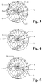
- FIGS. 4 and 5 show two further phases in the region of the orbits overlapping in the vicinity of the north pole, while the same situation is shown in the vicinity of the south pole in FIGS. 6 to 8 .
- FIGS. 6 to 8 show the ensemble of satellites known from FIGS. 2 to 5 before, during and after passing through the central satellite 4 the crossing point of the orbits located near the south pole.
- a curve shown in FIG. 9 shows, in the perspective of satellite 4, the azimuth and elevation detection angle of a satellite 6 or 10 flying in an adjacent orbit, which passes through the crossing points of all orbits in front of satellite 4 , during a full earth orbit.
- the elevation detection angle along curve 26 changes by less than twice its minimum value, so the mutual distance between satellites 6 or 10 and 4 is also large enough when flying through the crossing point of the orbits so that the angle between the satellites does not change too abruptly 6 or 10 and 4 existing routes to effect.
- the optical communication terminals required for optical connections can be attached to the satellites in the manner shown in FIG . While an optical terminal 32 maintains the connection to the satellite 12 flying in the same orbit, the satellite 8 flying in the same orbit is detected by a further optical terminal 36 .
- the two further optical terminals 34 and 38 detect the area on the left or right side in the direction of flight of the satellite and thus the closest satellites 6 and 10 that fly along in the adjacent orbits. As can be seen from the illustration, both optical terminals 34 and 38 can cover an angular range of -90 to +90 degrees in azimuth and thus detect both satellites flying on orbits that are adjacent on the right.
- a front or rear view ( FIG. 11 ) of the arrangement of the optical terminals shows an optical terminal 28 for maintaining the connection to a satellite flying ahead or in the same orbit and an optical terminal 30 , the connecting path of which emanates from this to one optional satellite on the right or left side is shown in the form of two lines.
- FIG. 12 shows the fully installed satellite network TELEDESIC with 840 satellites 40 .
- a selected interlinked group of TELEDESIC satellites is shown in FIG. 13 .
- the depth of the networking of individual groups is greater than with IRIDIUM, there are two satellites 52 and 54 or 56 and 58 flying in front or behind on the same orbit as well as satellites 44 and 46 and 50 lying in orbits adjacent to the left or right and 48 connected to a central satellite 42 of the group.
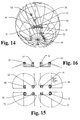
- FIG. 14 shows the group of satellites from FIG. 13 before it passes the intersection point of all orbits in the vicinity of the south pole, in which satellite 54 is located.
- optical terminals 74 and 82 hold the connections to the two satellites 52 and 54 flying in the same orbit, further optical terminals 72 and 76 are directed to the two satellites 56 and 58 flying in the same orbit. Further optical terminals 78 and 80 or 68 and 70 keep the connection to satellites moving on two nearest left or right sides of the orbits of the central satellite 42 . As can be seen from the front or rear view ( FIG.
- optical terminals 60 and 66 provided for connection to satellites flying in lateral orbits detect, in addition to those for satellites flying in or out of their own orbit attached optical terminals 62 and 64 are grouped on both sides due to the required elevation detection angle and their mutual distance on the satellite body. This also makes it possible to track satellites that fly to the side during an orbit around the world without any time gaps.
- Fig. 17 shows the azimuth and elevation detection angles at which a central satellite sees its neighbors in the orbit immediately adjacent. 17 therefore shows the azimuth or elevation detection angle which the connection path to satellites 44 and 50 in the next adjacent orbits describes during a full orbit of the group, provided that satellites 44 and 50 fly through the crossing points of the orbits beforehand.
- the curve 84 shows an elevation detection angle of approximately 1 degree, which suggests a short distance of the satellites given the high curvature of orbits close to the earth.
- Azimuth detection angles of around 90 degrees when the group flies over low latitudes of the earth indicate a very rapid change in the direction of the satellite that flies on the right or left side, which can still be managed with a small and light optical terminal.
- FIG. 18 shows the azimuth and elevation detection angles at which a central satellite sees its neighbors in the next-but-one right orbit.
- An analog curve 86 is therefore shown in this figure for the next-but-one networked satellites 46 and 48 on adjacent orbits.
- the small size of the optical terminals 60 and 66, together with their offset arrangement according to FIG. 16 ensures the seamless tracking of satellites traveling along the side over a full earth orbit of the entire group without mutual shadowing.
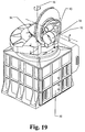
- FIG. 19 The structure of an optical terminal is shown in Fig. 19 .
- a housing 88 contains , in addition to parts of the electronics required for control and signal processing, essential parts of the optical system as described in detail in Swiss Patent Application 0548/97 .
- it also accommodates an essential part of the telescope, the orientation of which can be controlled by means of a rotating deflecting mirror.
- An alignable opening 98 of the telescope can be adjusted in its elevation by means of a mirror 90 rotatable about an elevation axis 92 and a mirror 94 rotatable about an azimuth axis 96 in the azimuth angle.
- the further embodiment of an optical terminal shown in FIG. 20 has a structure similar to the embodiment shown in FIG. 19 .
- An adjustable opening 104 of a telescope is attached to a mirror rotatable about an elevation axis, similar to FIG. 19, and is connected to a body 102 which rotates about an azimuth detection angle axis and which rests on a housing 100 .
- FIG. 10 shows that the axis of the opening 98 ( FIG. 19 ) of the eccentrically mounted telescope of an optical terminal 32 ( FIG. 10 ) runs parallel to the corresponding axis of the terminal 36 , but is directed in the other direction; the position of these axes therefore corresponds to an azimuth of 0 ° or 180 °.
- the terminals 34 and 38 which in reality each have only one telescope, are shown in FIG. 10 with the telescope in three positions each, in order to illustrate a movement of the axis which corresponds to an angle change from 0 ° to 180 °.
- the terminals 32 , 34 , 36 and 38 ( FIG.
- At least four miniaturized optical terminals can be arranged geometrically on the satellite body in such a way that their azimuth axes intersect a plane perpendicular to the direction of flight normal in four points, which a square, i.e. a rectangle or in generally an irregular square, form that the initial orientations of these four optical terminals are oriented parallel to the flight direction tangent, and that the initial orientations of two of these four optical terminals are directed with or against the satellite flight direction tangent.
- FIG. 10 can according to FIG. 21 with two additional terminals 106 may be equipped 108, the azimuth axes 33 and 39 and the azimuth axes of the terminals are located in a central plane between the by the azimuthal axes of the terminals 35 and 37 planes formed, and wherein these two additional azimuth axes intersect the reference plane in two points that are within the area of the quadrangle defined by the other four points.
- the head of the additional terminal protrudes above the height or depth of the other two heads 33 , 35 , these terminals need not be of the eccentric type.
- the terminals 108 and 37 , 39 (FIG. 22), which means that all terminals can also be of the symmetrical type.
- FIG. 15 shows that the axis of the opening 88 ( FIG. 18 ) of the eccentrically mounted telescope of an optical terminal 74 coincides with the corresponding axis of the terminal 72 , but is directed in the other direction; the position of these axes therefore corresponds to an azimuth of 0 °.
- the terminals 68 and 70 which in reality each have only one telescope, are shown in FIG. 15 with the telescope in three positions in each case in order to illustrate a movement of the axis which corresponds to an angle change from 0 ° to 180 °. 15, the four further terminals 76 , 78 , 80 and 82 are arranged symmetrically with respect to the terminals 72 , 70 , 68 and 74 , respectively.
- the terminals 68 , 70 , 72 , 74 , 76 , 78 , 80 and 82 are mounted in a satellite, possibly via a carrier, as indicated for example in FIG. 22 with the reference symbol 110 , in such a way that their azimuth axes form eight parallel straight lines, four of which are each in one plane and intersect a plane perpendicular to them in eight points, which form a rectangle.
- the limit of the elevation at terminals 68 , 70 , 78 and 80 can reach an angle of, for example, ⁇ 7.7 ° and at terminals 72 , 74 , 76 and 82 an angle of, for example, ⁇ 4.5 or ⁇ 9 ° .
- the telescopic heads are offset such that a change in the respective azimuth detection angle Wa in the range from 0 ° to 160 ° is readily possible.
- the lead angles of the transmission beams of the optical terminals that are necessary due to relative movements of the satellites 4 - 12 and 42 - 58 can be set by means of the expected relative movements of the satellites 4 - 12 and 42 - 58 involved , which are calculated in a computer from the orbital data of the satellites 4 involved - 12 and 42 - 58 can be determined.
- the openings 88 and 104 of the telescope used on the transmitting and receiving sides can be aligned in elevation and azimuth by means of the mirrors 90 and 94 , as a result of which only small masses have to be moved to align the telescope.
- the terminals can also be of the eccentric type, such that the openings 98 and 104 of the telescope used on the transmitting and receiving sides are attached to the side of the body 102 which can be rotated about the azimuth axis, as a result of which radiation can be radiated past bodies which are arranged adjacent to the satellite, or whereby individual terminals can be arranged offset accordingly.
- the designations Ir 504, Ir 505 and Ir 506 apply to satellites 8, 4 and 12 in the example according to FIG. 2
- the designations Ir 406 and Ir 604 apply to satellites 10 and 6 .
Applications Claiming Priority (3)
| Application Number | Priority Date | Filing Date | Title |
|---|---|---|---|
| CH1153/97 | 1997-05-16 | ||
| CH115397 | 1997-05-16 | ||
| CH115397 | 1997-05-16 |
Publications (2)
| Publication Number | Publication Date |
|---|---|
| EP0876013A1 true EP0876013A1 (fr) | 1998-11-04 |
| EP0876013B1 EP0876013B1 (fr) | 1999-11-03 |
Family
ID=4203726
Family Applications (1)
| Application Number | Title | Priority Date | Filing Date |
|---|---|---|---|
| EP97122928A Expired - Lifetime EP0876013B1 (fr) | 1997-05-16 | 1997-12-29 | Procédé et dispositif de fonctionnement sans interruption de liaisons de communication entre satallites dans des réseaux LEO |
Country Status (5)
| Country | Link |
|---|---|
| US (1) | US6246501B1 (fr) |
| EP (1) | EP0876013B1 (fr) |
| JP (1) | JPH10336111A (fr) |
| CA (1) | CA2210486A1 (fr) |
| DE (1) | DE59700656D1 (fr) |
Cited By (8)
| Publication number | Priority date | Publication date | Assignee | Title |
|---|---|---|---|---|
| WO2000030415A1 (fr) * | 1998-11-13 | 2000-05-25 | Talking Lights, Llc. | Systeme de communication |
| US6327065B1 (en) | 2000-01-13 | 2001-12-04 | Trw Inc. | Fine pointing assembly configuration |
| US6469815B1 (en) | 1999-04-28 | 2002-10-22 | Trw Inc. | Inter-satellite optical link acquisition sensor |
| US6522440B1 (en) | 1999-04-28 | 2003-02-18 | Trw Inc. | Inter-satellite optical link track sensor |
| US6535314B1 (en) | 2000-01-13 | 2003-03-18 | Trw Inc. | Satellite optical communication beam acquisition techniques |
| US6590685B1 (en) | 2000-01-13 | 2003-07-08 | Northrop Grumman Corporation | Satellite communication optical beam acquisition techniques using a plurality of scan patterns |
| US6957020B2 (en) | 1999-07-07 | 2005-10-18 | Northrop Grumman Corporation | Optical inter-satellite link (OISL) gimbal |
| WO2019011919A1 (fr) * | 2017-07-14 | 2019-01-17 | Deutsches Zentrum Für Luft- Und Raumfahrt | Satellite de navigation, notamment pour une orbite terrestre moyenne |
Families Citing this family (9)
| Publication number | Priority date | Publication date | Assignee | Title |
|---|---|---|---|---|
| US20040001720A1 (en) * | 2002-06-27 | 2004-01-01 | Krill Jerry A. | Satellite-based mobile communication system |
| US7379088B2 (en) * | 2002-07-01 | 2008-05-27 | The Johns Hopkins University | System and method for real-time image control and processing for use in wide area space based surveillance |
| JP5994773B2 (ja) * | 2011-03-25 | 2016-09-21 | 日本電気株式会社 | 送信器、受信器、送信方法、受信方法及び通信システム |
| US9065564B2 (en) * | 2011-10-03 | 2015-06-23 | Kara Whitney Johnson | World-wide, wide-band, low-latency, mobile internet and system therefor |
| US8913894B2 (en) * | 2012-07-13 | 2014-12-16 | Raytheon Company | High-bandwidth optical communications relay architecture |
| US9729234B2 (en) * | 2015-06-22 | 2017-08-08 | The Boeing Company | Free space optical communications network with bent pipe channel and pilot channel |
| FR3051088B1 (fr) * | 2016-05-04 | 2018-05-25 | Thales | Dispositif de communication inter-satellites, satellite et constellation de satellites |
| GB2583074A (en) * | 2019-04-02 | 2020-10-21 | Stratospheric Platforms Ltd | Hybrid communication |
| WO2022137344A1 (fr) * | 2020-12-22 | 2022-06-30 | 三菱電機株式会社 | Système de satellite de communication, installation de commande côté terre, installation de mise à la terre, satellite artificiel, centre de mise à la terre de communication, et dispositif de recherche d'itinéraire de transmission |
Family Cites Families (7)
| Publication number | Priority date | Publication date | Assignee | Title |
|---|---|---|---|---|
| EP0287032B1 (fr) * | 1987-04-13 | 1996-02-28 | Nec Corporation | Système d'alignement optique |
| US5184241A (en) * | 1989-06-21 | 1993-02-02 | The United States Of America As Represented By The Administrator Of The National Aeronautics & Space Admininstration | Doppler shift compensation system for laser transmitters and receivers |
| US5218467A (en) * | 1990-12-28 | 1993-06-08 | Nasa And Laser Data Technology, Inc. | Multi-access laser communications transceiver system |
| US5710652A (en) * | 1992-08-27 | 1998-01-20 | Trex Communications | Laser communication transceiver and system |
| US5592320A (en) * | 1994-08-15 | 1997-01-07 | Hughes Aircraft Company | Satellite communications system |
| US5659413A (en) * | 1995-02-28 | 1997-08-19 | The Mitre Corporation | Laser satellite communication system |
| US5890679A (en) * | 1996-09-26 | 1999-04-06 | Loral Aerospace Corp. | Medium earth orbit communication satellite system |
-
1997
- 1997-06-25 US US08/882,268 patent/US6246501B1/en not_active Expired - Fee Related
- 1997-07-23 CA CA002210486A patent/CA2210486A1/fr not_active Abandoned
- 1997-08-11 JP JP9216273A patent/JPH10336111A/ja active Pending
- 1997-12-29 DE DE59700656T patent/DE59700656D1/de not_active Expired - Lifetime
- 1997-12-29 EP EP97122928A patent/EP0876013B1/fr not_active Expired - Lifetime
Non-Patent Citations (4)
| Title |
|---|
| GIGGENBACH D: "OPTISCHE KOMUNIKATION IM WELTRAUM", FUNKSCHAU, vol. 68, no. 2, 5 January 1996 (1996-01-05), pages 68 - 70, XP000554686 * |
| KATSUTOSHI TSUKAMOTO ET AL: "HETERODYNE OPTICAL DETECTION/SPATIAL TRACKING SYSTEM USING SPATIAL FIELD PATTERN MATCHING BETWEEN SIGNAL AND LOCAL LIGHTS", ELECTRONICS & COMMUNICATIONS IN JAPAN, PART I - COMMUNICATIONS, vol. 77, no. 12, 1 December 1994 (1994-12-01), pages 73 - 87, XP000505189 * |
| LAMBERT S G: "SHORT-RANGE MULTI-TERMINAL SATELLITE CROSSLINK COMMUNICATIONS (U)", COMMUNICATIONS - FUSING COMMAND, CONTROL AND INTELLIGENCE, SAN DIEGO, OCT. 11 - 14, 1992, vol. 3 OF 3, 11 October 1992 (1992-10-11), INSTITUTE OF ELECTRICAL AND ELECTRONICS ENGINEERS, pages 1170 - 1174, XP000356694 * |
| MITSUO NOHARA ET AL: "A LINK STUDY OF A LOW-EARTH ORBIT SATELLITE COMMUNICA-TIONS SYSTEM USING OPTICAL INTERSATELLITE LINKS", IEICE TRANSACTIONS ON COMMUNICATIONS, vol. E76-B, no. 5, 1 May 1993 (1993-05-01), pages 536 - 543, XP000381142 * |
Cited By (9)
| Publication number | Priority date | Publication date | Assignee | Title |
|---|---|---|---|---|
| WO2000030415A1 (fr) * | 1998-11-13 | 2000-05-25 | Talking Lights, Llc. | Systeme de communication |
| US6469815B1 (en) | 1999-04-28 | 2002-10-22 | Trw Inc. | Inter-satellite optical link acquisition sensor |
| US6522440B1 (en) | 1999-04-28 | 2003-02-18 | Trw Inc. | Inter-satellite optical link track sensor |
| US6957020B2 (en) | 1999-07-07 | 2005-10-18 | Northrop Grumman Corporation | Optical inter-satellite link (OISL) gimbal |
| US6327065B1 (en) | 2000-01-13 | 2001-12-04 | Trw Inc. | Fine pointing assembly configuration |
| US6535314B1 (en) | 2000-01-13 | 2003-03-18 | Trw Inc. | Satellite optical communication beam acquisition techniques |
| US6590685B1 (en) | 2000-01-13 | 2003-07-08 | Northrop Grumman Corporation | Satellite communication optical beam acquisition techniques using a plurality of scan patterns |
| WO2019011919A1 (fr) * | 2017-07-14 | 2019-01-17 | Deutsches Zentrum Für Luft- Und Raumfahrt | Satellite de navigation, notamment pour une orbite terrestre moyenne |
| US11059607B2 (en) | 2017-07-14 | 2021-07-13 | DEUTSCHES ZENTRUM FüR LUFT-UND RAUMFAHRT E.V. | Navigation satellite, in particular for a medium earth orbit |
Also Published As
| Publication number | Publication date |
|---|---|
| DE59700656D1 (de) | 1999-12-09 |
| CA2210486A1 (fr) | 1998-11-16 |
| JPH10336111A (ja) | 1998-12-18 |
| EP0876013B1 (fr) | 1999-11-03 |
| US6246501B1 (en) | 2001-06-12 |
Similar Documents
| Publication | Publication Date | Title |
|---|---|---|
| EP0876013B1 (fr) | Procédé et dispositif de fonctionnement sans interruption de liaisons de communication entre satallites dans des réseaux LEO | |
| EP0059454B1 (fr) | Système de satellites de communication en position géostationnaire en boucle | |
| DE69838846T2 (de) | Antennenterminal für kommunikationsysteme | |
| DE2252370A1 (de) | Satelliten-nachrichtensystem | |
| DE4244001A1 (fr) | ||
| DE19720720A1 (de) | Kommunikationssystem und -verfahren für geosynchrone Satelliten | |
| DE112015004482T5 (de) | Satellitenkonstellation | |
| DE1259974B (de) | Bord-Radargeraet fuer Luftfahrzeuge | |
| WO2019011919A1 (fr) | Satellite de navigation, notamment pour une orbite terrestre moyenne | |
| DE60008845T2 (de) | Kombiniertes Roll-Gier-Raumfahrzeugsteuerungsverfahren für den Ausgleich einer niedrigen Umlaufbahn | |
| DE4243395A1 (en) | Coordinated position maintenance of geostationary satellite cluster - measuring satellites optically relative to master within group for accurate control | |
| DE879404C (de) | Einrichtung zur raeumlichen Peilung | |
| DE69924204T2 (de) | Vorrichtung für interferometrischen radar | |
| DE1286594B (de) | Nachrichtensystem zum UEbermitteln von Nachrichten zwischen Raumflugkoerpern und einer Basisstelle | |
| DE602005006434T2 (de) | Antennenbaugruppe und verfahren zum satelliten-tracking | |
| DE69925827T2 (de) | Vorrichtung zur verfolgung von nicht-geostationären satelliten | |
| DE60004858T2 (de) | Satellitensystem mit hochfrequenzantenne | |
| DE2632615C3 (de) | Satelliten-Nachrichtenübertragungssystem | |
| EP1273518A2 (fr) | Configuration de satellites d'imagerie interférométrique et/ou tomographique de la surface terrestre avec radar d'aperture synthétique | |
| DE10341893B4 (de) | Verfahren zur Verringerung des Dopplerzentroids bei einem kohärenten impuls-Radarsystem sowie Verwendung des Verfahrens | |
| DE69817373T2 (de) | Antenne für satelliten mit niedriger umlaufbahn | |
| DE2157880A1 (de) | Hinderniserkennungsradarsystem mit gekreuzten, fächerförmigen Strahlen | |
| DE3326243A1 (de) | Passives selbststeuerungssystem fuer eine maschine | |
| DE4324515C2 (de) | Verfahren und Anordnung zur Verlängerung der Kommunikationsdauer eines Raumflugkörpers | |
| DE102008006432B4 (de) | System zur angeforderten Datenübergabe von einem oder mehreren Erdbeobachtungssatelliten an eine oder mehrere Bodenstationen |
Legal Events
| Date | Code | Title | Description |
|---|---|---|---|
| PUAI | Public reference made under article 153(3) epc to a published international application that has entered the european phase |
Free format text: ORIGINAL CODE: 0009012 |
|
| AK | Designated contracting states |
Kind code of ref document: A1 Designated state(s): BE CH DE FR GB IT LI SE |
|
| AX | Request for extension of the european patent |
Free format text: AL;LT;LV;MK;RO;SI |
|
| 17P | Request for examination filed |
Effective date: 19980910 |
|
| RTI1 | Title (correction) | ||
| 17Q | First examination report despatched |
Effective date: 19981126 |
|
| GRAG | Despatch of communication of intention to grant |
Free format text: ORIGINAL CODE: EPIDOS AGRA |
|
| AKX | Designation fees paid |
Free format text: BE CH DE FR GB IT LI SE |
|
| GRAG | Despatch of communication of intention to grant |
Free format text: ORIGINAL CODE: EPIDOS AGRA |
|
| GRAH | Despatch of communication of intention to grant a patent |
Free format text: ORIGINAL CODE: EPIDOS IGRA |
|
| GRAH | Despatch of communication of intention to grant a patent |
Free format text: ORIGINAL CODE: EPIDOS IGRA |
|
| GRAA | (expected) grant |
Free format text: ORIGINAL CODE: 0009210 |
|
| AK | Designated contracting states |
Kind code of ref document: B1 Designated state(s): BE CH DE FR GB IT LI SE |
|
| REG | Reference to a national code |
Ref country code: CH Ref legal event code: EP |
|
| REG | Reference to a national code |
Ref country code: CH Ref legal event code: NV Representative=s name: OK PAT AG |
|
| REF | Corresponds to: |
Ref document number: 59700656 Country of ref document: DE Date of ref document: 19991209 |
|
| BECA | Be: change of holder's address |
Free format text: 19991103 *CONTRAVES SPACE A.G.:SCHAFFHAUSERSTRASSE 580, 8052 ZUERICH |
|
| BECH | Be: change of holder |
Free format text: 19991103 *CONTRAVES SPACE A.G. |
|
| REG | Reference to a national code |
Ref country code: CH Ref legal event code: PUE Owner name: OERLIKON CONTRAVES AG TRANSFER- CONTRAVES SPACE AG |
|
| ITF | It: translation for a ep patent filed |
Owner name: FUMERO BREVETTI S.N.C. |
|
| ET | Fr: translation filed | ||
| GBT | Gb: translation of ep patent filed (gb section 77(6)(a)/1977) |
Effective date: 20000131 |
|
| REG | Reference to a national code |
Ref country code: GB Ref legal event code: 732E |
|
| REG | Reference to a national code |
Ref country code: FR Ref legal event code: TP |
|
| PLBE | No opposition filed within time limit |
Free format text: ORIGINAL CODE: 0009261 |
|
| STAA | Information on the status of an ep patent application or granted ep patent |
Free format text: STATUS: NO OPPOSITION FILED WITHIN TIME LIMIT |
|
| 26N | No opposition filed | ||
| PGFP | Annual fee paid to national office [announced via postgrant information from national office to epo] |
Ref country code: SE Payment date: 20001204 Year of fee payment: 4 |
|
| PG25 | Lapsed in a contracting state [announced via postgrant information from national office to epo] |
Ref country code: SE Free format text: LAPSE BECAUSE OF NON-PAYMENT OF DUE FEES Effective date: 20011230 |
|
| PG25 | Lapsed in a contracting state [announced via postgrant information from national office to epo] |
Ref country code: LI Free format text: LAPSE BECAUSE OF NON-PAYMENT OF DUE FEES Effective date: 20011231 Ref country code: CH Free format text: LAPSE BECAUSE OF NON-PAYMENT OF DUE FEES Effective date: 20011231 |
|
| REG | Reference to a national code |
Ref country code: GB Ref legal event code: IF02 |
|
| EUG | Se: european patent has lapsed |
Ref document number: 97122928.1 |
|
| REG | Reference to a national code |
Ref country code: CH Ref legal event code: PL |
|
| PGFP | Annual fee paid to national office [announced via postgrant information from national office to epo] |
Ref country code: GB Payment date: 20021128 Year of fee payment: 6 |
|
| PGFP | Annual fee paid to national office [announced via postgrant information from national office to epo] |
Ref country code: BE Payment date: 20021206 Year of fee payment: 6 |
|
| PG25 | Lapsed in a contracting state [announced via postgrant information from national office to epo] |
Ref country code: GB Free format text: LAPSE BECAUSE OF NON-PAYMENT OF DUE FEES Effective date: 20031229 |
|
| PG25 | Lapsed in a contracting state [announced via postgrant information from national office to epo] |
Ref country code: BE Free format text: LAPSE BECAUSE OF NON-PAYMENT OF DUE FEES Effective date: 20031231 |
|
| BERE | Be: lapsed |
Owner name: *CONTRAVES SPACE A.G. Effective date: 20031231 |
|
| GBPC | Gb: european patent ceased through non-payment of renewal fee |
Effective date: 20031229 |
|
| PG25 | Lapsed in a contracting state [announced via postgrant information from national office to epo] |
Ref country code: IT Free format text: LAPSE BECAUSE OF NON-PAYMENT OF DUE FEES Effective date: 20051229 |
|
| REG | Reference to a national code |
Ref country code: FR Ref legal event code: CD |
|
| PGFP | Annual fee paid to national office [announced via postgrant information from national office to epo] |
Ref country code: FR Payment date: 20091221 Year of fee payment: 13 |
|
| PGFP | Annual fee paid to national office [announced via postgrant information from national office to epo] |
Ref country code: DE Payment date: 20091224 Year of fee payment: 13 |
|
| REG | Reference to a national code |
Ref country code: FR Ref legal event code: ST Effective date: 20110831 |
|
| PG25 | Lapsed in a contracting state [announced via postgrant information from national office to epo] |
Ref country code: FR Free format text: LAPSE BECAUSE OF NON-PAYMENT OF DUE FEES Effective date: 20110103 |
|
| REG | Reference to a national code |
Ref country code: DE Ref legal event code: R119 Ref document number: 59700656 Country of ref document: DE Effective date: 20110701 |
|
| PG25 | Lapsed in a contracting state [announced via postgrant information from national office to epo] |
Ref country code: DE Free format text: LAPSE BECAUSE OF NON-PAYMENT OF DUE FEES Effective date: 20110701 |