EP0875323A2 - Hartstoffbeschichtung für Messer oder Schneiden - Google Patents
Hartstoffbeschichtung für Messer oder Schneiden Download PDFInfo
- Publication number
- EP0875323A2 EP0875323A2 EP98105765A EP98105765A EP0875323A2 EP 0875323 A2 EP0875323 A2 EP 0875323A2 EP 98105765 A EP98105765 A EP 98105765A EP 98105765 A EP98105765 A EP 98105765A EP 0875323 A2 EP0875323 A2 EP 0875323A2
- Authority
- EP
- European Patent Office
- Prior art keywords
- hard material
- hardness
- particles
- coating
- matrix
- Prior art date
- Legal status (The legal status is an assumption and is not a legal conclusion. Google has not performed a legal analysis and makes no representation as to the accuracy of the status listed.)
- Granted
Links
Images


Classifications
-
- B—PERFORMING OPERATIONS; TRANSPORTING
- B23—MACHINE TOOLS; METAL-WORKING NOT OTHERWISE PROVIDED FOR
- B23D—PLANING; SLOTTING; SHEARING; BROACHING; SAWING; FILING; SCRAPING; LIKE OPERATIONS FOR WORKING METAL BY REMOVING MATERIAL, NOT OTHERWISE PROVIDED FOR
- B23D35/00—Tools for shearing machines or shearing devices; Holders or chucks for shearing tools
- B23D35/001—Tools for shearing machines or shearing devices; Holders or chucks for shearing tools cutting members
-
- Y—GENERAL TAGGING OF NEW TECHNOLOGICAL DEVELOPMENTS; GENERAL TAGGING OF CROSS-SECTIONAL TECHNOLOGIES SPANNING OVER SEVERAL SECTIONS OF THE IPC; TECHNICAL SUBJECTS COVERED BY FORMER USPC CROSS-REFERENCE ART COLLECTIONS [XRACs] AND DIGESTS
- Y10—TECHNICAL SUBJECTS COVERED BY FORMER USPC
- Y10S—TECHNICAL SUBJECTS COVERED BY FORMER USPC CROSS-REFERENCE ART COLLECTIONS [XRACs] AND DIGESTS
- Y10S56/00—Harvesters
- Y10S56/17—Cutter details
-
- Y—GENERAL TAGGING OF NEW TECHNOLOGICAL DEVELOPMENTS; GENERAL TAGGING OF CROSS-SECTIONAL TECHNOLOGIES SPANNING OVER SEVERAL SECTIONS OF THE IPC; TECHNICAL SUBJECTS COVERED BY FORMER USPC CROSS-REFERENCE ART COLLECTIONS [XRACs] AND DIGESTS
- Y10—TECHNICAL SUBJECTS COVERED BY FORMER USPC
- Y10S—TECHNICAL SUBJECTS COVERED BY FORMER USPC CROSS-REFERENCE ART COLLECTIONS [XRACs] AND DIGESTS
- Y10S56/00—Harvesters
- Y10S56/20—Blades, reels and guards
Definitions
- the invention relates to a hard material coating for knives or Cutting with hard material particles embedded in a matrix material and provided with such a hard material coating Knives and cutting.
- the one on the opposite side of the sloping side (wade) Have hard material layer.
- the hard material layer is by means of thermal spray applied in two stages. In the first Stage, the layer is sprayed on and in a second stage sintering (fusion bonding) increases the strength of the layer.
- the layer consists of a metal matrix and embedded hard materials, especially tungsten carbides.
- the HV value is for the Carbide hardness two to three times that of the matrix hardness in corresponds approximately to the hardness of the base material in the area of the cutting edge.
- the in the beginning mentioned hard material coating embedded in the matrix material hard material particles have a diameter of 40 to 100 microns. Grains this size gives the hard coating, even though it is between the hard material particles have areas with much lower hardness, a resulting hardness that corresponds to the hardness of the hard material particles, and therefore a very high wear resistance.
- the knife or cutting with such a hard material coating have in Area of their cutting edges have a longer service life than knives or Cutting according to the state of the art.
- the area fraction of the hard material particles is preferably one Diameter from 40 to 100 ⁇ m in the micrograph of the hard material coating at least 30%. This minimum proportion of hard material particles ensures especially if, as stated, the hard material particles are evenly distributed in the matrix material that the areas with Matrix material between the hard material particles are not too big and prevents massive hollowing out of the matrix material between the hard material particles.
- the hardness of the hard material particles is preferably greater than 1400 HV, so that the total hardness of the hard material coating is roughly the same Hardness value corresponds and one adapted to today's conditions Resistance to wear is given.
- the hard material particles are preferably carbides, nitrides or oxides, especially tungsten carbides.
- the matrix material preferably has a hardness of 500 to 800 HV and contains nickel and cobalt or nickel-chromium-silicon compounds. These characteristics for the matrix material are known per se, but are also structural for the present invention Construction to be regarded as advantageous.
- FIG. 1 shows an example of a chopper knife
- Fig. 2 is a section along the line I-I in Fig. 1
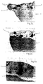
- Fig. 3 shows the section corresponding to Fig. 2 of an already used knife with a sufficiently hard coating
- 3a is the micrograph a section of FIG. 3
- Fig. 4 shows a section accordingly 2 of a used knife, in which the coating is none has sufficient hardness
- 4a shows a micrograph of the Section of Fig. 4
- Figure 4b is a detail from Figure 4a
- 5 shows a micrograph of a hard material coating according to the invention
- 6 shows a knife with a hard material coating according to the Invention.
- the chopping knife consists of a base body 1 made of base material and a hard material coating 2 which has the cutting edge 3. in the The area of the coating 2 is the base material of the base body 1 hardened. 3 shows the wear of the base material of the original contour 4 to the contour 5, which causes the coating 2 protrudes over the base body 1 by the distance 6.
- 3a shows the protrusion of the coating 2 over the base body 1 in a micrograph.
- At the forefront of the Coating 2 shows two carbides 7, which wear the Coating 2 resist and thus the entire coating 2 give a hardness that corresponds to that of the carbides.
- Fig. 4 shows the course of wear on the cutting edge 3 when the Wear resistance of the coating 2 is too low.
- FIGS. 5 and 6 are a high one Proportion of large, compact carbides 7 embedded in the matrix material 8.
- the basic material of the knife is designated 9.
- the hardness of the Coating 2 results from the large carbides lying on the edge 7. If these carbides 7 are worn or broken out, the surrounding matrix material 8 worn away until new Carbide grains 7 come to the surface, which the layer again Issue hardness that corresponds to the hardness of the carbide itself.
Landscapes
- Engineering & Computer Science (AREA)
- Mechanical Engineering (AREA)
- Coating By Spraying Or Casting (AREA)
- Knives (AREA)
- Other Surface Treatments For Metallic Materials (AREA)
- Polishing Bodies And Polishing Tools (AREA)
- Nonmetal Cutting Devices (AREA)
Abstract
Description
- bei Maismessern mindestens 0,1 bis höchstens 0, 2 mm,
- bei Gras-(und anderen Pflanzen zur Silage)messern mindestens 0,3 bis höchstens 0, 5 mm,
- bei Gegenschneiden in der Maisernte mindestens 0,6 bis höchstens 1,5 mm.
Claims (11)
- Hartstoffbeschichtung für Messer oder Schneiden mit in einem Matrixmaterial eingebetteten Hartstoffpartikeln, dadurch gekennzeichnet, daß diese Hartstoffpartikel (7) einen Durchmesser von 40 bis 100 µm aufweisen.
- Hartstoffbeschichtung nach Anspruch 1, dadurch gekennzeichnet, daß der Flächenanteil dieser Hartstoffpartikel (7) mit einem Durchmesser von 40 bis 100 µm im Schliffbild der Hartstoffbeschichtung (2) mindestens 30% beträgt.
- Hartstoffbeschichtung nach Anspruch 1 oder 2, dadurch gekennzeichnet, daß die Hartstoffpartikel (7) mit einem Durchmesser von 40 bis 100 µm im Matrixmaterial (8) gleichmäßig verteilt sind.
- Hartstoffbeschichtung nach einem der vorhergehenden Ansprüche, dadurch gekennzeichnet, daß die Härte der Hartstoffpartikel (7) größer als 1400 HV ist.
- Hartstoffbeschichtung nach einem der vorhergehenden Ansprüche, dadurch gekennzeichnet, daß die Hartstoffpartikel Karbide, Nitride oder Oxide, vorzugsweise Wolframkarbide, sind.
- Hartstoffbeschichtung nach einem der vorhergehenden Ansprüche, dadurch gekennzeichnet, daß das Matrixmaterial (8) eine Härte von 500 bis 800 HV hat.
- Hartstoffbeschichtung nach einem der vorhergehenden Ansprüche, dadurch gekennzeichnet, daß die Matrix (8) Nickel oder Kobalt oder Nickel-Chrom-Silizium-Verbindungen enthält.
- Hartstoffbeschichtung nach einem der vorhergehenden Ansprüche, dadurch gekennzeichnet, daß die erforderliche, optimale Dicke der Schicht vom zu schneidenden Material, vom Anteil und von der Härte der Hartstoffpartikel, der Matrixhärte und der abnutzbaren Beschichtungsbreite abhängt und bei Häckslern in der Feldfruchternte vorzugsweise beträgt:bei Maismessern mindestens 0,1 bis höchstens 0, 2 mm,bei Gras-(und anderen Pflanzen zur Silage)messern mindestens 0,3 bis höchstens 0, 5 mm,bei Gegenschneiden in der Maisernte mindestens 0,6 bis höchstens 1,5 mm.
- Messer bzw. Schneide mit einer Schneidkante, die mit einer Hartstoffbeschichtung aus in einem Matrixmaterial eingebetteten Hartstoffpartikeln versehen ist, dadurch gekennzeichnet, daß in dem Matrixmaterial (8) Hartstoffpartikel (7) mit einem Durchmesser von 40 bis 100 µm eingebettet sind.
- Messer bzw. Schneide nach Anspruch 9, dadurch gekennzeichnet, daß der Flächenanteil der vorzugsweise gleichmäßig im Matrixmaterial (8) verteilten Hartstoffpartikel (7) (mit einem Durchmesser von 40 bis 100 µm) im Schliffbild der Hartstoffbeschichtung (2) mindestens 30% ist, wobei die Hartstoffpartikel (7) vorzugsweise eine Härte von mindestens 1400 HV haben.
- Messer bzw. Schneide nach Anspruch 9 oder 10, dadurch gekennzeichnet, daß die Hartstoffpartikel Karbide, Nitride oder Oxide, vorzugsweise Wolframkarbide, sind.
Applications Claiming Priority (3)
| Application Number | Priority Date | Filing Date | Title |
|---|---|---|---|
| AT0073397A AT404471B (de) | 1997-04-28 | 1997-04-28 | Hartstoffbeschichtung für messer oder schneiden |
| AT73397 | 1997-04-28 | ||
| AT733/97 | 1997-04-28 |
Publications (3)
| Publication Number | Publication Date |
|---|---|
| EP0875323A2 true EP0875323A2 (de) | 1998-11-04 |
| EP0875323A3 EP0875323A3 (de) | 1998-11-25 |
| EP0875323B1 EP0875323B1 (de) | 2001-12-05 |
Family
ID=3498374
Family Applications (1)
| Application Number | Title | Priority Date | Filing Date |
|---|---|---|---|
| EP98105765A Expired - Lifetime EP0875323B1 (de) | 1997-04-28 | 1998-03-30 | Hartstoffbeschichtung für Messer oder Schneiden |
Country Status (4)
| Country | Link |
|---|---|
| US (1) | US6067784A (de) |
| EP (1) | EP0875323B1 (de) |
| AT (1) | AT404471B (de) |
| DE (1) | DE59802291D1 (de) |
Cited By (3)
| Publication number | Priority date | Publication date | Assignee | Title |
|---|---|---|---|---|
| CN102848412A (zh) * | 2011-05-24 | 2013-01-02 | 好使有限责任公司和两合公司 | 刀具和切割装置以及切割方法 |
| EP2319669A3 (de) * | 2009-11-05 | 2013-11-06 | Busatis GmbH | Messer zur tangentialen Entfernung einer Oberfläche eines Werkstücks |
| EP3984645A1 (de) * | 2020-09-21 | 2022-04-20 | Gebrüder Busatis Gesellschaft m.b.H. | Schneidelement |
Families Citing this family (22)
| Publication number | Priority date | Publication date | Assignee | Title |
|---|---|---|---|---|
| DE19836392A1 (de) * | 1998-08-12 | 2000-02-17 | Wolfgang Wiesener | Oberflächenbeschichtung, körnige Mischung zur Zufuhr zu einer Plasmabeschichtung und Oberflächenbeschichtungsverfahren |
| AT410156B (de) * | 2001-06-05 | 2003-02-25 | Busatis Gmbh | Schneidelement für eine pflückwalze zum ernten von stengeligem erntegut |
| DE10229736A1 (de) * | 2002-07-02 | 2004-01-15 | Claas Saulgau Gmbh | Mähscheiben für Scheibenmähwerke |
| US7632175B2 (en) * | 2004-05-04 | 2009-12-15 | Blount, Inc. | Cutting blade hard-facing method and apparatus |
| EP1796881A4 (de) * | 2004-08-30 | 2008-11-19 | Sundeo Technologies Llc | Schneidklinge |
| DE102004052682B4 (de) * | 2004-10-29 | 2013-02-28 | Fraunhofer-Gesellschaft zur Förderung der angewandten Forschung e.V. | Selbstschärfendes, schnitthaltiges Schneidwerkzeug für Mühlen |
| US7897265B2 (en) * | 2006-01-26 | 2011-03-01 | Hamilton Sundstrand Corporation | Low cost, environmentally favorable, chromium plate replacement coating for improved wear performance |
| US7955721B2 (en) * | 2008-01-16 | 2011-06-07 | Hamilton Sundstrand Corporation | Article having cobalt-phosphorous coating and method for heat treating |
| US8592711B2 (en) * | 2009-10-01 | 2013-11-26 | George H. Lambert | Apparatus and method of electronically impregnating a wear-resistant cutting edge |
| US9144196B2 (en) | 2009-10-14 | 2015-09-29 | Thomas J. FRANCIS | Lawn care maintenance apparatus |
| BE1019956A3 (nl) * | 2011-04-26 | 2013-03-05 | Cnh Belgium Nv | Hakmes met verhardende bekleding. |
| US9038359B2 (en) * | 2012-11-12 | 2015-05-26 | Deere & Company | Rotary implement having hard metallic layer and method therefor |
| CA2920175A1 (en) * | 2013-02-08 | 2013-05-01 | Thomas J. Francis | Lawn care maintenance apparatus |
| AT13482U1 (de) | 2013-04-04 | 2014-01-15 | Busatis Gmbh | Häckselmesser |
| EP3254813B1 (de) * | 2015-06-22 | 2021-04-07 | Kyocera Corporation | Schneidgerät |
| US20180029241A1 (en) * | 2016-07-29 | 2018-02-01 | Liquidmetal Coatings, Llc | Method of forming cutting tools with amorphous alloys on an edge thereof |
| US10321633B1 (en) * | 2016-11-10 | 2019-06-18 | Ronald J. Kile | Threshing bars with reinforced spikes and cutting blades |
| EP3560667B1 (de) * | 2016-12-26 | 2021-08-11 | Kyocera Corporation | Messer |
| US10994379B2 (en) | 2019-01-04 | 2021-05-04 | George H. Lambert | Laser deposition process for a self sharpening knife cutting edge |
| US11060176B2 (en) | 2019-10-24 | 2021-07-13 | Deere & Company | Cutting blade for an agricultural implement, and method of manufacturing the same |
| US11647698B2 (en) | 2020-10-07 | 2023-05-16 | Deere & Company | Chopper blade with hard face |
| CN113857778B (zh) * | 2021-09-16 | 2023-12-12 | 江苏富捷刀业有限公司 | 一种开垦刀的自动化流水线式加工工艺 |
Citations (3)
| Publication number | Priority date | Publication date | Assignee | Title |
|---|---|---|---|---|
| GB2176683A (en) * | 1985-06-21 | 1987-01-07 | George Lucas | Rotary lawn mower blade |
| US5096465A (en) * | 1989-12-13 | 1992-03-17 | Norton Company | Diamond metal composite cutter and method for making same |
| EP0628379A1 (de) * | 1993-06-11 | 1994-12-14 | Helmut Schäfer | Verfahren zur Herstellung von selbstschärfenden Messerschneiden sowie selbstschärfende Messerschneide |
Family Cites Families (11)
| Publication number | Priority date | Publication date | Assignee | Title |
|---|---|---|---|---|
| US3647401A (en) * | 1969-06-04 | 1972-03-07 | Du Pont | Anisodimensional tungsten carbide platelets bonded with cobalt |
| US3660050A (en) * | 1969-06-23 | 1972-05-02 | Du Pont | Heterogeneous cobalt-bonded tungsten carbide |
| US3989554A (en) * | 1973-06-18 | 1976-11-02 | Hughes Tool Company | Composite hardfacing of air hardening steel and particles of tungsten carbide |
| DE3216456A1 (de) * | 1982-05-03 | 1983-11-03 | Robert Bosch Gmbh, 7000 Stuttgart | Verfahren zum einbetten von hartstoffen in die oberflaeche von spanabhebenden werkzeugen |
| US4697320A (en) * | 1984-06-28 | 1987-10-06 | Hitachi, Ltd. | Roll for a rolling mill, method of producing the same and the rolling mill incorporating the roll |
| US4945640A (en) * | 1987-09-03 | 1990-08-07 | Diwakar Garg | Wear resistant coating for sharp-edged tools and the like |
| US4836307A (en) * | 1987-12-29 | 1989-06-06 | Smith International, Inc. | Hard facing for milled tooth rock bits |
| US5069872A (en) * | 1989-09-08 | 1991-12-03 | Penoza Frank J | Cutting tool |
| US5351588A (en) * | 1992-12-31 | 1994-10-04 | Penoza Frank J | Hand shear |
| DE4322544C1 (de) * | 1993-07-07 | 1995-03-02 | Fein C & E | Verfahren zum Sägen von duktilen Eisenwerkstoffen |
| GB2311085B (en) * | 1996-03-12 | 2000-03-08 | Smith International | Rock bit with hardfacing material incorporating spherical cast carbide particles |
-
1997
- 1997-04-28 AT AT0073397A patent/AT404471B/de not_active IP Right Cessation
-
1998
- 1998-03-30 DE DE59802291T patent/DE59802291D1/de not_active Expired - Lifetime
- 1998-03-30 EP EP98105765A patent/EP0875323B1/de not_active Expired - Lifetime
- 1998-04-28 US US09/067,892 patent/US6067784A/en not_active Expired - Lifetime
Patent Citations (3)
| Publication number | Priority date | Publication date | Assignee | Title |
|---|---|---|---|---|
| GB2176683A (en) * | 1985-06-21 | 1987-01-07 | George Lucas | Rotary lawn mower blade |
| US5096465A (en) * | 1989-12-13 | 1992-03-17 | Norton Company | Diamond metal composite cutter and method for making same |
| EP0628379A1 (de) * | 1993-06-11 | 1994-12-14 | Helmut Schäfer | Verfahren zur Herstellung von selbstschärfenden Messerschneiden sowie selbstschärfende Messerschneide |
Cited By (4)
| Publication number | Priority date | Publication date | Assignee | Title |
|---|---|---|---|---|
| EP2319669A3 (de) * | 2009-11-05 | 2013-11-06 | Busatis GmbH | Messer zur tangentialen Entfernung einer Oberfläche eines Werkstücks |
| CN102848412A (zh) * | 2011-05-24 | 2013-01-02 | 好使有限责任公司和两合公司 | 刀具和切割装置以及切割方法 |
| CN102848412B (zh) * | 2011-05-24 | 2016-05-04 | 好使有限责任公司和两合公司 | 刀具和切割装置以及切割方法 |
| EP3984645A1 (de) * | 2020-09-21 | 2022-04-20 | Gebrüder Busatis Gesellschaft m.b.H. | Schneidelement |
Also Published As
| Publication number | Publication date |
|---|---|
| ATA73397A (de) | 1998-04-15 |
| DE59802291D1 (de) | 2002-01-17 |
| EP0875323A3 (de) | 1998-11-25 |
| AT404471B (de) | 1998-11-25 |
| EP0875323B1 (de) | 2001-12-05 |
| US6067784A (en) | 2000-05-30 |
Similar Documents
| Publication | Publication Date | Title |
|---|---|---|
| EP0875323B1 (de) | Hartstoffbeschichtung für Messer oder Schneiden | |
| EP2842412B1 (de) | Erntegutbearbeitungs- und/oder Förderelement für einen Feldhäcksler | |
| EP2387873B1 (de) | Land- oder forstwirtschaftliches messer aus mehrschichtstahl | |
| DE202016105163U1 (de) | Häckselaggregat eines Feldhäckslers | |
| DE202006017540U1 (de) | Häckselmesser | |
| EP3401048B1 (de) | Sägeblatt für eine säge zum schneiden von stängeligem halmgut | |
| EP1935231A1 (de) | Häckselmesser für landwirtschaftliche Erntemaschinen | |
| DE102019116945A1 (de) | Gegenschneide | |
| EP3493937B1 (de) | Erntemesser und verfahren zu dessen herstellung | |
| EP3701781B1 (de) | Einsatz aus hartmetall für eine landwirtschaftliche vorrichtung | |
| EP1040746A1 (de) | Vorrichtung zum Pflücken von Fruchtständen | |
| DD260178A3 (de) | Schneidmesser fuer erntemaschinen | |
| EP3664593B1 (de) | Messerklinge für ein mähmesser einer landwirtschaftlichen erntemaschine | |
| DE3906026A1 (de) | Kreisrundes messer zum einbau in eine schneidvorrichtung zum zerteilen von rollen von auf huelsen gewickelter band- oder folienfoermiger ware | |
| EP3949715A1 (de) | Klinge für rotierende messer und maisgebiss | |
| DE3327895C2 (de) | Drehbare Mähscheibe | |
| AT405475B (de) | Schneidleiste | |
| EP0829198B1 (de) | Häckselvorrichtung | |
| DE3826984A1 (de) | Maehscheibe | |
| DE102008049317B4 (de) | Schneidmesser für einen Kreiselmäher, Kreiselmäher mit einem derartigen Schneidmesser sowie Verfahren zum Herstellen eines derartigen Schneidmessers | |
| CH620713A5 (de) | ||
| DE102021116404A1 (de) | Erntemaschine für Halm- und Blattgut mit einem Schneidwerk und wenigstens einem Zusatzmesser im Einzugskanal | |
| AT15150U1 (de) | Kombinierte Gegenschneide | |
| EP4356703A1 (de) | Hackschar | |
| DE102020125731A1 (de) | Frässtift |
Legal Events
| Date | Code | Title | Description |
|---|---|---|---|
| PUAI | Public reference made under article 153(3) epc to a published international application that has entered the european phase |
Free format text: ORIGINAL CODE: 0009012 |
|
| PUAL | Search report despatched |
Free format text: ORIGINAL CODE: 0009013 |
|
| AK | Designated contracting states |
Kind code of ref document: A2 Designated state(s): BE DE FR GB IE |
|
| AX | Request for extension of the european patent |
Free format text: AL;LT;LV;MK;RO;SI |
|
| AK | Designated contracting states |
Kind code of ref document: A3 Designated state(s): AT BE CH DE DK ES FI FR GB GR IE IT LI LU MC NL PT SE |
|
| AX | Request for extension of the european patent |
Free format text: AL;LT;LV;MK;RO;SI |
|
| 17P | Request for examination filed |
Effective date: 19990331 |
|
| AKX | Designation fees paid |
Free format text: BE DE FR GB IE |
|
| 17Q | First examination report despatched |
Effective date: 20000613 |
|
| GRAG | Despatch of communication of intention to grant |
Free format text: ORIGINAL CODE: EPIDOS AGRA |
|
| GRAG | Despatch of communication of intention to grant |
Free format text: ORIGINAL CODE: EPIDOS AGRA |
|
| GRAH | Despatch of communication of intention to grant a patent |
Free format text: ORIGINAL CODE: EPIDOS IGRA |
|
| GRAH | Despatch of communication of intention to grant a patent |
Free format text: ORIGINAL CODE: EPIDOS IGRA |
|
| GRAA | (expected) grant |
Free format text: ORIGINAL CODE: 0009210 |
|
| AK | Designated contracting states |
Kind code of ref document: B1 Designated state(s): BE DE FR GB IE |
|
| REG | Reference to a national code |
Ref country code: GB Ref legal event code: IF02 |
|
| REG | Reference to a national code |
Ref country code: IE Ref legal event code: FG4D Free format text: GERMAN |
|
| REF | Corresponds to: |
Ref document number: 59802291 Country of ref document: DE Date of ref document: 20020117 |
|
| GBT | Gb: translation of ep patent filed (gb section 77(6)(a)/1977) |
Effective date: 20020218 |
|
| PLBE | No opposition filed within time limit |
Free format text: ORIGINAL CODE: 0009261 |
|
| STAA | Information on the status of an ep patent application or granted ep patent |
Free format text: STATUS: NO OPPOSITION FILED WITHIN TIME LIMIT |
|
| 26N | No opposition filed | ||
| REG | Reference to a national code |
Ref country code: DE Ref legal event code: R082 Ref document number: 59802291 Country of ref document: DE Representative=s name: PUCHBERGER, BERGER & PARTNER, AT Ref country code: DE Ref legal event code: R082 Ref document number: 59802291 Country of ref document: DE Representative=s name: MEHLER ACHLER PATENTANWAELTE, DE |
|
| REG | Reference to a national code |
Ref country code: DE Ref legal event code: R082 Ref document number: 59802291 Country of ref document: DE Representative=s name: PUCHBERGER, BERGER & PARTNER, AT |
|
| REG | Reference to a national code |
Ref country code: GB Ref legal event code: 732E Free format text: REGISTERED BETWEEN 20140807 AND 20140813 |
|
| REG | Reference to a national code |
Ref country code: DE Ref legal event code: R082 Ref document number: 59802291 Country of ref document: DE Representative=s name: PUCHBERGER & PARTNER PATENTANWAELTE, AT Effective date: 20140813 Ref country code: DE Ref legal event code: R082 Ref document number: 59802291 Country of ref document: DE Representative=s name: PUCHBERGER & PARTNER PATENTANWAELTE, AT Effective date: 20120121 Ref country code: DE Ref legal event code: R082 Ref document number: 59802291 Country of ref document: DE Representative=s name: PUCHBERGER, BERGER & PARTNER, AT Effective date: 20140813 Ref country code: DE Ref legal event code: R082 Ref document number: 59802291 Country of ref document: DE Representative=s name: PUCHBERGER, BERGER & PARTNER, AT Effective date: 20120121 Ref country code: DE Ref legal event code: R081 Ref document number: 59802291 Country of ref document: DE Owner name: GEBRUEDER BUSATIS GESELLSCHAFT M.B.H., AT Free format text: FORMER OWNER: BUSATIS GMBH, PURGSTALL, AT Effective date: 20140813 |
|
| REG | Reference to a national code |
Ref country code: FR Ref legal event code: TP Owner name: GEBRUDER BUSATIS GESELLSCHAFT M.B.H., AT Effective date: 20140922 |
|
| REG | Reference to a national code |
Ref country code: FR Ref legal event code: PLFP Year of fee payment: 19 |
|
| REG | Reference to a national code |
Ref country code: FR Ref legal event code: PLFP Year of fee payment: 20 |
|
| PGFP | Annual fee paid to national office [announced via postgrant information from national office to epo] |
Ref country code: FR Payment date: 20170322 Year of fee payment: 20 Ref country code: DE Payment date: 20170315 Year of fee payment: 20 |
|
| PGFP | Annual fee paid to national office [announced via postgrant information from national office to epo] |
Ref country code: IE Payment date: 20170321 Year of fee payment: 20 Ref country code: BE Payment date: 20170321 Year of fee payment: 20 Ref country code: GB Payment date: 20170322 Year of fee payment: 20 |
|
| REG | Reference to a national code |
Ref country code: DE Ref legal event code: R071 Ref document number: 59802291 Country of ref document: DE |
|
| REG | Reference to a national code |
Ref country code: BE Ref legal event code: PD Free format text: DETAILS ASSIGNMENT: CHANGE OF OWNER(S), AFFECTATION / CESSION Effective date: 20140814 Ref country code: BE Ref legal event code: MK Effective date: 20180330 |
|
| REG | Reference to a national code |
Ref country code: GB Ref legal event code: PE20 Expiry date: 20180329 |
|
| PG25 | Lapsed in a contracting state [announced via postgrant information from national office to epo] |
Ref country code: GB Free format text: LAPSE BECAUSE OF EXPIRATION OF PROTECTION Effective date: 20180329 |
|
| REG | Reference to a national code |
Ref country code: IE Ref legal event code: MK9A |
|
| PG25 | Lapsed in a contracting state [announced via postgrant information from national office to epo] |
Ref country code: IE Free format text: LAPSE BECAUSE OF EXPIRATION OF PROTECTION Effective date: 20180330 |